■
■
■
■
□
□
□
□
/
■ □ NSC 98-2221-E-009-039-MY2 2009 8 1 2011 7 31 ( ) □ ■ 99 8 5Microstructural Characterization and Phase Formation Mechanisms at the Interface between Titanium and Ceria/Zirconia Ceramics at 1550°°°°C
Yao-Wen Chang and Chien-Cheng Lin
Department of Materials Science and Engineering, National Chiao Tung University, Hsinchu 30050, Taiwan
Abstract
Various CeO2/ZrO2 samples were fabricated by sintering, whereby CeO2 was completely dissolved or reacted with ZrO2 as a solid solution or Ce2Ze3O10 and Ce2Ze2O7 ternary compounds. Sintered samples were allowed to react with Ti at 1550°C for 4 h in argon. Microstructural characterization was conducted using x-ray diffraction and analytical electron microscopy. The CeO2/ZrO2 samples became more stable with increasing CeO2 because CeO2 was hardly reacted and dissolved in Ti. The incorporation of more than 50 mol% CeO2 could effectively suppress the interfacial reactions in the Ti side, where relatively a small amount of β'-Ti(Zr, O) was found. Moreover, the content of O in
α-Ti(O) far away from the interface was significantly decreasing with
increasing amounts of CeO2. Because CeO2 was hardly dissolved into Ti, it completely remained in the residual ZrO2, leading to the formation of spherical and worm-like Ce2Ze3O10 in the outermost 10 mol% CeO2 -ZrO2 sample. In the outermost 30-50 mol% CeO2 -ZrO2 samples, Ce2Ze2O7 was formed due to the outward diffusion of O and Zr away from Ce2Ze3O10 into Ti. CeO2 re-precipitated in the samples containing 50-70 mol% CeO2, because the solubility of CeO2 in Ti was
quite limited. On the ceramic side far from the original interface, spherical α-Zr and ZrO2-x were formed in the 10 mol% CeO2 -ZrO2 sample. Ce2Zr2O7 was formed in addition to residual ZrO2-x in the 30 mol% CeO2 -ZrO2 sample. Dense α-Zr grains existed along the grain boundaries of the Ce2Zr2O7 matrix in the 50 mol% CeO2 -ZrO2 sample. In the 70 mol% CeO2 -ZrO2 sample, free CeO2 existed in the Ce2Zr2O7 matrix. However, CeO was found in the sample containing 100 mol% CeO2.
I. Introduction
High specific strength and good corrosion resistance have led to the large-scale use of titanium in the aerospace and chemical processing industries. However, they are extremely reactive to ceramics at high temperatures, resulting in chemical reaction affected-surface. The interfacial reactions between titanium and ceramics play an important role in the titanium precision casting. The interstitial elements ( e.g., C, N, O, H) from the ceramic mold have a great tendency to enter into the titanium alloys during casting and cause the deterioration of mechanical properties.
Many researches1-5 have been working on the reactions of the titanium with various ceramic molds or crucibles in the last few decades. Weber et al.1 presented an unspecified feather-like eutectic phase in the reaction zone of Ti and MgO-ZrO2 crucible. Ruh
2
found that zirconium entered the titanium lattice substitutionally and oxygen went to interstitial positions during the reactions between zirconia and titanium at elevated temperatures. While previous studies had been focused on the reactions taking place in the metal side, the transformation in the ceramic side had not been well attended. Thus,
the role of the ceramic mold in the interfacial reactions has not been fully understood to date.
Recently, Lin and his colleagues6-12 have thoroughly investigated the phase formation mechanisms and microstructural evolution at the interface between titanium (or titanium alloys) and 3Y-ZrO2 (or various ratios of Y2O3/ZrO2) using analytical electron microscopy. The
α-Ti(O), β'-Ti(Zr, O) and/or Ti2ZrO were formed near the original interface due to the dissolution of ZrO2 into Ti. Both lamellar orthorhombic Ti2ZrO and spherical hexagonal Ti2ZrO were found in
α-Ti(Zr, O) after reaction at 1550oC.8 Lin and Lin9 also found the intergranular α-Zr, twinned t'-ZrO2-x, lenticular t-ZrO2-x, and/or ordered
c-ZrO2-x in the zirconia side far from the interface between Ti and 3Y-ZrO2 after reaction at 1550
o
C. Concerning the reaction of Ti melt with various Y2O3/ZrO2 samples at 1700°C,12 the incorporation of more than 30 vol% Y2O3 in ZrO2 could effectively suppress the reactions in the Ti side where only a very small amount of α-Ti and β'-Ti was found. Y2O3 re-precipitated in the samples containing 30-70 vol% Y2O3, because the solubility of Y2O3 in Ti was very low.
Several recent publications13-15 have reported the importance of ceramic materials based on solid solutions of the ZrO2–CeO2 system, mainly those formulated in the ZrO2–rich region. There are many potential applications of these materials, such as a toughened ceramic material in view of the existence of a relatively wide field of the tetragonal zirconia solid solution in the system ZrO2–CeO2. It is well known that ceria-doped zirconia polycrystals (Ce-TZP) exhibit high transformation toughness, even when compared to Y-TZP ceramics.13-17 However, CeO2 was cheaper than Y2O3. The ceria partially stabilized zirconia
has been considered as one of the most important industry ceramic material because of its good fracture toughness.
At present study, various ratios of CeO2/ZrO2 samples were attempted to achieve better control over the reactions on the titanium side as well as the ceramic side. The powder mixtures of CeO2/ZrO2 were sintered and then allowed to react with titanium at 1550°C for 4 h in argon. Various reaction layers at the interface between titanium and CeO2/ZrO2 samples were characterized using analytical scanning electron microscopy and analytical transmission electron microscopy. Finally, we would attempt to elucidate the effect of CeO2 on the interfacial reactions between Ti and CeO2/ZrO2 samples.
II. Experimental Procedures
Starting powders used were zirconia (> 99.95 wt% ZrO2+HfO2 with HfO2 accounting for approximately 2%-3% of this total, < 0.02 wt% Fe2O3, < 0.02 wt% TiO2, < 0.004 wt% SiO2, < 0.004 wt% Al2O3, < 0.002 wt% CaO; 0.5 µm in average; Toyo Soda Mfg. Co., Ltd. Tokyo, Japan), cercia (> 99.9 wt% CeO2, < 0.04 wt% CaO, < 0.03 wt% SiO2, < 0.02 wt% Fe2O3, < 0.01 wt% Na2O3; 0.5 µm in average; NYC, Ltd., Fukuoka, Japan).
The CeO2/ZrO2 samples contained 10, 30, 50, 70, and 100 mol% CeO2, respectively, and were balanced with ZrO2. The sample consisting of 10 mol% CeO2 and 90 mol% ZrO2 was designated as 10Ce90Zr, and so on. Powder mixtures were dispersed in ethanol. The pH of the suspension was adjusted to 11 by adding NH4OH. The suspension was ultrasonically vibrated for 10 minutes (Model XL-2020, Sonicator, Heat Systems Inc., Farmingdale, NY), dried in an oven at 150°C, ground with
an agate mortar and pestle, and then screened through 80 mesh. The powder mixtures of CeO2 and ZrO2 were pressed into disks (20 mm in diameter x 5 mm thick) at a pressure of 200MPa and then sintered in air at 1400°C for 4 h at 5°C/min heating rate (Lindberg/Blue M STF54454C, Thermo Fisher Scientific Inc., Waltham Massachusetts, USA). Thereafter, the furnace cooled down to room temperature.
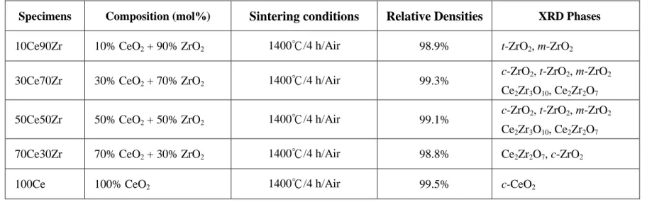
The apparent densities of CeO2/ZrO2 powder mixtures were measured using a gas pycnometer (Model MultiVolume Pycnometer 1305, Micromeritics, Norcross, GA) with 99.99% pure helium. The bulk densities of sintered samples were determined using the Archimedes method. The relative densities of the sintered samples were calculated as follows: Relative density = (bulk density/true density) × 100%. For a non-porous powder, the apparent density approximates the true density and can be used as the reference point in calculating the relative density. The designations, compositions, sintering conditions, and relative densities of CeO2/ZrO2 samples are listed in Table I.
Commercially pure titanium plates (99.7% purity, Alfa Aesar, Ward Hill, MA) were brought to react with various sintered CeO2/ZrO2 samples at 1550°C for 4 h in argon. Firstly, bulk CeO2/ZrO2 samples and titanium plates were cut and machined to dimensions of 10 × 10 × 4 mm. Their surfaces were ground and polished with a diamond paste, and then ultrasonically cleaned in acetone. One titanium disc was inserted in between two pieces of each CeO2/ZrO2 sample to produce a sandwiched type, and then put in the graphite furnace mentioned above, which was preparatorily pressed under 5 MPa, evacuated to 2 x 10⁻⁴ Torr, and filled with argon to one atmospheric pressure. This cycle of evacuation and purging was repeated at least three times. The temperature was raised
to 1000°C at a heating rate of 30°C/min, to 1550°C at 25°C/min, and then held at 1550°C for 4 h. Thereafter, the temperature was lowed to 1000°C at a cooling rate of 25°C/min, and then the furnace cooled down to room temperature.
The phase identification of the sintered CeO2/ZrO2 samples was performed using an x-ray diffractometer (XRD, Model MXP18, Mac Science, Yokohama, Japan). The operating conditions of x-ray diffraction were Cu Kα radition at 50 kV and 150 mA, and a scanning
rate of 2 degrees/min.
A scanning electron microscope (SEM, Model JSM 6500F, JEOL Ltd., Tokyo, Japan) equipped with an energy dispersive x-ray spectrometer (EDS, Model ISIS 300, Oxford Instrument Inc., London, UK) was used for the microstructural observation on the interfaces between Ti and various CeO2/ZrO2 samples. Cross-sectional SEM specimens were cut and ground using standard procedures and finally polished using diamond pastes of 6, 3, and 1 µm in sequence.
The cross-sectional TEM specimens of the interfaces between Ti and various CeO2/ZrO2 samples were prepared by two different methods. Firstly, they were cut perpendicular to the interface and then polished, dimpled, and subsequently ion-beam-thinned using a precision ion-polishing system (PIPS, Model 691, Gatan, San Francisco, CA). The details of this traditional technique for preparing cross-sectional TEM specimens were described in a previous study.12 Secondly, the TEM samples were acquired by an innovative technique. A specific location on a metallographic sample was ion-bombarded using a focused ion beam (FIB, Model Nova 200, FEI Co., Hillsboro, OR). The FIB
operating parameters were adjusted so that the electron beam was 5 kV from 98 pA to 1.6 nA and the ion beam was 30 kV from 10 pA to 7 nA. A TEM specimen with a thickness less than 100 nm was electron-transparent. The final TEM specimen was approximately 12 x 5 x 0.05 µm in size.
The interfacial microstructures were then characterized using a transmission electron microscope (TEM, Model JEM 2100, JEOL Ltd., Tokyo, Japan) equipped with an energy dispersive x-ray spectrometer (EDS, Model ISIS 300, Oxford Instrument Inc., London, UK). Analyses of atomic configurations in various phases were performed using computer simulation software for crystallography (CaRIne Crystallography 3.1, Divergent S.A., France). Chemical quantitative analyses for various phases were conducted by the Cliff-Lorimer standardless technique.18 A conventional ZAF correction was operated using the LINK ISIS software.
III. Results and Discussion (1) XRD analyses
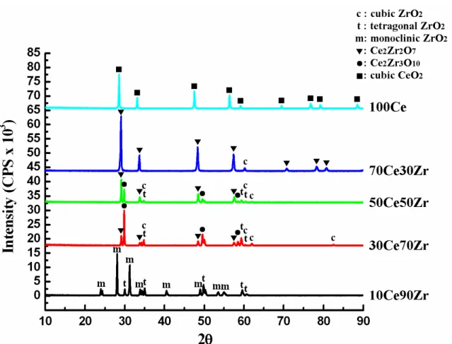
Figure 1 shows the x-ray diffraction spectra of various CeO2/ZrO2 samples as well as pure CeO2 after sintering. These spectra were arranged for CeO2, 70Ce30Zr, 50Ce50Zr, 30Ce70Zr, and 10Ce90Zr, respectively, in a sequence from top to bottom. X-ray phases of these sintered CeO2/ZrO2 samples are summarized in Table I. In the 10Ce90Zr, all of the CeO2 went into solid solution in zirconia such that only t-ZrO2 and m-ZrO2 were detected. Both of the 30Ce70Zr and 50Ce50Zr, c-ZrO2, t-ZrO2, tetragonal Ce2Zr3O10,
19-21
and cubic Ce2Ze2O7
22,23
were found. As for the 70Ce30Zr, Ce2Ze2O7 and only cubic ZrO2 phase were detected. In other words, the cubic ZrO2 was
fully stabilized in 70Ce30Zr. While the content of CeO2 was increasing from 30Ce70Zr to 50Ce50Zr, the amount of Ce2Ze2O7 was significantly gradually increasing and the decreasing content of Ce2Zr3O10. In the 100Ce, only cubic CeO2 was detected. In general, CeO2 was mutually dissolved or reacted with ZrO2 as a solid solution or Ce2Zr3O10 and Ce2Ze2O7 compounds in various sintered CeO2/ZrO2 samples. The Ce2Ze2O7 was formed due to the reduction of Ce
+4 ions to Ce+3 in ZrO2 with low oxygen partial pressure and Ce2O3 reacted with ZrO2 as a 1:2 Ce2O3•ZrO2 ternary compound.
Negas et al.24 pointed out that partial reduction of Ce4+ to Ce3+ can occur above 1400°C in air. The amount of Ce3+, however, seemed to be small below 1600°C, so that the ternary system ZrO2–CeO2–Ce2O3 could be regarded as the pseudobinary system ZrO2–CeO2 below 1600°C in air. The influence of oxygen partial pressure on the phase relation of solid solutions in Ce-Zr-O system is that the Ce+4 in a solid solution of ZrO2 will be reduced to Ce
+3
at increased temperature in reducing atmospheres (such as H2, CO, and NH4) or under a vacuum of 10-4 to 10-5 torr, or in an inert atmosphere (such as Ar and He) or in the atmosphere of flame furnaces with low oxygen partial pressure (for example, oxygen partial pressure 10-2 torr at 1400°C).23,25 Cerium is the second element of the rare earth series with an electronic configuration which can be described, taking into account that of Xenon, as (Xe) 6s25d14f1. In such a configuration, the volume of 6s and 5d orbital are greater than that of the 4f orbital. Therefore, the three 6s2 and 5d1 electron are the only ones participating for chemical bonds. For this reason, the valance of the lanthanide elements in their configurations is habitually 3+.
(2) Microstructures of Ti and various sintered CeO2/ZrO2 samples
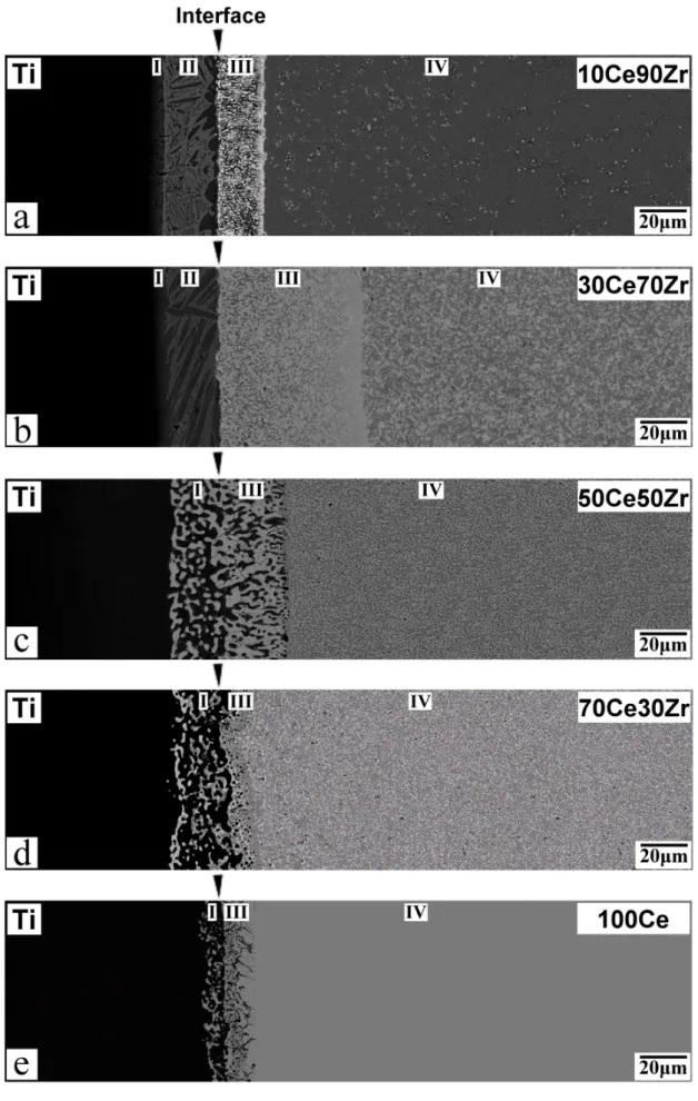
Figures 2(a)-(e) display the backscattered electron images of the cross-sections normal to the interfaces of Ti and various CeO2/ZrO2 samples after reaction at 1550°C for 4 h. Titanium is shown to the left of the micrograph, while zirconia is on the right-hand side. The vertical arrows in the upper side of individual figures indicate the original interfaces of Ti and individual CeO2/ZrO2 samples, respectively. The original interfaces were deliberately located according to the characteristic Kα x-ray maps of cerium (not shown), which was
relatively immobile compared with respect to Zr, O, and Ti, etc. To the left of the reaction layer “I” was the α-Ti with oxygen in solid solution. Based on EDS results, the content of oxygen in α-Ti(O) was apparently decreasing with increasing amount of CeO2. The composition of
α-Ti(O) in 10Ce90Zr was measured as 70.47 at% Ti and 29.53 at% O.
An α-Ti(O) in 70Ce30Zr was consisted of 85.72 at% Ti and 14.28 at% O.
Figure 2(a) and (b) indicated that extensive reactions took place at the interface between Ti and ZrO2 containing 10 mol% and 30 mol% CeO2. It was previously reported that needle-like α-Ti and some lamellar phases were usually found in the titanium side because of the interfacial reactions between Ti and ZrO2.
7,8,10,11
However, only a limited reaction took place on the titanium side at the interface between Ti and those samples containing more than 50 mol% CeO2, while pure CeO2 reacted minimally with Ti after reaction at 1550°C for 4 h. This indicated that interfacial reactions were effectively suppressed in those samples containing more than 50 mol% CeO2. This fact plays an important role in the engineering respect of Ti castings such that a controlled interfacial reaction results in a lower amount of α-casing and thus better
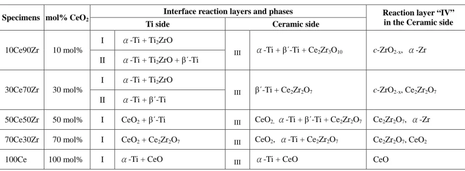
mechanical properties. Even though the system became more stable with increasing CeO2, several reaction layers were found on the zirconia side after the interfacial reactions between Ti and various CeO2/ZrO2 samples. Microstructures of the reaction layers at the interface between Ti and various CeO2/ZrO2 samples were characterized using SEM/EDS and TEM/EDS and the results are listed in Table II. The details will be described below.
(A) Reaction layer “II” on the metal side at the Ti/10Ce90Zr and Ti/30Ce70Zr interfaces
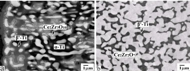
Figure 3(a) shows the backscattered electron image (BEI) of the reaction layer “II” at the Ti/10Ce90Zr interface after reaction at 1550°C for 4 h. The reaction layer “II” consisted of the acicular α-Ti (dark) in β'-Ti (bright) matrix and the lamellar Ti2ZrO (bright) precipitated in the α-Ti. The morphology of α-Ti abutted the original interface was very different from the corresponding reaction layer previously found 8,10-12 It inferred that the cause by the agglomeration of a large amount of oxygen in this region to the nearest left of the original interface. At high temperature, α-Ti dissolved a large amount of O and relatively a small amount of Zr, forming a metastable supersaturated solid solution α-Ti(O, Zr), thus resulting in the precipitation of the lamellar Ti2ZrO during cooling. Lin and Lin8 reported that the Ti2ZrO lamellae were precipitated from plate-like α-Ti by a eutectoid reaction during cooling. As more zirconia was dissolved in α-Ti, the β-Ti was formed and some of them was transformed into orthorhombic β'-Ti solid solution during cooling. Figure 3(b) shows the BEI of the reaction layer “II” at the Ti/30Ce70Zr interface after reaction at 1550°C for 4 h. The reaction layer “II” consisted of β'-Ti (bright) and α-Ti (dark). In this case, no Ti2ZrO was found in α-Ti (dark). It was believed that the α-Ti
dissolved a relatively small amount of zirconium due to much slower diffusion rate of zirconium than oxygen, thus no Ti2ZrO precipitated in
α-Ti during cooling.
(B) Reaction layer “III” on the ceramic side at the Ti/10Ce90Zr and Ti/30Ce70Zr interfaces
For the benefit of good resolution of TEM, figure 4(a) shows the TEM micrograph (bright-field image, BFI) of reaction layer “III”. The reaction layer “III” was consisting of α-Ti, β'-Ti, and Ce2Zr3O10 at the Ti/10Ce90Zr interface after reaction at 1550°C for 4 h. Arrow below the BFI indicates the original interface between reaction layers “II” and “III”. A large amount of spherical or worm-like Ce2Zr3O10 phase existed in the reaction layer “III”. Fig. 4(a) also shows Ti2ZrO lamellae precipitated in the α-Ti matrix. With the diffraction spots being indexed in Fig. 4(b), the orientation relationships of Ti2ZrO and
α-Ti were thus recognized as follows: [110]Ti2ZrO // [0001]α-Ti and
(110)Ti2ZrO // (10 1 0)α-Ti. The crystal structures of Ti2ZrO and α-Ti
were identified to be orthorhombic and hexagonal based upon the superimposed selected area diffraction patterns (SADPs), as shown in fig. 4(b). Figure 4(c) shows the SADP of Ce2Zr3O10 phase along the
zone axis of [001]. The crystal structure of Ce2Zr3O10 was identified to
be tetragonal from the SADP.
Figure 5(a) shows the BEI of the reaction layer “III” at the Ti/10Ce90Zr interface after reaction at 1550°C for 4 h. As 10Ce90Zr reacted with Ti at 1550°C for 4 h, an increasing amount of O and Zr from the
supersaturated 10 mol% CeO2-ZrO2 solid solution were gradually
dissolved in titanium. Because CeO2 remained in the solid solution
of CeO2 to ZrO2 gave rise to the formation of 2:3 CeO2•ZrO2 ternary compound (or Ce2Zr3O10). Based on EDS results, Ce2Zr3O10 consisted of 13.11 at% Ce, 20.52 at% Zr, and 66.37 at% O. The formation mechanisms of α-Ti, β'-Ti, and Ce2Zr3O10 in the case of Ti/10Ce90Zr in the reaction layer “III” can be expressed as follows:
0.1 CeO2 + 0.9 ZrO2 → (Ce0.1Zr0.9)O2 during sintering (1)
x-Ti + (Ce0.1Zr0.9)O2 → (x-Ti + 0.75 Zr + 1.5 O) + Ce0.1Zr0.15O0.5
→α-Ti (O, Zr)+ β'-Ti(Zr, O) + 0.05
Ce2Zr3O10 (2)
Figure 5(b) shows the BEI of the reaction layer “III” at the Ti/30Ce70Zr interface after reaction at 1550°C for 4 h. The reaction layer “III” consisted of β'-Ti (dark) and Ce2Zr2O7 (bright). Ce2Zr2O7 phase was dense and interconnected at the Ti/30Ce70Zr interface. The quantitative analyses of Ce2Zr2O7 by the EDS showed that it contained 18.21 at% Ce, 18.52 at% Zr, and 63.27 at% O. This reaction mechanism can be expressed as the following equation.
x-Ti + Ce2Zr3O10 → (y-Ti + Zr + 3 O) + Ce2Zr2O7
→β'-Ti(Zr, O) + Ce2Zr2O7 (3)
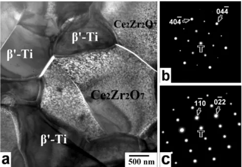
Figure 6(a) shows the BFI of reaction layer “III” at the Ti/30Ce70Zr interface after reaction at 1550°C for 4 h. The crystal structures of Ce2Zr2O7 and β'-Ti were identified to be cubic and orthorhombic from the SADPs as shown in Fig. 6(b) and (c) along the zone axes of [111], respectively. The Ce2Zr2O7 has possesses the pyochlore type structure
(space group Fd3m) in which one out of every eight oxygen ions is missing in the stoichiometric fluorite. The ideal Ce2Zr2O7 structure is described as an ordered cubic close-packed array of cations (16c and 16d sites) with the oxygen ions occupying seven-eighths of the tetrahedral sites (48f and 8a sites) between the cations. The oxygen vacancies in the remaining one-eighths of the tetrahedral sites (8b site) are also ordered.
(C) Reaction layers “I” and “III” at the Ti/50Ce50Zr and Ti/70Ce30Zr interfaces
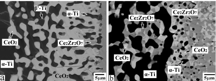
Figure 7(a) displays the BEI of reaction layers “I” and “III” at the Ti/50Ce50Zr interface after reaction at 1550°C for 4 h. Reaction layer “I” in 50Ce50Zr consisted of α-Ti, β'-Ti, and CeO2. For comparison, as shown in Fig. 7(a) together with Fig. 2, only very few β'-Ti was found in the reaction layer “I”. However, a relatively large amount of β'-Ti and α-Ti existed at the interface between Ti and ZrO2 containing 10-30 mol% CeO2. The reaction layer “III” in 50Ce50Zr consisted of α-Ti,
β'-Ti, CeO2, and Ce2Zr2O7. As 50Ce50Zr reacted with Ti, a large amount of O and Zr from ZrO2 were dissolved in titanium, giving rise to the formation of CeO2 due to the very limited solubility of CeO2 in Ti. From the EDS analyses, the CeO2 in the reaction layer “III” contained 32.14 at% Ce, 64.57 at% O, and 3.29 at% Zr. The re-precipitation of CeO2 in reaction layer “III” was dense and interconnected. It was concluded that increasing CeO2 content was useful for better controlling the interfacial reactions. The formation mechanisms of α-Ti, β'-Ti, CeO2, and Ce2Zr2O7 in the case of Ti/50Ce50Zr in the reaction layer “III” can be expressed as follows:
x-Ti + (Ce0.5Zr0.5)O2→ (x-Ti + 0.5 Zr + 1 O) + 0.5 CeO2
→β'-Ti(Zr, O) + α-Ti (Zr, O) + 0.5 CeO2 (5)
y-Ti + Ce2Zr3O10 → (y-Ti + Zr + 3 O) + Ce2Zr2O7
→β'-Ti(Zr, O) + Ce2Zr2O7 (6)
Figure 7(b) displays the BEI of reaction layers “I” and “III” at the Ti/70Ce30Zr interface after reaction at 1550°C for 4 h. Reaction layer “I” in 70Ce30Zr consisted of α-Ti, CeO2, and Ce2Zr2O7. For comparison, as shown in Fig. 7(b) together with Fig. 2, no β'-Ti were found in the reaction layer “I”. The reaction layer “III” in 70Ce30Zr consisted of CeO2, Ce2Zr2O7, and few α-Ti. The α-Ti phase was spherical and isolated at the Ti/70Ce30Zr interface. The formation mechanisms of α-Ti and CeO2 in the case of Ti/70Ce30Zr in the reaction layer “III” can be expressed as follows:
0.7 CeO2 + 0.3 ZrO2 →(Ce0.7Zr0.3)O2 durng sintering (7)
x-Ti + (Ce0.7Zr0.3)O2→ (x-Ti + 0.3 Zr + 0.6 O) + 0.7 CeO2
→α-Ti (Zr, O) + 0.7 CeO2 (8)
(D) Reaction layer “IV” on the ceramic side
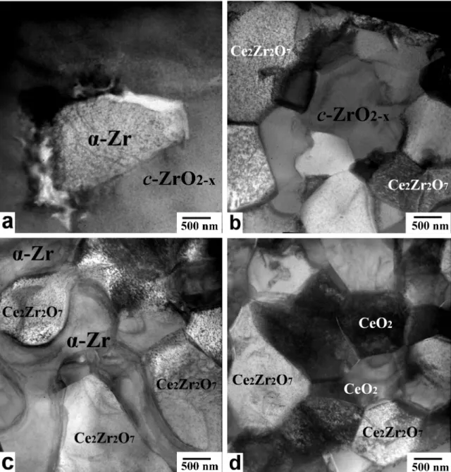
Figures 8(a)-(d) show the BFIs of reaction layer “IV” on the ceramic side far from the original interfaces of Ti and 10Ce90Zr, 30Ce70Zr, 50Ce50Zr,
and 70Ce30Zr, respectively, after reaction at 1550°C for 4 h. Figure 8(a) shows the α-Zr particle was embedded in c-ZrO2-x in reaction layer “IV” of 10Ce90Zr. It was believed that the oxidation-reduction reaction rather than dissolution was the predominant reaction mechanism in reaction layer “IV”. The dissolution did not play a significant role, as the titanium was not detected by EDS in reaction layer “IV”. It was obivous that the ZrO2-x was metastable because of the extraction of oxygen from ZrO2 by Ti. The α-Zr with oxygen in solid solution was excluded from metastable ZrO2-x. However a significant increase in oxygen vacancies, as a consequence of the reaction between Ti and 30Ce70Zr, triggered the stabilization effect of zirconia. Therefore, it was inferred that the zirconia could be in the cubic phase. Figure 8(b) shows several Ce2Zr2O7 grains were existed along the grain boundaries of
c-ZrO2-x in reaction layer “IV” of 30Ce70Zr. No α-Zr was found in the reaction layer “IV” of 30Ce70Zr. Cubic Ce2Zr2O7 was formed due to the decomposition of the Ce2Zr3O10. Since CeO2 was completely retained in ZrO2, no free CeO2 was found in 10Ce90Zr and 30Ce70Zr.
Figure 8(c) shows the BFI of Ce2Zr2O7 and dense α-Zr grain in the reaction layer “IV” of Ti/50Ce50Zr. The morphology of α-Zr in the reaction layer “IV” of Ti/50Ce50Zr was very different from 10Ce90Zr. Formation mechanisms of Ce2Zr2O7 and α-Zr in the case of Ti/50Ce50Zr in the reaction layer “IV” can be expressed in terms of the following equation:
Ce2Zr3O10 Ce2Zr2O7 + α-Zr (with O in solid solution) + 3O (pariially dissolved in β'-Ti) (9)
reaction at 1550°C for 4 h. Free CeO2 existed in reaction layers “IV”. The composition of CeO2 indicated that it contained 32.12 at% Ce, 64.99 at% O, and 2.89 at% Zr.
(3) A General Discriptions of Interfacial Reaction Layers
According to the previous discussion, the reaction layers were formed at the interface between titanium and various ceria/zirconia samples after reaction at 1550°C for 4 h (summarized in Table II). Briefly speaking, extensive reactions occurred at the interface between Ti and ZrO2 containing 10-30 mol% CeO2. However, interfacial reactions were effectively suppressed by incorporating more than 50 mol% CeO2. On the metal side near the original interface, β'-Ti and Ti2ZrO precipitated in the α-Ti matrix after Ti reacted with 10Ce90Zr, although β'-Ti and
α-Ti were found for the case of 30Ce70Zr. Furthermore, only a small
amount of β'-Ti was found for the case of 50Ce50Zr. No β'-Ti was found for the case of 70Ce30Zr and pure CeO2. In the outermost ceramic region, β'-Ti and α-Ti were found along with Ce2Zr3O10 in 10Ce90Zr, while β'-Ti and Ce2Zr2O7 were found in 30Ce70Zr. Free CeO2 existed in 50Ce50Zr and 70Ce30Zr due to a very limited solubility of CeO2 in Ti when ZrO2 was completely dissolved in Ti. On the ceramic side far from the original interface, spherical α-Zr was formed in addition to residual ZrO2-x in 10Ce90Zr, where α-Zr was excluded from metastable ZrO2-x. However, Ce2Zr2O7 was formed in addition to residual ZrO2-x in 30Ce70Zr. Dense α-Zr grains existed along the grain boundaries of Ce2Zr2O7 in 50Ce50Zr. Free CeO2 existed in Ce2Zr2O7 matrix in 70Ce30Zr. However, CeO was found in 100Ce. CeO2 was dissolved into ZrO2 as a solid solution or reacted with ZrO2 as Ce2Ze3O10 and Ce2Ze2O7 compound during sintering. Ce2Ze2O7 was formed due to the reduction of Ce
+4
with low oxygen partial pressure and Ce2O3 reacted with ZrO2 as a 1:2 Ce2O3• ZrO2 ternary compound (or Ce2Zr2O7). As 50Ce50Zr and 70Ce30Zr were reacted with Ti at 1550ºC for 4 h, CeO2 was re-precipitated due to the strong affinity of O and Zr to Ti and the very limited solubility of CeO2. CeO was found in the sample containing 100 mol% CeO2 due to the oxidation-reduction between Ti and CeO2. It was also noted that Ce2Ze2O7 was stable and retained in the sample after reaction at 1550ºC for 4 h.
IV. Conclusions
1. The incorporation of more than 50 mol% CeO2 significantly suppressed the interfacial reactions at the interfaces between Ti and various sintered CeO2/ZrO2 samples.
2. On the metal side near the original interface, a relatively large amount of β'-Ti and α-Ti were observed after Ti reacted with 10Ce90Zr or 30Ce70Zr at 1550ºC for 4 h. However, few β'-Ti was found after Ti reacted with 50Ce50Zr. No β'-Ti was found after Ti reacted with 70Ce30Zr or CeO2 at 1550ºC for 4 h.
3. After reaction at 1550ºC for 4 h, β'-Ti, α-Ti and Ce2Zr3O10 were found in the outermost region of 10Ce90Zr, while β'-Ti and Ce2Zr2O7 existed in the outermost region of 30Ce70Zr. The formation of Ce2Zr3O10 was caused by the extensive dissolution of ZrO2 in Ti together with a very limited solubility of CeO2. The formation of Ce2Zr2O7 was caused by the outward diffusion of O and Zr from Ce2Zr3O10 in Ti.
and 70Ce30Zr after reaction at 1550ºC for 4 h. This was due to the strong Ti affinity of O and Zr.
5. It was also noted that Ce2Ze2O7 was stable and retained in the sample containing more than 30 mol% CeO2 after reaction at 1550ºC for 4 h.
References
1
B. C. Weber, W. M. Thompson, H. O. Bielstein, and M. A. Schwartz, "Ceramic Crucible for Melting Titanium," J. Am. Ceram. Soc., 40 [11] 363-73 (1957).
2
R. Ruh, "Reaction of Zirconia and Titanium at Elevated Temperatures," J. Am. Ceram. Soc., 46 [7] 301-06 (1963).
3
R. L. Saha, T. K. Nandy, R. D. K. Misra, and K. T. Jacob, "Evaluation of the Reactive of Titanium with Mould Materials during Casting," Bull. Mater. Sci., 12 [5] 481-93 (1989).
4
R. L. Saha and R. D. K. Misra, "Formation of low-melting eutectic at the metal-mould interface during titanium casting in zircon sand moulds," J. Mater. Sci. Lett, 101318-19 (1991).
5
K. I. Suzuki, S. Watakabe, and K. Nishikawa, "Stability of Refractory Oxides for Mold Material of Ti-6Al-4V Alloy Precision Casting," J. Jpn. Inst. Met.,
60 [8] 734-43 (1996).
6
K. F. Lin and C. C. Lin, "Interfacial Reactions between Ti-6Al-4V Alloy and Zirconia Mold During Casting," J. Mater. Sci., 34 5899-906 (1999).
7
K. F. Lin and C. C. Lin, "Transmission Electron Microscope Investigation of the Interface between Titanium and Zirconia," J. Am. Ceram. Soc., 82 [11] 3179-85 (1999).
8
Zirconia Interface after Reaction at 1550oC," J. Am. Ceram. Soc., 88 [5] 1268-72 (2005).
9
K. L. Lin and C. C. Lin, "Zirconia-Related Phases in the Zirconia/Titanium Diffusion Couple after Annealing at 1100o to 1550oC," J. Am. Ceram. Soc., 88 [10] 2928-34 (2005).
10
K. L. Lin and C. C. Lin, "Microstructural Evolution and Formation Mechanism of the Interface Between Titanium and Zirconia Annealed at 1550oC," J. Am. Ceram. Soc., 89 [4] 1400-8 (2006).
11
K. L. Lin and C. C. Lin, "Effects of Annealing Temperature on Microstructural Development at the Interface Between Zirconia and Titanium," J. Am. Ceram. Soc., 90 [3] 893-9 (2007).
12
C. C. Lin, Y. W. Chang, and K. L. Lin, "Effect of Yttria on Interfacial Reactions Between Titanium Melt and Hot-Pressed Yttria/Zirconia Composites at 1700oC," J. Am. Ceram. Soc, 91 [7] 2321-27 (2008).
13
K. Tsukuma and M. Shimada, "Strength, Fracture Toughness and Vickers Hardness of CeO2-Stabilized Tetragonal ZrO2 Polycrystals (Ce-TZP)," J. Mater. Sci., 20 [4] 1178-84 (1985).
14
K. Tsukuma, "Mechanical Properties and Thermal Stability of CeO2
Containing Tetragonal Zirconia Polycrystals," Am. Ceram. Soc. Bull, 65 [10] 1386-89 (1986).
15
J. G. Duh, H. T. Dai, and B. S. Chiou, "Sintering Microstructure, Hardness, and Fracture Toughness Behaviour of Y2O3-CeO2-ZrO2," J. Am. Ceram. Soc, 71 [10]
813-19 (1988).
16
S. B. Bhaduri, A. Chakraborty, and R. M. Rao, "Method of Fabrication Ceria-Stabilized Tetragonal Zirconia Polycrystals," J. Am. Ceram. Soc, 71 [9] C-410-C-11 (1988).
17
J. Wang, X. H. Zheng, and R. Stevens, "Fabrication and Microstructure-Mechanical Property Relationships in Ce-TZPs," J. Mater. Sci., 27
[19] 5348-56 (1992).
18
G. Cliff and G. W. Lorimer, "The Quantitative Analysis of Thin Specimens,"
J. Microsc., 130 [3] 203-07 (1975).
19
S. Roitti and V. Longo, "Investigation of Phase Equilibrium Diagrams Among Oxides by means of Electrical Conductivity Measurements. Application of the Method to the System CeO2-ZrO2," Ceramurgia Int., 2 [2] 97-102 (1972).
20
V. Longo and D. Minichelli, "X-Ray Characterization of Ce2Zr3O10," J. Am.
Ceram. Soc, 56 [11] 600 (1973).
21
E. Tani, M. Yoshimura, and S. Somiya, "Revised Phase Diagram of the System ZrO2-CeO2 Below 1400oC," J. Am. Ceram. Soc, 66 [7] 506-10 (1983).
22
Structure of Ce2Zr2O7 and -Ce2Zr2O7.5," J. Ceram. Soc. Japan, 112 [8] 440-44
(2004).
23
Z. C. Kang, "Phases in Ce0.5Zr0.5O2-x System," J. Alloys and Compounds, 408-121103-07 (2006).
24
T. Negas, R. S. Roth, C. L. McDaniel, H. S. Parker, and C. D. Olson, "Influence of K2O on the Cerium Oxide-ZrO2 System," 605-14 (1976).
25
T. Xu, P. Wang, P. Fang, Y. Kan, L. Chen, V. Jef, V. D. B. Omer, and V. L. Jef, "Phase Assembly and Microstructure of CeO2-doped ZrO2 Ceramics Prepared by
計畫成果自評部份
原申請計劃不同組成的鎂安定氧化鋯燒失率過高,且不易得到緻密性的鎂 安定氧化鋯塊材,造成後續跟 Ti 進行高溫擴散介面反應的困難,因此將安定劑
選擇換成氧化鈰(CeO2),由 XRD 的分析結果發現陶瓷(CeO2/ZrO2)燒結試片中
CeO2會有+4 價 Ce 轉換成+3 價 Ce 的現象,而此現象在 ZrO2添加其它的安定
劑(Y2O3,CaO)中並不會發生。不同組成的鈰安定氧化鋯塊材在跟 Ti 進行高溫
擴散介面反應後,微觀結構有極大的不同,本實驗嘗試以 X-ray 繞射儀、 FESEM/EDS、TEM/EDS 等分析鈦金屬與陶瓷間反應介面之微觀結構,並探討
CeO2含量對 CeO2/ZrO2陶瓷複合材料與 Ti 金屬高溫擴散介面反應的影響,期
以獲得最佳的 CeO2/ZrO2比例,對應用於鈦合金鑄造的坩堝/陶模材料有極大貢
獻。
第一年實驗進行以 X-ray 繞射儀及熱場發射掃瞄式電子顯微鏡及能量分散
能譜儀(FESEM/EDS)來分析鈦金屬與 CeO2/ZrO2 陶瓷間反應介面之微觀結
構,XRD 與 FESEM/EDS 之分析皆以完成。
第二年實驗進行預計以 TEM/EDS 來分析不同介面試片中個別反應層的反 應相並合理推測出每個反應相的生成機構。
Table I. Designations, Compositions, Sintering Conditions, Relative Densities and XRD Phases of CeO2/ZrO2 Samples Specimens Composition (mol%) Sintering conditions Relative Densities XRD Phases
10Ce90Zr 10% CeO2 + 90% ZrO2 1400 /4 h/Air 98.9% t-ZrO2, m-ZrO2
30Ce70Zr 30% CeO2 + 70% ZrO2 1400 /4 h/Air 99.3%
c-ZrO2, t-ZrO2, m-ZrO2
Ce2Zr3O10, Ce2Zr2O7
50Ce50Zr 50% CeO2 + 50% ZrO2 1400 /4 h/Air 99.1%
c-ZrO2, t-ZrO2, m-ZrO2
Ce2Zr3O10, Ce2Zr2O7
70Ce30Zr 70% CeO2 + 30% ZrO2 1400 /4 h/Air 98.8% Ce2Zr2O7, c-ZrO2
Table II. Reaction Layers Formed at the Interfaces of Ti and CeO2/ZrO2 Samples after Reaction at 1550°C/4 h Interface reaction layers and phases
Specimens mol% CeO2
Ti side Ceramic side
Reaction layer “IV” in the Ceramic side
I -Ti + Ti2ZrO
10Ce90Zr 10 mol%
II -Ti + Ti2ZrO + β΄-Ti
III -Ti + β΄-Ti + Ce2Zr3O10 c-ZrO2-x, -Zr
I -Ti + Ti2ZrO
30Ce70Zr 30 mol%
II -Ti + β΄-Ti
III β΄-Ti + Ce2Zr2O7 c-ZrO2-x, Ce2Zr2O7
50Ce50Zr 50 mol% I CeO2 + β΄-Ti III CeO2, -Ti + β΄-Ti + Ce2Zr2O7 Ce2Zr2O7, -Zr
70Ce30Zr 70 mol% I CeO2 + Ce2Zr2O7 III CeO2, -Ti + Ce2Zr2O7 Ce2Zr2O7, CeO2
and CeO2/ZrO2 samples after reaction at 1550°C for 4 h. The arrows indicate the
original interfaces between Ti and CeO2/ZrO2 samples.
Fig. 3. The backscattered electron images of reaction layer “II” in the titanium side at the
interface between (a) Ti and 10Ce90Zr and (b) Ti and 30Ce70Zr after reaction at 1550°C for 4 h.
Fig. 4. (a) The bright-field image of reaction layers “II” and “III” at the interface
between Ti and 10Ce90Zr after reaction at 1550°C for 4 h; (b) selected area diffraction patterns of the lamellar Ti2ZrO and α-Ti, Z = [0001]α-Ti //[110]Ti2ZrO ; (c) a
selected area diffraction pattern of the Ce2Zr3O10 with the zone axis [001]. Arrow
Fig. 5. The backscattered electron images of reaction layer “III” in the zirconia side near the
original interface between (a) Ti and 10Ce90Zr and (b) Ti and 30Ce70Zr after reaction at 1550°C for 4 h.
Fig. 6. (a) The bright-field image of reaction layer “III” at the interface between Ti
and 30Ce70Zr after reaction at 1550°C for 4 h; (b) selected area diffraction patterns of the
Ce2Zr2O7 with the zone axis [111].; (c) a selected area diffraction pattern of the β΄-Ti
Fig. 7. The backscattered electron images of reaction layer “I” and “III” at the interface
Fig. 8. The bright-field images of reaction layer “IV” in the zirconia side far away
from the interface between (a) Ti and 10Ce90Zr, (b) Ti and 30Ce70Zr, (c) Ti and 50Ce50Zr, and (d) Ti and 70Ce30Zr after reaction at 1550°C for 4 h.
![Fig. 4. (a) The bright-field image of reaction layers “II” and “III” at the interface between Ti and 10Ce90Zr after reaction at 1550°C for 4 h; (b) selected area diffraction patterns of the lamellar Ti 2 ZrO and α-Ti, Z = [0001] α-Ti /](https://thumb-ap.123doks.com/thumbv2/9libinfo/8558438.188402/27.892.197.689.631.976/reaction-layers-interface-reaction-selected-diffraction-patterns-lamellar.webp)
![HPSH [ 氧化數平衡反應式係數 ]](data:image/gif;base64,R0lGODlhAQABAIAAAP///wAAACH5BAEAAAAALAAAAAABAAEAAAICRAEAOw==)