IEEE MICROWAVE AND WIRELESS COMPONENTS LETTERS, VOL. 18, NO. 6, JUNE 2008 389
Wide-Stopband Microstrip Bandpass Filters Using
Quarter-Wavelength Stepped-Impedance Resonators
and Bandstop Embedded Resonators
Tsung-Nan Kuo, Wei-Chiang Li, Chi-Hsueh Wang, and Chun Hsiung Chen, Fellow, IEEE
Abstract—Novel compact microstrip bandpass filters (BPFs) with extended stopband are proposed using both quarter-wave-length ( 4) stepped-impedance resonators and bandstop embedded resonators. First, by properly designing the impedance and length ratios of the stepped-impedance resonators, the de-veloped filter may be made compact and its spurious harmonics may be pushed to the higher frequency region. Next, by suitably designing the bandstop structure so as to suppress the lower spurious harmonics of stepped-impedance resonators and then embedding the bandstop structure into the 4 resonators, one may realize the BPFs with wideband spurious suppression. In particular, by connecting the bandstop embedded resonators to the input/output ports, a compact fourth-order BPF of dimension 0.089 0.27 is implemented and its stopband is extended up to 8.25 0 with an adequate rejection of greater than 32.49 dB, where 0 is the passband center frequency and is the microstrip guided wavelength at 0.
Index Terms—Bandstop embedded resonator, microstrip band-pass filter (BPF), quarter-wavelength( 4) resonator, spurious suppression.
I. INTRODUCTION
C
OMPACT size bandpass filters (BPFs) with superior out-of-band rejection are essential in developing the modern microwave communication systems. To suppress the unwanted interference or noise, the BPFs with wide-stopband characteristics are usually required. A direct method for wide-band spurious suppression is to cascade the lowpass structures at input and output ports [1], [2]. However, the extra lowpass structures may degrade the insertion loss and increase the circuit area. In [3], [4], the lowpass structures were integrated into the BPFs, but only the second harmonic frequency was suppressed. In [5], by using capacitive coupling, several open stubs were created to establish adjustable multiple transmission zeros. These transmission zeros may suppress several unwanted spurious passbands, but it demands long tuning time to design the open stubs.Manuscript received November 12, 2007; revised February 25, 2007. This work was supported in part by the National Science Council of Taiwan, R.O.C., under Grant NSC 96-2752-E-002-001-PAE and in part by the Excellent Re-search Projects of National Taiwan University NTU-ERP-96R0062-AE00-00.
The authors are with the Department of Electrical Engineering and Graduate Institute of Communication Engineering, National Taiwan University, Taipei 106, Taiwan, R.O.C. (e-mail: [email protected]).
Color versions of one or more of the figures in this letter are available online at http://ieeexplore.ieee.org.
Digital Object Identifier 10.1109/LMWC.2008.922609
In [6], [7], the concepts of equalizing the phase velocities of eigenmodes were proposed to suppress the unwanted spurious passbands. However, these parallel coupled-line filters have the drawback of large circuit size and require a long tuning period for achieving multi-harmonic suppression. In [8], the coplanar waveguide electromagnetic bandgap resonators were adopted for spurious suppression, but only the second and third har-monics were eliminated. Recently, the idea of using dissimilar resonators [9], [10] was employed to stagger the harmonic fre-quencies of each resonator. However, by arranging these dis-similar resonators, it would destroy the symmetry of the filters and cost a lot of simulation time.
In this study, novel compact microstrip BPFs with wide stop-band are proposed. The proposed filters are composed of 4 stepped-impedance resonators and properly designed bandstop embedded resonators. The 4 stepped-impedance resonators are used to push the spurious harmonics to the higher frequency region and the bandstop embedded resonators are designed to suppress the lower spurious harmonics, so that a BPF with wide stopband may be accomplished. Moreover, both 4 stepped-impedance resonators and bandstop embedded resonators are smaller in size, thus the implemented filters possess not only wide stopband but also compact circuit sizes.
II. /4 STEPPED-IMPEDANCE RESONATORS ANDBANDSTOPSTRUCTURE
The adopted 4 stepped-impedance resonator has been well characterized and its resonant frequencies may be evaluated and adjusted as in [11]. In this study, the 4 stepped-impedance resonators with impedance ratio of 0.38 and length ratio of 0.36 are chosen so that the second and third harmonic frequencies may be pushed to 4 and 7 .
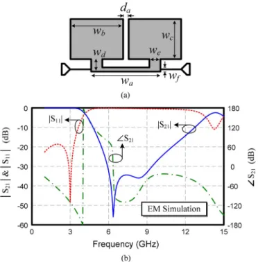
Fig. 1(a) shows the physical layout of microstrip bandstop structure, which is composed of a series high-impedance line and two low-impedance shunt stubs. It should be noted that an edge coupling between two low-impedance shunt stubs has been introduced to create an extra transmission zero so as to give better selectivity and wider stopband. Moreover, due to the ca-pacitive loading effect of two low-impedance shunt stubs, the bandstop structure shows the slow-wave characteristic to reduce the circuit size.
As shown in Fig. 1 (b), the frequency responses of this band-stop structure exhibit a band-stopband ranging from 4.8 to 12.74 GHz with a rejection level better than 10 dB. As a result, a bandstop embedded resonator may be formed by embedding the band-stop structure into a 4 resonator. With the rejection band of
1531-1309/$25.00 © 2008 IEEE
390 IEEE MICROWAVE AND WIRELESS COMPONENTS LETTERS, VOL. 18, NO. 6, JUNE 2008
Fig. 1. Proposed microstrip bandstop structure. (a) Physical layout. (w = 6.35 mm,w = 3.683 mm, w = 4.826 mm, w = 1.143 mm, w = 1.016 mm, w = 0.381 mm, d = 0.508 mm). (b) Fullwave simulated frequency re-sponses.
bandstop structure adjusted to suppress the lower spurious har-monics of 4 stepped-impedance resonator, one may imple-ment a compact BPF with its stopband widely extended.
III. FOURTH-ORDERFILTERWITHSTEPPED-IMPEDANCE
RESONATORSCONNECTED TOINPUT/OUTPUT
The circuit configuration of the first proposed fourth-order microstrip filter is shown in Fig. 2, which is fabricated on the Rogers RO4003C substrate with 3.38 0.0022, and thickness 0.813 mm. Specifically, the first and fourth res-onators are composed of the 4 stepped-impedance resonators while the second and third resonators are of the 4 bandstop embedded resonators. Each resonator is folded to achieve re-quired couplings and to make the size compact. It should be mentioned that extra stepped-impedance lines have also been introduced and connected to the bandstop structure so as to es-tablish the second and third 4 bandstop embedded resonators as shown in Fig. 2.
The proposed fourth-order filter is designed using the cou-pled-resonator procedures [12]. The design parameters of this fourth-order filter are determined for the Butterworth response with the center frequency at 1.5 GHz and a fractional band-width of 10%. The external quality factor and coupling co-efficients associated with the specifications are
To determine the physical dimensions of the filter, the full-wave simulator ADS Momentum is employed to establish the required design curves for external quality factor and coupling coefficients.
Fig. 2. Circuit layout of the proposed fourth-order microstrip filter with stepped-impedance resonators connected to input/output. (Via diameter = 1 mm,w = 11.3 mm, w = 8.636 mm, w = 2.286 mm, w = 4.826 mm, w = 3.683 mm, w = 0.381 mm, w = 3.302 mm, w = 3.81 mm, w = 0.889 mm, w = 1.27 mm, d = 0.254 mm, d = 4.191 mm, d = 4.318 mm,d = 2.54 mm, d = 0.508 mm, d = 0.762 mm, d = 0.635 mm, andd = 2.286 mm).
Fig. 3. Simulated and measured frequency responses of the proposed fourth-order microstrip filter (Fig. 2) with stepped-impedance resonators connected to input/output.
Fig. 3 shows the measured and simulated responses of the first fourth-order filter with stepped-impedance resonators con-nected to input and output (see Fig. 2). The measured center frequency is at 1.5 GHz and the measured 3 dB fractional band-width is 10.3%. The implemented filter has an insertion loss lower than 2.424 dB and a minimum return loss of 9.2 dB within the passband. As can be seen from the wideband responses, this filter has a wide stopband up to 14.3 GHz (9.53 ) with a re-jection level over 28.19 dB. Note that a peak around 4.9 GHz with a quite low level of 38 dB is observed to associate with the first harmonic frequency of the bandstop embedded res-onators as depicted in Fig. 3, however its effect is not signif-icant. The circuit size of this fabricated fourth-order filter is 10.414 mm 42.672 mm, which is approximately 0.085 0.349 , where is the microstrip guided wavelength on the substrate at center frequency.
IV. COMPACTFOURTH-ORDERFILTERWITHBANDSTOP
EMBEDDEDRESONATORSCONNECTED TOINPUT/OUTPUT
To save the circuit size, another compact fourth-order mi-crostrip filter is implemented by exchanging the positions of
KUO et al.: WIDE-STOPBAND MICROSTRIP BANDPASS FILTERS 391
Fig. 4. Circuit layout of the proposed compact fourth-order microstrip filter with bandstop embedded resonators connected to input/output. (Via diameter = 1 mm, w = 3.683 mm, w = 4.826 mm, w = 6.35 mm, w = 9.398 mm, w = 3.937 mm, w = 1.016 mm, w = 0.381 mm, w = 1.524 mm, d = 0.381 mm, d = 4.318 mm, d = 0.889 mm, d = 0.889 mm,d = 2.794 mm, d = 0.762 mm, and d = 0.508 mm).
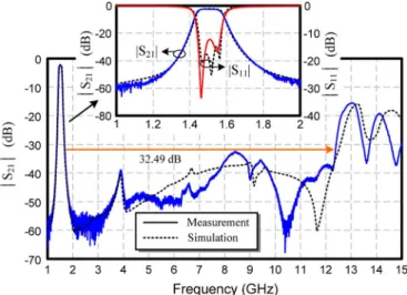
Fig. 5. Simulated and measured frequency responses of the proposed fourth-order microstrip filter (Fig. 4) with bandstop embedded resonators connected to input/output.
the 4 stepped-impedance resonators and the bandstop em-bedded resonators. Fig. 4 shows the circuit layout of the pro-posed compact fourth-order filter, which is also designed for the Butterworth response with the center frequency at 1.5 GHz and a fractional bandwidth of 10%. Specifically, although the feeding method associated with these bandstop embedded resonators is different from that of Fig. 1(a), the first and fourth resonators still have the bandstop behavior.
The measured and simulated responses of the proposed compact fourth-order filter (see Fig. 4) are shown in Fig. 5. The implemented compact fourth-order filter has the measured center frequency at 1.508 GHz, a measured 3 dB fractional bandwidth of 10%, a minimum insertion loss of 2.35 dB, and a return loss of 14.85 dB. Its stopband is extended up to 12.38 GHz (8.25 ) with an adequate rejection greater than 32.49 dB. This fabricated fourth-order filter has a compact
dimension of 10.922 mm 33.02 mm, which is approximately 0.089 0.27 .
V. CONCLUSION
In this letter, two novel fourth-order microstrip filters using 4 stepped-impedance resonators and bandstop embedded resonators have been realized and carefully examined. By combining the advantages of stepped-impedance resonators and bandstop structures, that is, pushing the spurious harmonics higher and providing a certain rejection band, two BPFs with wide-stopband feature and without any extra component are achieved. Moreover, since both 4 stepped-impedance res-onators and bandstop embedded resres-onators are smaller in sizes, the proposed filters have compact circuit dimensions. The implemented compact fourth-order filter (Fig. 4) has the merits of compact size and good performance when compared with the previously fabricated wide-stopband filters.
REFERENCES
[1] K. F. Chang and K. W. Tam, “Miniaturized cross-coupled filter with second and third spurious responses suppression,” IEEE Microw.
Wire-less Compon. Lett., vol. 15, no. 2, pp. 122–124, Feb. 2005.
[2] J. Gu and X. Sun, “A compact C-CMRC feeding open-loop resonator for harmonic rejection bandpass filter,” Electron. Lett., vol. E89-C, no. 9, pp. 1635–1367, Sep. 2006.
[3] W. H. Tu and K. Chang, “Compact second harmonic-suppressed bandstop and bandpass filters using open stubs,” IEEE Trans. Microw.
Theory Tech., vol. 54, no. 6, pp. 2497–2502, Jun. 2006.
[4] A. Manchec, C. Quendo, E. Rius, C. Person, and J.-F. Favennec, “Syn-thesis of dual behavior resonator (DBR) filters with integrated low-pass structures for spurious responses suppression,” IEEE Microw. Wireless
Compon. Lett., vol. 16, no. 1, pp. 4–6, Jan. 2006.
[5] C. H. Wang, P. H. Deng, and C. H. Chen, “Coplanar-waveguide-fed microstrip bandpass fitlers with capacitively broadside-coupled struc-tures for multiple spurious suppression,” IEEE Trans. Microw. Theory
Tech., vol. 55, no. 4, pp. 768–775, Apr. 2007.
[6] J. T. Kuo, M. Jiang, and H. J. Chang, “Design of parallel-coupled mi-crostrip filters with suppression of spurious resonances using substrate suspension,” IEEE Trans. Microw. Theory Tech., vol. 52, no. 1, pp. 83–89, Jan. 2004.
[7] T. Lopetegi, M. A. G. Laso, F. Falcone, F. Martin, J. Bonache, J. Garcia, L. Perez-Cuevas, M. Sorolla, and M. Guglielmi, “Microstrip “wiggly-line” bandpass filters with multispurious rejection,” IEEE
Microw. Wireless Compon. Lett., vol. 14, no. 11, pp. 531–533, Nov.
2004.
[8] S. G. Mao and Y. Z. Chueh, “Coplanar waveguide bandpass filters with compact size and wide spurious-free stopband using electromagnetic bandgap resonators,” IEEE Microw. Wireless Compon. Lett., vol. 17, no. 3, pp. 181–183, Mar. 2007.
[9] C. F. Chen, T. Y. Huang, and R. B. Wu, “Design of microstrip band-pass filters with multiorder spurious-mode suppression,” IEEE Trans.
Microw. Theory Tech., vol. 53, no. 12, pp. 3788–3793, Dec. 2005.
[10] S. C. Lin, P. H. Deng, Y. S. Lin, C. H. Wang, and C. H. Chen, “Wide-stopband microstrip bandpass filters using dissimilar quarter-wavelength stepped-impedance resonators,” IEEE Trans.
Microw. Theory Tech., vol. 54, no. 3, pp. 1011–1018, Mar. 2006.
[11] M. Makimoto and S. Yamashita, “Bandpass filters using parallel cou-pled stripline stepped impedance resonators,” IEEE Trans. Microw.
Theory Tech., vol. MTT-28, no. 12, pp. 1413–1417, Dec. 1980.
[12] J. S. Hong and M. J. Lancaster, Microstrip Bandpass Filters for
RF/Mi-crowave Applications. New York: Wiley, 2001, ch. 8 and 10.