Pergamon
Inr. J Heor Mass Transfer. Vol. 39, No. 15. pp. 3193-3210, 1996 Copyright 0 1996 Elsevier Science Ltd Printed-in &eat Britain. All rights reserved
0017-9310/96$15.00+0.00 0017-9310(95)oo4o4-1
A combined numerical and experimental study
of air convection in a differentially heated
rotating cubic cavity
Y. T. KER and T. F. LINtDepartment of Mechanical Engineering, National Chiao Tung University, Hsinchu, Taiwan, Republic of China
(Received 23 Augur 1995 and inJinalform 6 November 1995)
Abstract-A combined numerical and experimental study was carried out to investigate the steady con- vective flow structure and the flow stability in an inclined cubic air cavity subject to differential heating across a pair of side walls and subject to rotation about an axis which is normal to the insulated bottom wall and through the geometric center of the cavity. In the numerical simulation the three-dimensional Navier-Stokes and energy equations were directly solved by the projection method for the vertical cavity (4 = 0”). While in the experimental study the air temperature in the cavity at selected locations was detected for both steady and unsteady flows. Results were obtained for AT = 10°C and 4.6”C, n from 0 rpm to 453 rpm and 4 from 0” to 75”. The numerical results clearly revealed the complex multicellular flow structure in a vertical cavity at low rotation rates in which the mutual interactions of the thermal buoyancy, Coriolis force and rotational buoyancy are important. The experimental data suggested that the air flow can be stabilized by the cavity rotation when the rotation rate is low. But at high rotating speed the cavity rotation
produced destabilizing effects. Copyright 0 1996 Elsevier Science Ltd.
1. INTRODUCTION
This study is motivated by the fact that rotation can exhibit profound influences on the convection in a rotating air cavity subject to differential heating, when the associate Coriolis and centrifugal forces are in comparable magnitudes with the thermal buoyancy. However, the details on how these interactive forces act on the complex resulting flow are still poorly understood. The effects of the centrifugal force, which are often ignored in the literature, need to be accounted for herein, since it can significantly modify the rotating flow of a variable density fluid resulting from the temperature nonuniformity. This is named as the ‘rotational buoyancy’. The governing nondimensional groups characterizing the thermal buoyancy, Coriolis force and rotational buoyancy for the rotating air cavity flow under investigation are, respectively, the thermal Rayleigh number Ra ( = j?g A TIP/w), Taylor
number Tu (= @H’/v’) and rotational Rayleigh num- ber Ra, ( = /?Q2 ATfl/va). It is, however, realized that for a cavity of fixed size the flow in it is governed by only two physical parameters-the rotation rate R and temperature difference AT. This simply indicates that the three nondimensional groups are inter- dependent and their values can not be arbitrarily assigned. Thus, the parametric study of the flow through numerical simulation in our previous inves- tigation by Lee and Lin [I] can only provide the phys-
t Author to whom correspondence should be addressed.
its of flow, but is not in accord with the practical situation. In this investigation a combined numerical and experimental study was carried out to explore the temperature difference and rotation rate on the detailed flow and thermal characteristics of the air convection in a cubic cavity. Attention was mainly focused on the steady three-dimensional flow and thermal structures in the numerical simulation. While in the experimental measurement the time variations of the air temperature were measured to provide the data for verifying the numerical results and to study the effects of the rotation on the stability of the flow. In the literature considerable attention has been paid to the convection in a bottom heated, infinite bounded horizontal layer of fluid rotating at a con- stant angular speed about a vertical axis [Z-8]. From linear stability analysis, Niller and Bisshopp [2] noted that in the limit of a large Taylor number the viscous effects play an important role in a thin layer near the boundary and the critical Rayleigh number Ra, for the onset of convection is independent of whether the boundaries are rigid or free. Numerical analysis conducted by Veronis [3] indicated that the Prandtl number exhibits significant effects on the flow and thermal structures. For the limit of infinite Prandtl number Kiippers and Lortz [4] showed that no stable steady-state convective flow exists if the Taylor num- ber exceeds a certain critical value. Rossby [S] exper- imentally observed the subcritical instability in a water layer for Ta > 5 x lo4 and in an air layer for Tu < IO’. In addition, for water at Ra > IO4 the Nusselt number was found to increase with the Taylor number. The 3193
3194 Y. T. KER and T. F. LIN
NOMENCLATURE
9 magnitude of the gravitational
acceleration
g gravitational acceleration
H length of cavity
NU local Nusselt number
Nu space-average Nusselt number
Nu: Y-direction average Nusselt
number
P, motion pressure
Pr Prandtl number
r position vector
RU Rayleigh number
RU,. rotational Rayleigh number
t time
T local temperature
Ta Taylor number
Tfi temperature of the hot wall
T, temperature of the cold wall
To initial fluid temperature, r,, = 0.5 (TH+ T,.)
11, ~1. IV dimensional velocities in .v, J‘. ; directions
Cl, V. W dimensionless velocities in X. Y. Z directions
I ~‘/ln,Y> I VI.,,,, I WI,,, maximum
dimensionless velocity magnitudes in X. Y, Z directions
V velocity vector
X, _r, 2 dimensional coordinate systems
X. Y. Z dimensionless coordinate systems.
Greek symbols ;
thermal diffusivity
thermal expansion coefficient
ST amplitude of temperature oscillation
b T,, amplitude of temperature oscillation for 4 = 75’~ and Q = 0 rpm
AT temperature difference between the hot
and cold walls
0 dimensionless temperature
\ kinematic viscosity
/) air density at temperature T
PI, air density at temperature To ;
dimensionless time
inclined angle between gravity and rotating axis
R magnitude of rotating rate
R rotating rate.
opposite trend is the case for air. Besides. at a large Taylor number the oscillatory convection is preferred in mercury. Based on the mean-field approximation, Hunter and Riahi [6] analytically showed the non- monotonic variation of the Nusselt number with the Taylor number. Linear stability analysis from Rud- raiah and Chandna [7] indicated that the critical Ray- leigh number was relatively sensitive to the method and rate of heating, Coriolis force and the nature of the bounding surfaces of the fluid layer. The analysis from Clever and Busse [8] suggests that the critical Rayleigh number for the onset of oscillatory motion is higher for the higher Taylor and Prandtl numbers.
Another geometry of considerable interest is the flow in a bottom heated vertical closed circular cyl- inder rotating about its axis. Experiments for silicone oil carried out by Hudson and his coworkers [9, IO] indicated that the Nusselt number increases with the
rotation rate. Steady axisymmetric numerical simu-
lation was carried out by Chew [l 11. The onset of
steady natural convection was shown by Buell and
Catton [12] to be rather sensitive to the lateral thermal boundary condition. Pfotenhauer et al. [ 131 reported experimental results for the effects of the cylinder geometry on the onset of convection for the low tem- perature liquid helium. For water subject to the Ray- leigh number ranging from 10h to 2 x 10” and Taylor
number from IO6 to IO”, Boubnov and Golitsyn [14]
experimentally observed a ring pattern of convective flow resulting from the fluid spin-up and vertex inter-
actions between two adjacent vortices. Kirdyashkin and Distanov [ 151 found that a periodically changing rotation speed can result in periodical temperature changes throughout the entire liquid layer.
Experimental data for the Nusselt number in a top heated horizontal rectangular cavity of silicone oil rotating about a vertical axis passing through the geo- metric center of the cavity were presented by Abel1 and Hudson [ 161. Hathaway and Somerville [ 171 con-
ducted a three-dimensional and unsteady numerical
simulation of an inclined rotating layer, with the rotation vector tilted from the vertical. The tilting of the rotation vector was found to produce significant change in the flow structure. A combined theoretical,
numerical and experimental study was presented by
Btihler and Oertel [18] to investigate thermal con- vection in rotating rectangular shallow box heated from below. First, linear stability analysis was used to predict the onset of steady and oscillatory convection
and three-dimensional flow configuration. Then, the
numerical analysis predicted the change of the roll orientation with the Taylor number. Finally, the flow structures at various Rayleigh and Taylor numbers were visualized. Unusual flow circulation was exper- imentally observed by Condie and Griffiths [ 191 for a horizontal layer of water.
The above literature review indicates that the early studies mainly focused on the effects of the rotation on the onset of convection and the overall heat transfer at
Air convection in a rotating cubic cavity 3195 cesses on how the Coriolis and centrifugal forces affect
the convective flow structure and its stability in a differentially heated cavity are still not well under- stood. In this study, a combined three-dimensional numerical simulation and experimental measurement was carried out to enhance our understanding on the differentially heated rotation cavity flow.
2. MATHEMATICAL MODELING AND SOLUTION METHOD
and thermal buoyancy. By adopting the generalized Boussinesq approximation [20], in which the linear density variation with the temperature is considered in both the body force and centrifugal force terms, the thermal and rotational buoyancies and Coriolis force acting on the flow are, respectively, equal to - p&?( T- T,), p,#( T- T&k x S2 x r and -2p@ x v, where r is the position vector (x, y. z) defined on the rotating coordinate system. The driven flow in the rotating cavity can be described by the following basic equations :
2.1. Mathematical model
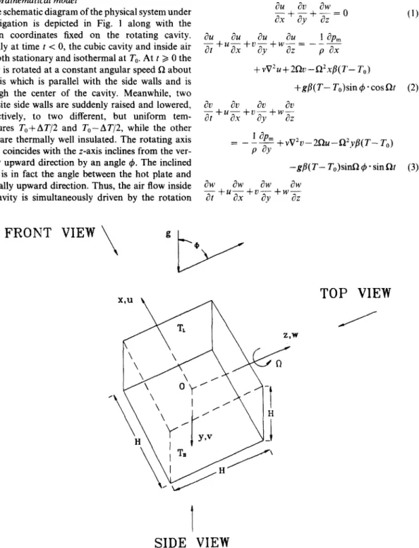
The schematic diagram of the physical system under investigation is depicted in Fig. 1 along with the
!%+&+!!LO
ax ay aZ
(1)chosen coordinates fixed on the rotating cavity. Initially at time t < 0, the cubic cavity and inside air are both stationary and isothermal at T,. At t > 0 the cavity is rotated at a constant angular speed Q about an axis which is parallel with the side walls and is through the center of the cavity. Meanwhile, two opposite side walls are suddenly raised and lowered, respectively, to two different, but uniform tem- peratures Tot-AT/2 and To-AT/2, while the other walls are thermally well insulated. The rotating axis which coincides with the z-axis inclines from the ver- tically upward direction by an angle 4. The inclined angle is in fact the angle between the hot plate and vertically upward direction. Thus, the air flow inside the cavity is simultaneously driven by the rotation
au
auau
au
1
ap,
T&+“~+“ay+wat= -pax +vV2u+2Ru-R2x/9(T-T,,) +gB(T- T,)sin 4 * cos Qt (2) = - fe +vV2u-2Qu-Q2y/l(T- T,,) -g@( T- T,,)sinR 4 - sin Clt (3)aw
aw
aw
awdt+Uax+u&+Wz
FRONT VIEW
\
gpy
TOP VIEW
SIDE VIEW
3196 Y. T. KER and T. F. LIN where _
1
ijpm paZ
+vV2M’+g~(T-T”)cos~ aT dT ST ZT ‘t+~~+v~+w~=c~V~T 0’ 2and pm is the motion pressure defined as
JPm JP dx - -z +p,n’s-p,gsin~.cosRr. ?P’p, c?\ - - $ +p,,R’?‘+p”gsin~.sinnr and (4) (5)
This indicates that the hydrostatic pressure and the centrifugal force acting on the fluid at the referenced density p. are absorbed in the motion pressure p”,. The three velocity components u, u and w are defined on the coordinates s, _r and z rotating with the cavity. as shown in Fig. 1. Note that the third and fourth terms on the right hand side of equations (2) and (3). respec- tively, denote the momentum change of the flow due to the Coriolis force and the centrifugal force on a
variable density fluid subject to temperature non-
uniformity. The corresponding initial and boundary conditions are
t < 0, II = z’ = w = 0 and T = T,, for all _v.?‘, z
t > 0. _y = - H 2‘ u zz 1‘ = 1,’ = 0, T= T,,- “2’ H SE -~ 2’ u=(-=M.=O, T = TO + !; J=*” dT 2’ u=r,=,r=O, -=O P_b u = (’ = )I‘ = 0, -- ?T ?z =O. (6)
The results from the computation are to be pre- sented in terms of the following nondimensional vari- ables :
X = x/H, Y = J’iH. Z = z/H, 5 = t/(H’/a).
U = u/(a/H). C’ = L,i(a/H), W = w/(aiH)
0 = (T- T,)/AT. P = pmi(pa’/HZ), Pr = v/a
Ra = gpATH’/(va), Ra,, = Q’HbATH’/(va).
Ta = Q’H”/v’. (7)
Note that for the rotating cavity flow Ra, =
Ra*(O*H/g) and Raw = TaQAT*Pr). Also note that
the values of (/I * Pr) for the gas and liquid at the same temperature do not differ significantly. Hence, the
rotational buoyancy becomes important for a high
rotating speed, large cavity dimension or large tem- perature difference.
In addition to examining the time evolution of the velocity and temperature fields. results for the local. J’- direction average and space-average Nusselt numbers Nu, Nul and z on the heated or cooled plates are important in thermal design and can be evaluated from a0 Nu= --
ax
,y=io 5(8)
-I
05 NM, = NudY (9) -0 5 - Nu; = NudYdZ. (10) 2.2. Solution methodThe basic equations for the present three-dimen-
sional unsteady rotating cavity flow were solved
numerically. In particular, the power-law scheme [21] was used to discretize equations (l)-(5) on a non- uniform staggered grid system with the pressure and temperature defined at the mesh centers. The resulting finite difference equations were solved by the pro- jection method [22]. The detailed solution procedures were described in our earlier work [ 11.
In view of the complex flow to be simulated, strin- gent program tests have been conducted to verify the proposed solution method [I]. First, computations were carried out for the limiting case of a nonrotating (0 = 0) vertical cavity. Our predicted steady local Nusselt numbers for various cases are in good agree- ment with the results of Bauman et al. [23], De Vahl Davis [24], Bajorek and Lloyd [25] and Hamady [26]. Next, tests were performed for a rotating cavity. Our predictions were compared with the experimental data
of Hamady [26] with reasonable agreement. Fur-
thermore, results for the transient variation of the
space-average Nusselt numbers on the hot wall NM
were compared with those from Kuwahara et al. [27]
for Ra = IO4 and lo6 in a nonrotating cavity. Good
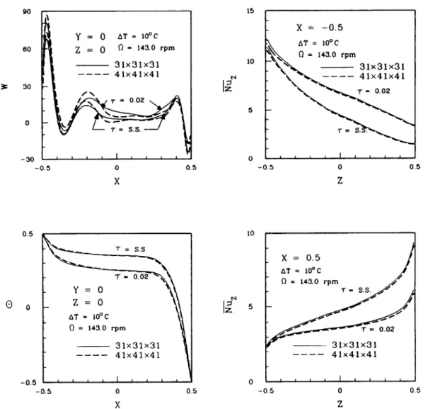
agreement is noted over the entire transient. Good agreement is also noted for other flow and thermal characteristics. Finally, grid-independence tests were conducted for a number of cases. Results from such tests indicated that the differences in the predicted maximum local velocity magnitudes 1 UI,,,, 1 VI,,, and 1 WI,,, from the 30 x 30 x 30 and 40 x 40 x 40 grids are all less than 4.2% during the entire transient. Better agreement is obtained for Nu. The differences in Nu predicted from these two grids are within 1% during the entire transient. Furthermore, comparison of the velocity and temperature profiles also showed good
Air convection in a rotating cubic cavity 90 I\ 1 60
is
30 0 y = 0 AT = 10°C n - 143.0 rpm -30 - 0 -0.5 0 0.5 -0.5 0 0.5 X Z 10 I$ 5 0.50
0 -0.5z=o
AT = 10°C t-l = 143.0 rpm ~ 31X31X31 ---- 41X41X41 10 0x =
0.5 AT = 10°C n = 143.0 rpm _Fig. 2. Comparison of the numerically predicted velocity and temperature profiles along the X-direction at line Y = 0 and Z = 0 and the Y-direction averaged Nusselt number calculated from two different grids for
AT = lo”C, I#J = 0” and n = 143 rpm at two time instants.
agreement. To exemplify this comparison, results for a case with R = 143 rpm, AT = 10°C and 4 = 0” are shown in Fig. 2. Good agreement is noted in the velocity and temperature profiles computed from the two different grids over the entire transients. Through these tests, the proposed numerical method is con- sidered to be suitable for the present problem.
3. EXPERIMENTAL APPARATUS FOR
TEMPERATURE MEASUREMENT
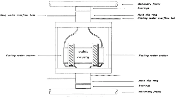
The experimental system for measuring the thermal characteristics in a rotating air cavity schematically shown in Fig. 3 consists of four parts-rotating frame, test section, temperature control unit and temperature measuring unit. Figure 4 shows the details of the test section.
The rotating frame is made up of a rotary table of 3 1.5 cm in diameter and is mounted on a steel shaft of 3 cm in diameter. The frame is designed to provide
a space of 27.6 cm in diameter and 27.3 cm in height for housing the test section. The shaft is rotated by a 2 horse power dc. motor with its speed controlled by an inverter. Besides, the rotating speed is detected by a photo-electric tachometer. Care is taken to ensure that the table rotates centrally and steadily.
The test section fixed on the rotating table is a cubic air enclosure of 10 cm in length. Two opposite walls of the cavity made of 2.5 mm thick copper plates were controlled at uniform, but different temperatures by circulating constant temperature coolants through them. Two fluid sliprings were used to allow the cool- ants to pass from the stationary thermostats to the rotating cavity. The thermostats used are the LAUDA RK-20 compact constant temperature baths with a temperature range of -4&l 50°C and a resolution of 0.1% Care must be taken to prevent the coolant leak from the fluid sliprings. The other walls were made of 10 mm thick acrylic plates and were thermally insu- lated by the super-lon foam. Through this arrange-
3198 Y. T. KER and T. F. LIN 11 _. 12
iI
12l-
5r
16@-I
0
0 1 : 2 : 3 : 4 : 5 : 6 : 7 : 8 :test section 9 : platform
fluid slip ring 10 : slip ring
supporting frame 11 : thermocouples
rotating frame 12 : thermostat
statatic frame 13 : data acquisition system
photo - electric tachometer 14 : digital multimeter
2 Hp induction motor 15 : P.C. computer
inverter 16 : laser printer
Fig. 3. Schematic diagram of the experimental system.
e-
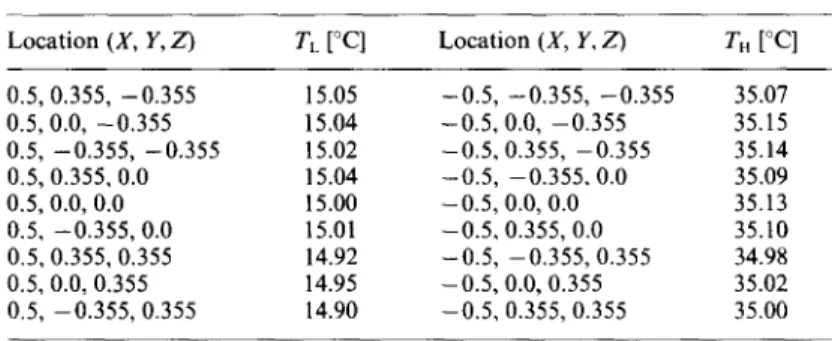
Air convection in a rotating cubic cavity 3199 Table 1. Uniformity of the isothermal walls
Location (X, Y, Z) TL [“Cl Location (X, Y, Z) TH
[“Cl
0.5, 0.355, -0.355 15.05 -0.5, -0.355, -0.355 35.07 0.5,0.0, -0.355 15.04 -0.5. 0.0, -0.355 35.15 0.5, -0.355, -0.355 15.02 -0.5,0.355, -0.355 35.14 0.5,0.355.0.0 15.04 -0.5, -0.355.0.0 35.09 0.5,0.0, 0.0 15.00 -0.5,0.0, 0.0 35.13 0.5. -0.355,o.o 15.01 -0.5,0.355, 0.0 35.10 0.5,0.355, 0.355 14.92 -0.5, -0.355,0.355 34.98 0.5, 0.0, 0.355 14.95 -0.5,0.0,0.355 35.02 0.5, -0.355, 0.355 14.90 -0.5, 0.355, 0.355 35.00ment the temperature uniformity of the isothermal
plates can be controlled to within IfrO.l”C. The sam- pled measured data for the temperature of the hot and cold walls at selected locations are given in Table 1.
cavity rotating at various rotation rates and subject to various temperature differences across a pair of opposite side walls.
The temporal and spatial variations of the air tem- perature in the rotating cavity were measured by directly inserting thermocouples of T-type into the cavity. The thermocouples are fixed at the designated locations by the high performance fine Neoflon thread, which is in turn fixed across a pair of opposite side walls. Prior to installation the thermocouples were calibrated by the LAUDA thermostats and high precision liquid-in-glass thermometers. The voltage signals from the thermocouples were passed through a slip ring to the HP 3852 A data acquisition/control system and then to a personal computer for further data processing. Data collection is normally started when the flow already reaches steady or statistical state. In view of the flow being at low speed and the cavity being rotated, velocity measurement is difficult and is not conducted here.
4.1. Flow structures at various rotation rates in vertical cavity
The test was started by first setting the temperatures of the thermostats at the predetermined values and then recirculating the coolants through the isothermal walls of the rotating cavity. The mean value of the hot and cold plate temperatures was chosen to be equal to the ambient temperature, so that the heat loss from the cavity to the ambient can be reduced. In the mean- time the cavity was rotated at the predetermined speed. Then the temperature of the air inside the cavity was measured at selected locations. After the transient stage has elapsed, the data for the steady or statistical state were sorted and analyzed.
For comparison purpose the numerically predicted steady thermal and flow structures for the limiting case of the nonrotating cavity (Q = 0) with
Ra = 9.43 x 10’ (or AT = 10°C and H = 10 cm) and 4 = 0” are given in Fig. 5 in which the velocity vector maps and isotherms in selected planes from the front, side and top views are plotted. The flow for this case is centrosymmetric and is characterized by a strong recirculation rising from the hot plate and sinking near the cold plate with weak recirculation near the vertical central plane parallel to the isothermal walls at X = 0 and near the horizontal middle plane at Z = 0, as evident from the front and top views (Fig. 5). Thermal boundary layers exist in the regions near the hot and cold walls and stable thermal stratification prevails in the cavity core. Complete details of the flow in a stationary cavity can be found in our earlier study [28]. Now as the cavity is rotated at 30.7 rpm with other parameters fixed at the same values as the previous case, the resulting steady flow from the numerical computation is shown in Fig. 6. Con- trasting these results with those in Fig. 5 for the non- rotating cavity indicates that at this rotation rate the
Table 2. Summary of uncertainty analysis The ranges of the governing parameters to be inves-
tigated are as follows : the rotating speed varied from 0 to 453 rpm, the inclined angle from 0” to 75” and the temperature difference across the cavity from 2 to 10°C for a cavity of 10 x 10 x 10 cm3. The uncertainty analysis of the measurement was summarized in Table 2.
4. RESULTS AND DISCUSSION
In the following only a small sample of the results from the present study will be presented here to illus- trate the flow and thermal characteristics in an air
Parameters H (m) THY TL TH. TL T (Thermocouples) a (m* s-‘) B (Km’) p0 (kg mm3) v (m* s-‘) Q (rpm) 4 (degree) Tll Ra Ra, Uncertainty f 0.0005 m f 0.1 “C (non-rotating) f 0.2”C (rotating) +o.o5”c ?0.07% &0.05% f 0.05% ?0.07% f0.3% f0.5” + 10.5% k2.5% k11.5%
3200 Y. T. KER and T. F. LIN
Vnax = 67.85
vnox
= 41.05 vnox = 83.11 front view left to right: x=-O.2890 x=0.0 x=0.2890 2I
I
y
side view left to right: Vnax = 200.1 . . . . . , . . . . . , . . . . . . . . . . . . . . . ) Y =-0.2890 Y =o.o TC . “., Y =0.2890 TH TC vnax = 195.7 ,..____<_ - .---.., - . . . . ... ‘.. -0.45~0.10)0.45 e g 8 f. G t- X VWJX = 137.5 top view left to right: Z=-0.2890 TH z=o.o Z =0.2890 Y I Vnox = 56.01 (b)--t-x
(0) Fig. 6. The velocity vector maps (a) and isotherms (b) in selected planes for I$ = 0 ’ AT = 10°C and fi = 30.7 rpm at steady state (Ra = 9.43 x 10⁵, Ta = 4.62 x 10⁶, Ra, = lo ’, , 4 = 0”).3202 Y. T. KER and 7. F. LIN
main flow, clearly seen from the side view, is weakened to a certain degree by the cavity rotation with the accompanying much stronger flow recirculation in the horizontal planes (top view) and in the planes parallel with the hot plate (front view). This speedup of the cross plane secondary flow modifies the temperature contours significantly [Fig. 6(b)]. The core flow is no longer thermally stably stratified. This significant flow modification at this low rotation rate can be under- stood by checking the governing dimensionless groups corresponding to this case. The values of the par-
ameters for this case are Ru = 9.43 x 10⁵,
Tu = 4.62 x IO6 and Ro, = IO’. Hence, the Coriolis force (Taylor number) is so high that it exerts an important effect on the thermal buoyancy driven flow [ 11. Moreover, the flow is no longer centrosymmetric for this case. Raising the rotation rate from 30.7 rpm to 97.4 rpm with AT still fixed at 10°C results in the increase in the Ta and Ra, by 10 times, and thus we have Ru = 9.43 x lo’, Tu = 4.62 x 10’ and Ru, = 106.
The numerically predicted steady flow and tem-
perature fields for this case shown in Fig. 7 indicate that the driven flow does not close to that driven by the thermal buoyancy, rotational buoyancy or Cori- ohs force alone [I]. although the flow structure view- ing from the top possesses some characteristics of the
centrifugal force dominated flow, which is char-
acterized by a pair of vertical vortex rolls. This is conjectured to be the consequence of the comparable magnitude of the Ra, Ra, and Ta in the flow and there are strong interactions among them. Also note that at this higher rotation rate the flow is significantly suppressed, as evident from comparing Figs. 6 and 7.
Results were also obtained for H = 10 cm and
AT = 4.6’C and 2’ C at various rotation rates. A simi-
lar trend was noted from these results.
4.2. Ejjkcts of rotution rate on the velocity und tem-
perature prqfiles
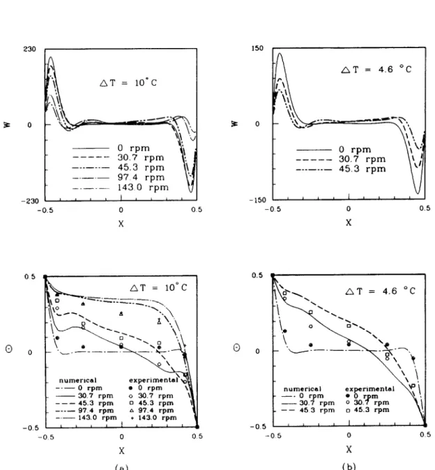
The numerically predicted deceleration of the main recirculation of the thermal buoyancy driven flow. and the thickening of the velocity and thermal boundary layers on the hot and cold walls by the cavity rotation, are illustrated by examining the steady vertical vel- ocity and temperature profiles on a horizontal line at Y = 0 and Z = 0 at the midheight of the cavity given in Fig. 8 for AT = 10°C and 4.6”C for various 0. The measured data for the air temperature from the present study are also included in the plots. Larger flow slowdown by the higher rotation rate is clearly seen from these results. The gradual disappearance of the dips in the temperature profiles at increasing rotation rate is also observed. The calculated tem- perature profiles agree reasonably with the measured data, except at high rotation rates. 12 = 97.4 rpm and 143 rpm. At these high rotation rates the numerical simulation overpredicted the temperature.
4.3. Average Nusselt numbers
The numerically predicted Y-direction average
Nusselt numbers Nu, on the hot and cold walls are
presented in Fig. 9 for AT = 10°C and 4.6”C for 4 = 0” at various rotation rates. The results clearly show the reduction of convective heat transfer from the walls to the air by the cavity rotation especially in the high heat transfer regions near the leading edges of the boundary layers on the isothermal walls. At high rotation rates the heat transfer near the upper left and lower right corners of the cavity can be slightly enhanced by the rotation.
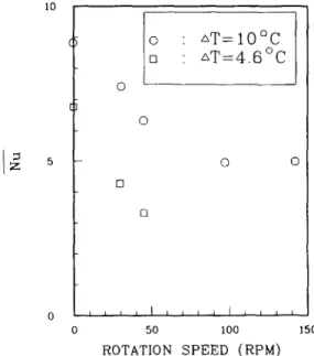
Finally, the numerically computed space-average
Nusselt numbers Nu on the isothermal walls at various R are displayed in Fig. 10 for AT = 10°C and 4.6”C for 4 = 0“. The results suggest that at low rotation rate (Q < 50 rpm) significant heat transfer reduction by the cavity rotation occurs, but at high rotation rate (a > 100 rpm) rotating the cavity does not further reduce the heat transfer for AT = 10°C. In fact, a slight increase in NM may result from raising the rotation rate over 100 rpm.
4.4. Rotation induced jlow stabilization or destu-
bikution
In the present study the stabilizing or destabilizing effect of the buoyancy driven flow by the cavity rotation are investigated by examining the time vari- ations of the measured air temperature at selected locations in the cavity. Only the long term results are studied at which the temperature already reaches steady or statistical state.
Results are first presented for the vertical cavity (4 = 0”). When the cavity is stationary (0 = 0) the thermal buoyancy driven flow is found to be as steady after initially being transient for all the cases studied
(AT < IOOC), as those from the numerical simulation [28]. Rotating the cavity was found to destabilize the flow when the rotation speed exceeds a certain critical value. Figure 11 shows the sampled data for the time records of the air temperature at various rotation rates at location X = 0.42, Y = 0 and Z = 0 for AT = 10°C and 4.6”C (Ru = 9.43 x lo5 and 4.36x 10⁵). These results clearly suggest that for AT = 10°C the flow is steady at Q < 80 rpm. At this low rotation speed, random oscillations at very small amplitude due to background disturbances are noted. Small amplitude
periodic temperature oscillation was detected at
Q = 97.4 rpm. At R = 143 rpm, high frequency small amplitude oscillation superimposes on the periodic part. The temperature oscillation becomes somewhat irregular and in higher amplitude at Q = 308 and 453 rpm. Similar trend was noted for AT = 4.6”C [Fig. 11 (b)], except that the destabilization is initiated at a lower n and the oscillation amplitude is larger.
Checking the time histories of the air temperature at five different locations in Fig. 12 for s2 = 97.4 rpm for AT = 10 and 4.6”C reveals that the air temperature
at these locations oscillates at nearly the same
frequency, but in different amplitudes. Closer to the hot wall a slightly smaller temperature oscillation is noted. The measured data for a rotating inclined cav- ity with 4 = 30” and 60” also manifest that at small
lir convection in a rotating cubic cavity 3203
I , . . .
C-I
i;
3204 Y. T. KER and T. F. LIN 150 230 , I ___ 0 rpm --- 30.7 rpm --- 45.3 rpm -.-.- 97 4 rpm -.-.- -230 ’ ’ ’ ’ ’ ’ ’ ’ ’ ’ ’ -0.5 0 05 ., t 0.5 LIT = 10°C _ numerical --- 0 rpm - . 30.7 rpm --- 45.3 l-pm ---- _ 97.4 rpm 6 97.4 rpm -.- 143.0 rpm -0.5 -0.5 AT = 4.6 OC AT = 4.6 “C numerical -0.5 0 05 -0 5 0 0.5 X X
(a)
(b)
Fig. 8. Vertical velocity and temperature distributions along the X-direction on the line Y = 0, 2 = 0 for 4 = 0”. at (a) AT = 10°C and (b) AT = 4.6”C at different rotating speeds.
Air convection in a rotating cubic cavity 3205 20 gN z 10 0
I:”
- 0 rpm --- 30.7 rpm - 0 rpm --- 30.7 rpm --- 45.3 rpm __ --- ---_- 143.0 rpm 10 - _.. t ~ 0 rpm .---- 30.7 rpm .--- 45.3 rpm _ AT=4.6”C (a) Z (b) ZFig. 9. Y-direction average Nusselt number distributions on the hot and cold walls for 4 = 0” at (a) AT = 10°C and (b) AT = 4.6”C at different rotation speeds.
0 :
AT=lo’C
? ?: nT=4.6OC
0 0 10 0 0 50 100 150 ROTATION SPEED (RPM)3206 Y. T. KER and T. F. LIN
5: 5:
d
d
a
6
e
f2
s:
w6
i?
3
4 /6
p.
6
I
-z
4k
-5:
-
d
rmmmf
d
8
z
%
d dl0
00 ’ T 09 ’0 00 ’0 OE ’O0
OP ’O 09 ’00
06 ’0 00 ’1 OS ’0 00 ’0 0 OO ’T,..,,:,;(JJ:~
o OO ’T 09 ’000
’0
0
OO ’T OS ’0 00 ’0 I I I II
I I I I I I I I II
I
I
I I I I I I II (JL.0(‘O
”O
”0)
OO ’T OS0 00 ’0a
OO ’T OS ’0 00 ’0(‘0
”O
’ZD
’-1
0
(
z ’ A ’X)Wl~~OI
3208 Y. T. KER and T. F. LIN
z s
d d5: $
d dF
::
d0”
-8 .
-4 t- -8-6
-2
d
s s:
Air convection in a rotating cubic cavity 3209 i
(a)
axcO:O deg ++++I :30 deg /vvvv\:60 deg m :‘75 deg AT= 10°Cm
89 0 0.00 l,,IIlI,I~lilllllll~l’ll’llll~l”l’ 0.00 140.00 280.00 420.00 R (rpm) (b) ClZCXD:O deg +H++:30 deg MMA:60 deg UUEI :75 deg AT=4.6“C BPm
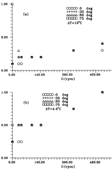
0.00 / 1 I 1 1 1 1 I I f 1 1 I I 1 I I 1 1 11 11 I I 1 I 1 I 1 1 1 1 I I I 0.00 140.00 280.00 420.00 Q (rpm)Fig. 14. The normalized temperature oscillation amplitude for various rotation rates and inclined angles.
rotation rate steady temperature field prevails, but the air temperature becomes time oscillatory for n exceeding certain value, which depends on the inclined angle.
At a higher inclined angle of 75” the resulting flow in a nonrotating cavity (0 = 0) is time oscillatory at larger T for AT = 10°C and 4.6”C. Rotating the cavity is found to yield stabilizing effects on the flow. Specifically the flow oscillation is damped out or sup- pressed to a smaller amplitude by the cavity rotation, as illustrated by the data in Fig. 13. Note that at AT = 10°C a large amplitude irregular temperature fluctuation is detected for Q = 0. At low rotation speed of 30.7 and 45.3 rpm the amplitude of the oscil- lation is much smaller. The temperature oscillation is nearly time periodic at n = 97.4 rpm. At higher R
(= 143 and 308 rpm) small amplitude irregular oscil- lation prevails. Finally, it is also noted from the results that at a higher rotation speed of 453 rpm (Ta = lo9 and Ra, = 2.16 x lo’), the flow is destabilized by the cavity rotation with the oscillation amplitude increased noticeably. A similar trend is noted from the data in Fig. 13(b) for AT = 4.6”C, except that the oscillation amplitude is larger. The above results from the experimental measurement clearly indicate that rotating the cavity does not always produce stabilizing effects on the flow.
The measured data from the present study for the oscillation amplitude of the air temperature 6T at the location (0.42, 0, 0) for various 4 and n when normalized by 6T,, that is the amplitude of the tem- perature oscillation for 4 = 75” and R = 0 rpm are
3210 Y. T. KER and T. F. LIN
presented in Fig. 14 for AT= IO and 4.6-C. The
effects of the cavity rotation on the flow stability are clearly seen from these results.
5. CONCLUDING REMARKS
Through a combined direct three-dimensional
numerical simulation and experimental measurement.
the flow structure and its stability in a differentially heated rotating cavity of air were investigated. The
numerical prediction clearly revealed the complex
multicellular recirculating flow driven by the sim-
ultaneous interactions of the thermal buoyancy and
the centrifugal and Coriolis forces. Besides. significant flow deceleration and heat transfer reduction only occur at low rotation rate. The present experimental data suggested that rotating the cavity results in flow stabilization at low rotation speed. The flow can be destabilized when the cavity is in fast rotation.
During the course of this investigation it is realized
that the effects of the cavity rotation on the flow stab-
ility are particularly important for the cavity flow of
the liquid metal, which is the material for manu- facturing the single wafer for the semiconductor industry. A detailed study on the stability of the rot- ating cavity flow of a low Prandtl number liquid metal is rather important and requires exhaustive explo- ration.
AcknowledqementpThe financial support ofthis study by the
engineering division of National S&&e Council of Taiwan. Reoublic of China through the contract NSC 81-0401 E-
004-548 is greatly appre&ted. The support of the present
computation by the National Center for The High-Per-
formance computing and by the computer center of the
national Chiao Tung University, Taiwan, Republic of China
is also acknowledged.
REFERENCES
1. T. L. Lee and T. F. Lin, Transient three-dimensional convection of air in a differentially heated rotating cubic cavity, Int. J. Heat Mass Transfer 39, 1243-1255 (1996). 2. P. P. Niller and F. E. Bisshopp. On the influence of Coriolis force on onset of thermal convection. J. Fluid
Mech. 22,753%761 (1965).
3. George Veronis, Large-amplitude BCnard convection in
a rotating fluid, J. FluidMech. 31, 113-139 (1968). 4. G. Kiippers and D. Lortz, Transition from laminar con-
vection to thermal turbulence in a rotating fluid layer, J. Fluid Mech. 35,609%620 (1969).
5. H. T. Rossby, A study of BBnard convection with and
without rotation. J. Fluid Mech. 36.309-335 ( 1969). 6. C. Hunter and N. Riahi. Nonlinea; convection in a rot-
ating fluid, J. Fluid Mech. 72,433454 (1975). 7. N. Rudraiah and 0. P. Chandna, Effects of Coriolis force
and nonuniform temperature gradient on the Rayleigh-
Btnard convection. Can. J. Phys. 64,9&99 (1986).
8. R. M. Clever and F. H. Busse, Nonlinear properties of convection rolls in a horizontal layer rotating about a vertical axis, J. Fluid Mech. 94, 609-627 (1979).
9. J. L. Hudson, D. Tang and S. Abell, Experiments on
centrifugal driven thermal convection in a rotating cylin- der. J. FluidMech. 86, 147-159 (1978).
10. D. Tang and J. L. Hudson, Experiments on a rotating
fluid heated from below, In!. J. Heat Mass Transfer 26, 943-949 (1983).
11. J. W. Chew, Computation of convective laminar flow in
rotating cavities. J. Fluid Mech. 153, 339-360 (1985). 12. J. C. Buell and I. Catton, Effect of rotation on the stab-
ility of a bounded cylindrical layer of fluid heated from
below, Ph.vs. Fluids 26,892-896 (1983).
13. J. M. Pfotenhauer, J. J. Niemela and R. J. Donnelly,
Stability and heat transfer of rotating criogens. Part 3. Effects of finite cylindrical geometry and rotation on the onset of convection. J. Fluid Mech. 175, 85-96 (1987).
14. B. M. Boubnov and G. S. Golitsyn, Experimental study
of convective structures in rotating fluid, J. Fluid Mech.
167,503-531 (1986).
15. A. G. Kirdyashkin and V. E. Distonov, Hydrodynamics
and heat transfer in a vertical cylinder exposed to period- ically varying centrifugal forces (accelerated crucible- rotation techniaue), Int. J. Heat Mass Transfer 33, 1397-
1415 (1990). _
16. S. Abel1 and J. L. Hudson, An experimental study of
centrifugally driven free convection in rectangular
cavity, ht. j. Heat Mass Transfer 18, 1415-1423 (1575).
17. D. H. Hathaway and R. C. J. Somerville, Three-dimen-
sional simulations of convection in layers with tilted
rotation vectors, J. Fluid Mech. 126, 75-89 (1983). 18. K. Biihler and H. Oertel. Thermal cellular convection in
rotating rectangular boxes, J. Fluid Mech. 114, 261-282 (1982).
19. S. A. Condie and R. W. Griffiths. Convection in rotating cavity : modeling ocean circulation, J. Fluid Mech. 207, 453474 (1989).
20. G. M. Homsy and J. L. Hudson, Centrifugally driven
thermal convection in a rotating cylinder, J. Fluid Mech. 35, 33-52 (1969).
2 I S. V. Patankar, Numerical Heat Transftir and Fluid Flow.
pp. 90-92 Hemisphere. Washington, DC (1980).
22. M. Fortin. R. Pevret and R. Temam, Lecture Notes in
Physics Vol. 8, pp: 337-342. Springer, New York (1971).
23. F. Bauman. A. Gadgil. R. Kammerud and R. Greif.
Buoyancy-Driven Conoection in Rectangular Enclosures :
E,xperimental Results and Numerical Calculations.
ASME publication 80-HT-66, (1980).
24. G. De Vahl Davis, Laminar natural convection in an
enclosed rectangular cavity. Int. J. Heat Mass Transjtir
11, 1675-1693 (1968).
25. S. M. Baiorek and J. R. Lloyd, Experimental inves-
tigation oi natural convection in partitioned enclosures.
J. Heat Transfer 104.527-532 (1982).
26. F. Hamady, Experimental stuhy of local natural con-
vection heat transfer in inclined and rotating enclosures,
Ph.D. Dissertation, Michigan State University (1987).
27. T. Fusegj. J. M. Hyun, K. Kuwahara and B. Farouk, A
numerical study of three-dimensional natural convection
in a differentially heated cubical enclosure, In/. J. Heat Transfer 34, 1543-1557 (1991).
28. T. L. Lee and T. F. Lin, Three-dimensional natural
convection of air in an inclined cubic cavity, Numer.