行政院國家科學委員會補助專題研究計畫
□期中進度報告
▓期末報告
對焦用音圈馬達之創意設計與定位控制
計畫類別:▓個別型計畫 □整合型計畫
計畫編號:NSC99 - 2221 - E - 020 - MY2
執行期間: 99 年 8 月 1 日至 100 年 7 月 31 日
執行機構及系所:
國立交通大學 機械系
計畫主持人:
呂 宗 熙
共同主持人:
計畫參與人員: 賴隆寬
、
葉仲偉
、
紀佃昀
本計畫除繳交成果報告外,另含下列出國報告,共 1 份:
□移地研究心得報告
▓出席國際學術會議心得報告
□國際合作研究計畫國外研究報告
處理方式:除列管計畫及下列情形者外,得立即公開查詢
□涉及專利或其他智慧財產權,□一年□二年後可公開查詢
中 華 民 國 101 年 9 月 30 日
附件一
國科會補助專題研究計畫成果報告自評表
請就研究內容與原計畫相符程度、達成預期目標情況、研究成果之學術或應用價
值(簡要敘述成果所代表之意義、價值、影響或進一步發展之可能性)
、是否適
合在學術期刊發表或申請專利、主要發現或其他有關價值等,作一綜合評估。
1. 請就研究內容與原計畫相符程度、達成預期目標情況作一綜合評估
▓
達成目標
□ 未達成目標(請說明,以
100 字為限)
□ 實驗失敗
□ 因故實驗中斷
□ 其他原因
說明:
2. 研究成果在學術期刊發表或申請專利等情形:
論文:
▓
已發表 □未發表之文稿 □撰寫中 □無
Lai, L. K. and Liu, T. S., “Design of compact linear electromagnetic actuator
for auto-focusing in phone camera,” Vol. 47, No. 12, pp.4740-4744, IEEE Transactions on
Magnetics, 2011. (SCI, Impact Factor=1.052, RF=90/227=0.466)
專利:□已獲得 □申請中 □無
技轉:□已技轉 □洽談中 □無
其他:(以
100 字為限)
3. 請依學術成就、技術創新、社會影響等方面,評估研究成果之學術或應用價
值(簡要敘述成果所代表之意義、價值、影響或進一步發展之可能性)(以
500 字為限)
音圈馬達是相機鏡頭模組裡的重要元件,擔任致動器的角色。隨著自動對焦、
高倍數變焦、以及攝影技術的進展,對於精準、快速之音圈致動器的需求也越來
越高,因此值得研究音圈馬達的設計與控制。本研究計畫的第一年利用列舉演算
法,基於音圈馬達的特性,以圖論的方式定義,並列出所有的磁路設計,且利用
拓墣矩陣與流值方法,進行刪除同構與比較磁能大小,在磁場分析方面,以有限
元素方法分析音圈馬達之磁場,以達到最佳的致動能力。最後,對磁路中的各個
元件,考慮其不同形狀所造成的磁漏影響,從中選擇最好的磁路設計,並且設計
完成出新的磁路結構之手機相機音圈馬達。
本研究計畫的第二年旨在使音圈馬達線圈的移動時間縮短,移動速度加快。
為此,已經設計了含短路圈之音圈馬達,短路圈位於線圈外側,目的是要大量降
低線圈的電感效應,使線圈的電阻-電感電路作用近乎於電阻電路,使電流響應
更加快速,並使移動線圈能有更大的加速力量。已經針對含短路圈之音圈馬達做
理論推導,並對其系統性能與響應進行電腦模擬。在磁場分析方面,以有限元素
方法分析此音圈馬達之磁場。在定位控制方面,本研究業以狀態回授控制、模糊
控制與順滑模態控制分別對此機構進行補償,進行Matlab軟體的控制模擬與分
析,並使安定時間縮短。已經製作含短路圈之音圈馬達進行定位控制實驗,並利
用雷射位移計測量其位移結果。本國科會計畫的成果已經發表於國際知名期刊
Lai, L. K. and Liu, T. S., “Design of Compact Linear Electromagnetic Actuator for
Auto-focusing in Phone Camera,” Vol. 47, No. 12, pp.4740-4744, IEEE Transactions on
Magnetics, 2011.
國科會補助專題研究計畫出席國際學術會議心得報告
日期:2012 年 9 月 30 日一、 參加會議經過
深夜從桃園搭華航飛機飛往紐西蘭的奧克蘭。十一月二十九日早上六點半抵達紐西
蘭的奧克蘭再轉機抵達
Palmerston North,才體會大會地點交通不太方便,不像一
般國際會議在大城市舉行。議程分四天進行,大會的晚宴邀請原住民歌舞表演,像
是學生團體,不失天真純樸。Massay University 位於郊區,校園清靜純樸,滿眼
不是植物就是綠茵。
我的論文在第三天發表。為了量測物質的折射率,論文所提出的創新方法是利用雷
射繞射儀,將反射的繞射光束與入射光重疊,計算返回光的角度光柵節距和雷射波
長獲得折射率,使用本精密量測方法,可以用來量測水油以及混合粒子的透明液
體。現場有數位德國教授和紐西蘭的學生頗感興趣。對於提問我都一一回答。大會
安排的 Keynote Speaker 有四位,包括印度裔的美國加州理工學院的噴射推進實驗
室資深科學家 Chattopadhyay,演講反恐用途的超高頻雷達,成功大學工程科學系
黃越銘教授,演講以感測器的方法對於年長者的跌倒偵測和運動重建,西班牙 I.
Matias 教授演講光纖感測器的共振,以及紐西蘭電腦學會前會長 S. Philip 演講
感測科技的應用。
感測器和致動器都屬於閉迴路控制系統(Feedback Control)的主要元件,機械系大
計畫編號 NSC 99 - 2221 - E - 009 - 02 - MY2
計畫名稱
對焦用音圈馬達之創意設計與定位控制
出國人員
姓名
呂 宗 熙
服務機構
及職稱
交通大學 教授
會議時間
100 年 11 月 29 日
至
100 年 12 月 1 日
會議地點
Palmerston North, New Zealand
會議名稱
(中文) 第五屆國際感測科技研討會
(英文)
The 5
thInternational Conference on Sensing Technology
發表題目
(中文) 利用雷射繞射儀量測折射率
(英文)
Refractive Index Measurement Using Laser Diffractometer
附件五
都著力於致動器(actuator),而材料系和電機系則致力於感測器(sensor) ,兩者
當然都很重要,值得研究。
二、 與會心得
本屆大會 ICST2011 有 200 多篇的投稿論文,主要在感測器、材料、量測、物理、
光學與光電等領域。大會主席
Subhas Mukhopadhyay
是印度裔,在美國電機電子學會感測
領域著有聲望,曾經兩度來台灣成大工程科學系講學,與我國學者友好,去年趁他來
新竹交大曾經,邀請我加入技術委員會(Technical Programme Committee)成為委員,
得以讓台灣在國際學術界有發言權。明年度的會議將在印度舉行。綜觀看來這是一次
成功的國際研討會。感謝國科會經費支助得以成行。
三、發表論文全文
Refractive Index Measurement
Using Laser Diffractometer
Chih-Chieh Hsu
Department of Mechanical Engineering National Chiao Tung University
Hsinchu, Taiwan [email protected]
Tzong-Shi Liu
Department of Mechanical Engineering National Chiao Tung University
Hsinchu, Taiwan [email protected]
Abstract—For refractive index measurement, this paper presents
a new method based on a laser diffractometer, in which a reflective diffraction beam coincides with an incident beam. Calculation by using the angle of a reentry beam, grating pitch, and laser wavelength yields the refractive index. Based on a Littrow configuration, grating pitch measurement and immersion diffractometry are implemented to determine the refractive index of transparent liquids such as water, oil, and translucent liquids mixed with particles. Experimental results are
presented to demonstrate variation in solution composition and the refractive index.
Keywords: Laser diffractometer; Refractive index; Littrow configuration; Immersion diffraction
INTRODUCTION
No matter in the optics-related field, pharmaceutical, chemical industry, or product monitoring, the liquid refractive
index is an important optical property. Laser diffractometers provide excellent measurement repeatability in applying to the calibration of grating pitch [2,3,4,5,8]. In addition to research in pitch measurements, using laser diffractometer or interferometer to measure the liquid’s refractive index is also a breakthrough [6,9,13]. There were many methods for refractive index measurements early, such as Sarov et al., using their refractometers by Abbe number and critical-angle [11]. Castrejón-Pita used the total internal reflection to conduct their refractive index measurement [1]. With the development of new technologies, the accuracy requirements of liquid’s refractive index are becoming increasingly important. However, there are some constraints in the above measurement methods, such as the range of measuring volume is restricted, restrictions on the sample and test conditions are too excessive, complex and demanding for the equipment design and operation environments. Thus, Lu’s research team used immersion in diffraction technique [6]. By the method of immersion, it not only can overcome the diffraction limit of one-half laser wavelength but measure the refractive index of liquid. These experiments had successfully measured the amounts of the refractive index of liquid, but also with very good measurement results. However, these experiments have several disadvantages. First, signals are more susceptible to interference; the other is the measurement resolution is poor. We combine of measurement techniques for grating pitch, and liquid immersion technology to calculate the refractive index of the liquid. Light diffraction is a generally well-known physical phenomenon. This paper is based Littrow principle, to produce a reflective diffractive beam which coincides with the incident beam. And take the amount of diffraction angle by position sensitive detector (PSD) with high precision positioning rotary table, wavelength of laser source and pitch of diffraction grating. The refractive index of environmental media is available after calculating formula. In addition to correction pitch of nano products, laser diffraction was also an important instrument of the refractive index measurement. This study proposes a new method combined with the Littrow configuration, grating pitch measurement and immersion diffractometry. We use the standard grating of period 833 nm with the method mentioned above to determine the refractive index of immersion liquids such as water, oil and others transparent liquids, confirm the feasibility of this approach and also highlight the measurement of this system has many benefits like simple structure, highly repetitive and higher accuracy.
METHODS
Grating and Laser Diffractometer
Grating is a profit in the diffraction and interference of the wave optics principle. Grating is a component with collecting the reflected light (or transmitted light) to obtain experimental information. By the virtue of industries and academics put off to study, grating’s pitch has been able to achieve the scale of nano-level. When laser beam injects into a grating, it will produce a number of diffraction light of different orders. In analyzing the grating, the grating is seem as a combination of many single-slit. While the individual light on the slit points can be regarded as new sources of light. Respectively, each new light source generates its own wave-front, and every wave
interfere each others, there are the interference result seeing on the observation screen we can see. But the optical path difference (OPD) of the point light source to the observation plane is different to each other, and there is much constructive interference to format many diffraction spots on the imaging plane. To classify gratings from its direction of the diffraction beam, diffraction gratings in general can generally be classified into two kinds: transmission grating and reflective grating. When the beam directions of incident and diffraction are not the same side, it’s called the transmission-type grating. The reflective lights are diffractive beams of 0, ±1 and other orders produced respectively by diffraction grating. Considering a reflective grating generates laser spots on the observed plane, which is constructive interference of the slit light sources. The optical path differences of each slits to the observation plane are integral times of the incident wavelength, λ. So that the grating equation can be written in
n m m P m 0 sin sin (1) where P is pitch, and are the angle of incidence and mdiffractive. is the wavelength of incident light source, m is the diffraction order’s number. symbols for the light’s 0 wavelength in vacuum, and n is the refractive index of environment. Sometimes we also express it as
Gm P m m sin sin (2) where G is groove frequency or groove density, and G is the reciprocal of pitch. (G1P)
In addition, from Eq. (1) we can improve the quality of the diffraction phenomenon by changing the wavelength of the light source. Take the red and blue lights for example which wavelengths were 633 nm and 488 nm: red is prone to cause the phenomenon of optical diffraction due to red light’s wavelength is smaller than the blue light’s. And the diffraction angle of red light is relatively large. Therefore, the diffraction effects of using red light as a light source are more remarkable than the effect of using blue light in experiments.
Littrow Diffraction Configuration
Based on the Littrow configuration [7], if we rotate the diffractive reflection grating until the angle reach a certain value, the diffraction beam will follow the original path to return and coincide with the incident beam. This moment the incident angle is equal to the diffraction angle m precisely, as shown in Figure 1. This configuration is known as Littrow configuration. The original grating Eq. (2) can be rewritten as n m m Psin 0 2 (3)
where P is pitch, the incident angle, the wavelength of incident light source. m is the diffraction order’s number, n the refractive index of environment, and light wavelength in 0 vacuum. Incident beam Grating normal
α
diffraction beam PitchFigure 1. Schematic of Littrow configuration.
Immersion Diffraction
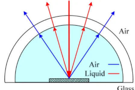
The previous immersion in the diffraction instrument, because of immersion media’s, container’s and air’s interfaces occur twice refraction. So the original diffraction angle is distortion and it’s rather difficult to obtain the more precise angle.
From physical optics and geometric theory, we can know that all of the chord through the center of a circle must be tangent with the vertical circle. So this study will use this simple geometric principle to overcome the interface refraction problem between the media and the container. We can easily obtain immersion diffractive angle using the frame as Figure 2.
Figure 2. Schematic of new frame’s immersion diffraction. As the schematic shown, there is a pre-measured grating setting at in transparent circular container, and the diffraction plane will took place at the circular center of a circle container.
Then we add the liquid medium in the container to fill space full. In order to avoid total internal reflection (TIR) the required liquid and the container material’s reflective index should be similar to realize these experimental ideas mentioned above. After the completion of Setting up, we begin to rotate the devise to make the beam’s incident angle equal to the Littrow diffraction angle. When the angle reaches the Littrow diffraction angle, the diffraction beam will be along the direction of the incident to return, and this angle between the grating normal and the incident beam is that we want for the immersion diffraction angle.
After obtaining the immersion diffraction angle, with the laser light source with known wavelength λ and the grating’s pitch P, the Eq. (3) of the Littrow diffraction configuration can be rewritten as sin 2P m n (4)
where n and m denote the refractive index of immersion liquid and the number of diffraction’s order, respectively.
EXPERIMENT DESIGN AND CONFIGURATION
Laser Diffractometer
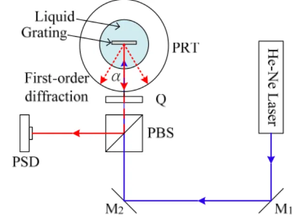
Figure 3. A laser diffractometer assembled on the precision rotating table. In order to establish the laser diffraction technique of the refractive index measurement of liquid, we must first to do calibration of the laser diffractometer and determine the diffraction grating pitch. Experimental architecture (Figure 3) combines a green light He-Ne laser with 543 nm wavelength (1), a high-precision positioning rotary platform (PRT, 5), a four-quadrant position sensitive detector (PSD, 6), four-axis adjustment device (4), and a circular transparent container; the above-mentioned devices will be placed on the vibration isolation platform. The PSD will make signal of spot position output to the industrial computer for processing.
In this study, the composition of optical path are polarization beam splitter (PBS, 2), two mirrors and a quarter phase retard plate (QP, 3) to form an optical measurement system. The He-Ne laser of 543 nm wavelength through the mirrors group and through the polarized beam splitter after, p-polarization of light will penetrate but s-polarization of light
will be reflected to the right side. When the linearly p-polarization light through the quarter phase retard plate, it will become a circularly polarization light, aiming at the sample placed on the four-axis adjustment device. Then rotating the high-precision positioning rotary platform, when it meets the Littrow configuration, the diffraction beam will follow the original optical path back, and through the quarter phase retard plate again, turn into the linearly polarization light and it have a 90 degrees polarized. Then this linearly polarization light will be reflected by PBS to the four-quadrant position sensitive detector. In usually the intensity of diffracted light is not such high, and higher-order diffraction lights is more difficult to detect by PSD’s sensor. But the use of this optical path design, it will be able to effective use of light energy; to avoid diffraction lights generated by the grating cannot be detected by the PSD’s sensor. In the determining grating’s pitch, it must to make precision rotating platform’s degree to zero and adjust the four-quadrant position sensitive detector first, so the center of the detector and the reflecting zero-order diffraction light spot are coincidence. We can use this position as a reference point for the measurement of space. Then we control the computer software to operate the high-precision positioning rotary platform. Input a positive angle, the high-precision positioning rotary platform will clockwise rotate until a first-order diffraction spot and the center of PSD’s sensor coincide. This rotation angle is named
1
. Similarly, counter-clockwise rotation of the platform can find a negative first-order diffraction angle, 1. After taking the average of these two angles, we can obtain
average
.
Substituting it into Eq. (3) can calculate the pitch of this grating.
Figure 4. A diffraction grating immersed in the test liquid.
Refractive Index of Liquid
In order to avoid the concerns of total internal reflection and refractions, we use an idea from geometrical optics combined with the diffraction technique for measuring the refractive index of liquid, as shown in Figure 4. In this study, we use two He-Ne lasers of 543 and 633 nm wavelengths to achieve the refractive index measurements of pure water and several liquid at 20℃.
Here comes an extension structure of the laser diffraction in the previous section, a diffraction grating placed in the center of a circular container so that the diffraction grating plane coincides with the center of a circle. As the container has not yet added the liquid medium, the pitch
measured in the air at the this time will be the standard value in the following experiments; after measuring the standard value of pitch, then add the liquid into the container, we can start measuring the diffraction angle of different liquids.
Because of the incident laser beam will be reflected to the quarter phase retard plate by the polarization beam splitter, so that the linear polarized light will change into circular polarized light, then circular polarized light through the container without refractive effect and be arrival the grating soaked in the medium. We use the adjusted four-quadrant position sensor and set the center of photo sensitive elements for a reference zero point and then rotate the positioning rotary platform. Based on the Littrow configuration, we can find a diffraction beam along the original path returns through the positive and negative first-order diffraction light, respectively. We adjust the diffraction spot to the PSD center by rotating PRT slowly, and then read the angle of rotating platform, we can obtain the angle between the positive and negative first order diffraction beams, as 2 . Finally, the above measured diffraction angles and the standard pitch of the grating are substituted into the Littrow diffraction formula, Eq. (4). Accordingly, the refractive index of the liquid is calculated.
Figure 5. Schematic of the laser diffractive refractometer.
Pitch’s Measurements and Samples’ selection
The immersion laser diffraction technique infiltrated of the above chapter, it serves to confirm its feasibility after the experiment. In the first part of this chapter, we will choose several transparent clear liquid as the measurement samples. The experimental results are also performed with reference values. By changing the different liquid which obtained different solute and measuring experimental data, we can explain the relationship between composition and refractive index changes of the solutions. Before the index’s measurement, we need to measure the diffraction grating pitch which will be used of laser diffraction. We use a one-dimensional grating manufacture by Edmund Optics. The refractive index of air in environment is 1.000271, and we use high-precision rotary platform to measure diffraction angles of the grating as shown in Figure 3. Since the measured result of first order diffraction angle is 19.01421 degree, Eq. (4.1) yields the pitch value of 833.890 nm.
EXPERIMENT RESULTS
This section uses laser diffraction to measure the liquid refractive index which immersed the diffraction grating. Edmund Optics’ one-dimensional grating is used, with the grating pitch 833.890 nm measured in the last section. Commonly the high-precision rotary platform is used to measure displacement of diffraction angles. With the measured diffraction angles and calculation of Eq. (4), the refractive index of immersion liquid, n, can be obtained.
Refractive index of transparent solution
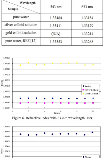
We use laser diffraction and operate high-precision rotary platform in order to measure the diffraction angle; through calculating Eq. (4) with the measured diffraction angle, we can obtain the refractive index of immersion liquids, n. The Experimental samples of transparent liquid are pure water, 40 nm colloid silver solution and 40 nm colloid gold solution. After some equation calculations, the averages of refractive index in the 633 nm wavelength light are 1.33184, 1.33179 and 1.33214, respectively. The distribution of refractive index data is shown in Figure 6.
We use the light source with 543 nm wavelength light. The refractive index of pure water and 40 nm colloid silver solution are 1.33484 and 1.33411, respectively. The data distribution is shown in Figure 7. Additionally, the 40 nm colloid gold solution’s diffraction lights will be absorbed in the use of 543 nm wavelength light. So we cannot produce the diffraction angle in this case.
Refractive index of translucent solution
We also use the laser diffraction method and a similar principle to measure the refractive index of translucent liquids. The experimental samples are solutions of polystyrene particles in nanometer scale; the particle’s diameters are 100, 300, 500 and 900 nm. After calculating with diffraction angles, the average of refractive index in 633 nm wavelength light source is about 1.33467 and the data distribution is shown in Figure 8.
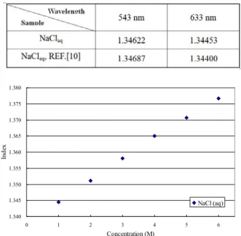
Dealing with four kinds of nanoparticle solution subjected to 543 nm wavelength light, the average refractive index of 100, 300, 500 and 900 nm nanoparticle solution are 1.33154 and the data distribution is shown in Figure 9. Then we change the sample to the clearly transparent solution of NaCl. The concentrations of the molar concentration are from 1 to 6M, for which there are six samples. Through experiments and calculations, the refractive index of the NaCl solution in the 633 nm wavelength light, the data distribution of each concentration of the sample are shown in Figure 10.
REFRACTIVE INDEX OF TRANSPARENT SOLUTIONS IN 20˚C
1.33175 1.33180 1.33185 1.33190 1.33195 1.33200 1.33205 1.33210 1.33215 1.33220 0 2 4 Times6 8 10 Inde x Water Sliver Colloid Gold Colloid
Figure 6. Refractive index with 633nm wavelength laser
1.33400 1.33410 1.33420 1.33430 1.33440 1.33450 1.33460 1.33470 1.33480 1.33490 1.33500 0 2 4 6 8 10 Times In de x Water Sliver Colloid
Figure 7. Refractive index with 543nm wavelength laser
1.3325 1.3330 1.3335 1.3340 1.3345 1.3350 1.3355 0 2 4 6 8 10 12 14 16 Times Inde x 100 nm 300 nm 500 nm 900 nm AVG. 1.33467
Figure 8. Refractive index of particle solution with 543nm wavelength laser
1.3295 1.3300 1.3305 1.3310 1.3315 1.3320 1.3325 0 2 4 6 8 10 12 14 16 Times Inde x 100 nm 300 nm 500 nm 900 nm AVG. 1.33154
Figure 9. Refractive index of particle solution with 633nm wavelength laser
REFRACTIVE INDEX OF NACL SOLUTIONS (1M) BY TWO WAVELENGTHS
1.340 1.345 1.350 1.355 1.360 1.365 1.370 1.375 1.380 0 1 2 3 4 5 6 Concentration (M) In de x NaCl (aq)
Figure 10. Refractive index of NaCl solution with 543nm wavelength light source
CONCLUSION
This study used a horizontal rotary platform with superior angular resolution and automatic measurement to avoid the
defect of vertical rotary platforms. The application of laser diffractometers is extensive, and measuring the refractive index of liquid is effective and accurate by using LD. Unlike other refractometers of interferometry and critical angle, this measurement principle is based on the Littrow configuration, in which a reflective diffraction beam coincides with an incident beam. The use of optical components is uncomplicated and substitution of measurement equation is simple. The measurement repeatability is higher than other systems. This study has presented the diffraction angle detection and diffractometry for measuring the refractive index of liquids.
As depicted in Tables 1 and 2, there are eight kinds of liquids. In experiments, lasers of different wavelengths shoot in those liquids. Refractive indices of transparent solutions will change between 0.0007 and 0.0008. By contrast, refractive indices of translucent solutions remain the same as that of pure water.
REFERENCES
J. R. Castrejón-Pita, A. Morales and R. Castrejón-García, “Critical angle laser refractometer”, Rev. Sci. Instrum., Vol. 77, 2006.
C. J. Chen, S. P. Pan, L. C. Chang and G. S. Peng, “Pitch calibration by reflective laser diffraction”, Proc. of SPIE, Vol. 5190, pp. 156-164, 2003.
G. Dai, “Accurate and traceable calibration of one-dimensional gratings”, Meas. Sci. Technol., Vol. 16, pp. 1241-1249, 2005.
V. I. Korotkov, S. A. Pulkin, A. L. Vitushkin and L. F. Vitushkin, “Laser interferometric diffractometry for measurements of diffraction grating spacing”, Applied Optics, Vol. 35, pp. 4782-4786, 1996.
S. H. Lu, “Immersion diffractometry for determining nanoscale grating pitch”, Optics Express, Vol. 14, pp. 9564-9569, 2006.
S. H. Lu, S. P. Pan, T. S. Liu, and C. F. Liu, “Liquid refractometer based on immersion diffractometry”, Optics Express, Vol. 15, pp. 9470-9475, 2007.
J. Meaburn, “Detection and spectrometry of Faint Light”, Reidel, Dordrecht, 1976.
F. Meli, R. Thalmann and P. Blattner, “High precision pitch calibration of gratings using laser diffractometry”, Proc. of the 1st Int. Conf. on Precision Engineering and Nanotechnology, Vol. 2, pp. 252-255, 1999. E. Moreels, C. de Greef, and R. Finsy, “Laser light refractometer”, Applied
Optics, Vol. 23, pp. 3010-3013, 1984.
N. E. Dorsey, "Properties of ordinary water-substance", Hafner Publishing Company, 1940.
Y. Sarov, S. Sainov, and I. Kostic, “Automatic VIS-near IR laser refractometer”, Rev. Sci. Instrum., Vol. 75, pp. 3342–3344, 2004. P. Schiebener, J. Straub, J. M. H. Levelt Sengers, and J. S. Gallagher,
"Refractive index of water and steam as function of wavelength, temperature and density," J. Phys. Chem. Ref. Data, Vol. 19, No. 3, pp. 677-717, 1990.
T. Wei, Y. Han, Y. Li, H.L. Tsai and H. Xiao, “Temperature-insensitive miniaturized fiber inline Fabry-Perot interferometer for highly sensitive refractive index measurement,” Opt. Express, Vol. 16, pp. 5764–5769, 2008.