國
立
交
通
大
學
資訊學院 資訊學程
碩
士
論
文
在 VoIP 環境中的彈性化監聽方案
Flexible Interception in VoIP Environment
研 究 生:顏士哲
指導教授:蔡文能 教授
在 VoIP 環境中的彈性化監聽方案
Flexible Interception in VoIP Environment
研 究 生:顏士哲 Student:Shih-Che Yen
指導教授:蔡文能教授 Advisor:Dr. Wen-Nung Tsai
國 立 交 通 大 學
資訊學院 資訊學程
碩 士 論 文
A Thesis
Submitted to College of Computer Science National Chiao Tung University in partial Fulfillment of the Requirements
for the Degree of Master of Science
in
Computer Science May 2008
Hsinchu, Taiwan, Republic of China
在 VoIP 環境中的彈性化監聽方案
學生:顏士哲
指導教授
:蔡文能教授
國 立 交 通 大 學
資 訊 學 院 資 訊 學 程 碩 士 班
摘
要
由於
IP 網路的蓬勃發展,再加上更便宜的通訊費用和更多樣化的加值服
務,
VoIP 的技術成為傳統 PSTN 網路的替代方案。但是在提供通訊服務之外,
電信業者也必須提供合法的監聽管道,提供政府能夠執行合法的監聽。本篇
論文在現行的網路基礎架構下,提供彈性化的
VoIP 監聽方案。我們提供了
一套名為
FIVE System 的彈性化監聽方案,提供五種不同的監聽模式,並針
對不同的模式做評估與分析。
我們提供的五種監聽方式分別為:The Rogue Back to Back Interception,
The Rogue SIP Proxy Interception, The SIP Proxy attached Interception, Remote
Attack Interception and Port Mirroring Interception。每一種不同的監聽模式都
可應用在某一種網路區域,而且各有其優點。藉由我們
FIVE System 的協助
下,政府單位可以選擇最適合的方式來做合法的監聽。我們也建構了
VoIP
的環境來驗證我們的
FIVE System,所得到的實驗結果更可以提供未來使用
FIVE System 的參考。而各種彈性化的方案,提供使用者根據不同的網路類
型選擇方案,或者使用混合的方式得到最佳的網路監聽效果。
Flexible Interception in VoIP Environment
student:Shih-Che Yen
Advisors:Dr.Wen-Nung Tasi
Degree Program of Computer Science
National Chiao Tung University
ABSTRACT
The VoIP is growing rapidly due to the popular of the Internet network. The
VoIP can provide the cheaper communication fee and various values-add
services. It can replace the traditional PSTN network. But the VoIP network
should also provide the lawful interception function for government. This thesis
based on the current network architecture to provide a Flexible Interception in
VoIP Environment. We name this system as FIVE system.
The FIVE system is a flexible interception system. It provides five different
interception models for interception. The five models are Rogue Back to Back
Interception, Rogue SIP Proxy Interception, SIP Proxy attached Interception,
Remote Attack Interception, and Port Mirroring Interception. All interception
models have their advantages. The government can do the flexible interception
by using the FIVE system. We also setup the VoIP environment to do the
experiment according to our experimental results. Government can choose the
best solution to adapt the different network environment. And the hybrid mode
誌
謝
在交大求學的這段期間很感謝各位師長的諄諄教誨,和各位同學的相
互勉勵之下,讓我可以順利的完成課業,和論文的相關研究。首先要感謝
蔡文能教授擔任我們的指導教授,對於我們的論文研究和專業知識都不辭
辛勞的給予許多的指導和協助。在論文研究的學習過程中,我們不但得到
了許多專業的知識,並且學習到了做學問的方法。再來是感謝和我一起努
力的同學們,雖然大家都是以在職的身份同時忙於工作和課業,但是在我
們的相互激勵和幫助之下,我們在課業方便都得到了不錯的結果。最後是
感謝我的內人李佳倩小姐。在這兩年的求學過程中,總是辛勤的幫我扶持
家務,讓我能沒有後顧之憂的努力於事業與課業之上。也感謝交大能提供
這樣的環境和機會,讓我在出社會之後仍有進修的機會。今天我以身為交
大人為榮,希望他日交大也會以我為榮。
Contents
中文摘要
... i
英文摘要
...ii
誌謝
...iii
Contents... iv
FIGURE Contents ... vi
TABLE Contents...viii
Chapter 1 Introduction ... 1
1.1 Motivation... 1
1.2 Object ... 2
1.3 Emphasis ... 2
1.4 “FIVE” System Introduction... 3
Chapter 2 Background... 4
2.1 Overview of VoIP ... 4
2.2 VoIP Architecture... 5
2.3 VoIP Protocols ... 6
2.3.1 SIP ... 6
2.3.2 MGCP... 7
2.3.3 MEGACO... 7
2.3.4 H.323 ... 7
2.3.5 RTP... 7
2.3.5 RTCP ... 8
2.4 SIP standard call flow ... 8
Chapter 3 Related Work... 11
3.1 VoIP Security ... 11
3.1.1 VoIP Security Analysis ... 11
3.1.2 VoIP Security Issues ... 14
3.2 VoIP Interception ... 16
3.2.1 VoIP Interception Model... 16
3.2.2 The VOIP Interception solutions of each vendor... 20
Chapter 4 The FIVE System ... 22
4.1 System Overview ... 22
4.1.1 The System Architecture ... 23
4.1.2 The Programming Environment... 24
4.1.3 The Windows Packet Capture Library ... 25
4.2 FIVE System Interception Mechanisms... 28
4.2.3 The SIP Proxy Attached Interception... 35
4.2.4 The Remote Attack Interception ... 40
4.2.5 The Port Mirroring Interception... 44
Chapter 5 Experimental Result ... 47
5.1 Experimental Environment ... 47
5.1.1 SIP Proxy – OnDO SIP Server... 48
5.1.2 IAD – X-Light ... 49
5.1.3 Interception Server – FIVE System ... 50
5.2 Experimental Result ... 50
5.2.1 FIVE System performance measurement criteria ... 51
5.2.2 FIVE System performance measurement benchmark... 52
5.3 Experimental Results... 53
5.3.1 The Average Delay in FIVE system ... 53
5.3.2 The Jitter in FIVE system... 54
5.3.3 The Stability of FIVE system... 55
5.4 The Problems of the FIVE System... 56
Chapter 6 Conclusion and Future Works... 58
6.1 Conclusion... 58
6.2 Future Works... 60
Reference ………62
FIGURE CONTENTS
F
IGURE1.
A
S
IMPLEV
OIP
N
ETWORK... 5
F
IGURE2.
V
OIP
NETWORK WITHPSTN
NETWORK... 6
F
IGURE3.
SIP
V
OIP
NETWORK TOPOLOGY... 9
F
IGURE4.
SIP
CALL FLOW... 10
F
IGURE5.
T
HEV
OIP
ATTACK SPOOFED“B
YE”
FLOW... 14
F
IGURE6.
T
HERTP
C
ONTENT... 15
F
IGURE7.
T
HESRTP
C
ONTENT... 15
F
IGURE8.
D
ISTRIBUTEDS
YSTEM FORL
AWFULI
NTERCEPTIOND
IAGRAM... 17
F
IGURE9.
T
HE CENTRALMSM
SYSTEM... 18
F
IGURE10.
T
HE DISTRIBUTEDMSM
SYSTEM... 18
F
IGURE11.
T
HESIP
P
ROXYA
TTACHEDI
NTERCEPTION... 19
F
IGURE12.
T
HER
OUGEB
ACK TOB
ACKU
SERA
GENTI
NTERCEPTION... 20
F
IGURE13.
T
HER
OGUESIP
P
ROXYI
NTERCEPTION... 20
F
IGURE14.
F
IVES
YSTEMI
NTERCEPTIONP
OINTS... 22
F
IGURE15.
S
YSTEMB
LOCKD
IAGRAM... 23
F
IGURE16.
T
HEM
ICROSOFTV
ISUALC++
E
NVIRONMENT... 24
F
IGURE17.
T
HEW
INS
OCK2
ANDW
INPCAP
ARCHITECTURE... 25
F
IGURE18.
W
IRESHARKP
ACKETC
APTUREW
INDOW... 26
F
IGURE19.
FIVE
S
YSTEMP
ACKETP
ROCESSINGM
ECHANISM DIAGRAM... 27
F
IGURE20.
FIVE
S
YSTEMP
ACKETR
ESTOREM
ECHANISM... 27
F
IGURE21.
T
HER
OGUEB2BUA
S
ERVERM
ODEL... 28
F
IGURE22.
T
HER
OGUEB2BUA
S
ERVERI
NCOMINGC
ALLI
NTERCEPTION FLOW29
F
IGURE23.
T
HER
OGUEB2BUA
S
ERVERO
UTGOINGC
ALLI
NTERCEPTION FLOW29
F
IGURE24.
T
HER
OGUEB2BUA
S
ERVERR
EGISTER FLOW... 30
F
IGURE25.
T
HER
OGUEB2BUA
S
ERVERSDP
EXCHANGE FLOW... 30
F
IGURE26.
T
HER
OGUEB2BUA
S
ERVERI
NTERCEPTIONRTP
FLOW... 31
F
IGURE27.
T
HER
OGUEB2BUA
S
ERVERI
NTERCEPTIONS
TATEM
ACHINE... 31
F
IGURE28.
T
HER
OGUESIP
S
ERVERM
ODEL... 32
F
IGURE29.
T
HER
OGUESIP
S
ERVERI
NCOMINGC
ALLI
NTERCEPTION FLOW... 33
F
IGURE30.
T
HER
OGUESIP
S
ERVERO
UTGOINGC
ALLI
NTERCEPTION FLOW... 33
F
IGURE31.
T
HER
OGUESIP
S
ERVERSDP
EXCHANGE FLOW... 34
F
IGURE32.
T
HER
OGUESIP
S
ERVERO
UTGOINGC
ALLI
NTERCEPTION FLOW... 34
F
IGURE33.
T
HER
OGUESIP
S
ERVERS
TATEM
ACHINE... 35
F
IGURE34.
SIP
P
ROXYA
TTACHEDM
ODEL... 36
F
IGURE35.
T
HESIP
P
ROXYA
TTACHEDO
UTGOINGC
ALLI
NTERCEPTION FLOW.. 36
F
IGURE38.
T
HESIP
P
ROXYA
TTACHEDSDP
EXCHANGE FLOW... 38
F
IGURE39.
T
HESIP
P
ROXYA
TTACHEDI
NTERCEPTIONS
TATEM
ACHINE... 39
F
IGURE40.
T
HER
EMOTEA
TTACKM
ODEL... 40
F
IGURE41.
ARP
TABLE BEFOREARP
SPOOF ATTACK... 41
F
IGURE42.
T
HEARP
SPOOF ATTACK LOG... 41
F
IGURE43.
ARP
TABLE AFTERARP
SPOOF ATTACK... 41
F
IGURE44.
SIP
R
EGISTERR
EQUEST... 42
F
IGURE45.
T
HER
EMOTEA
TTACKO
UTGOINGC
ALLI
NTERCEPTION FLOW... 43
F
IGURE46.
T
HER
EMOTEA
TTACKI
NCOMINGC
ALLI
NTERCEPTION FLOW... 43
F
IGURE47.
R
EMOTEA
TTACKS
TATEM
ACHINE... 44
F
IGURE48.
ARP
POISONING ATTACK... 45
F
IGURE49.
S
WITCHP
ORTM
IRRORING... 45
F
IGURE50.
W
IRESHARKV
OIP
C
ALLG
RAPHA
NALYSIS... 46
F
IGURE51.
T
ESTINGE
NVIRONMENTD
IAGRAM... 47
F
IGURE52.
O
ND
OSIP
S
ERVERR
EGISTEREDL
IST... 49
F
IGURE53.
X-L
ITEGUI
AND CONFIGURE MENU... 49
F
IGURE54.
FIVE
S
YSTEMGUI... 50
F
IGURE55.
RTCP
R
ECEIVER’
SR
EPORT... 51
F
IGURE56.
T
HEJ
ITTER VARIATION DURING A NORMAL CALL... 52
F
IGURE57.
FIVE
S
YSTEMA
VERAGED
ELAY... 53
F
IGURE58.
FIVE
S
YSTEMA
VERAGEJ
ITTER... 54
F
IGURE59.
FIVE
S
YSTEMJ
ITTERO
VERHEAD... 55
TABLE CONTENTS
T
ABLE1.
SIP
R
EQUESTC
OMMANDS... 8
T
ABLE2.
SIP
R
ESPONSEC
OMMANDS... 9
T
ABLE3.
T
HEV
OIP
V
ULNERABILITIESC
LASSIFICATION... 12
T
ABLE4.
C
ONFIDENTIALITYV
OIP
VULNERABILITIES MATRIX... 12
T
ABLE5.
I
NTEGRITYV
OIP
VULNERABILITIES MATRIX... 12
T
ABLE6.
A
VAILABILITYV
OIP
VULNERABILITIES MATRIX... 13
T
ABLE7.
V
OIP
S
ECURITYT
HREATS... 13
T
ABLE8.
T
HEVOIP
INTERCEPTION SOLUTIONS OF EACH VENDOR... 21
Chapter 1 Introduction
Traditional PSTN (Public Switched Telephone Network) telecommunication service provides stable services for years. It can reach the five nines service quality. But circuit switching network always costs a lot in the network architecture construction. It is hard to do the cost down. But by the arising of the Internet network, we have chances to choose VoIP (Voice over Internet Protocol) to make a phone call. And VoIP can support more value added services. Video call is one of the new features. That will bring us to a more modern life style.
The VoIP is used to transport the voice by using the Internet Protocol. For the growing volume of the Internet users, and the complete Internet Network construction, the trend will push us to next generation communication network. The NGN (Next Generation Network) is going to replace the current PSTN network. It will provide us a cheaper charge of the
communication fee, as well as much add-value services. But before this technique being matured, there are still many security concerns.
1.1 Motivation
After working in a telecomm company for years, we understand to provide a total solution is very important. The best advantage of the VoIP is that the technique is based on the widely used IP network. The service provider didn’t need to construct their own network infrastructure. But it also brings up many the security issues. And to modify the current infrastructure to a complete new one will be impossible. The cost will be incredible.
So there will be two major reasons that we choose this topic. The first reason is that the VoIP network security is very important. If we didn’t secure the security, it will lead to more problems, such as quality, privacy even the crime. For example, if someone uses the credit card by phone, the credit card pin number might be stolen by the voice interception. These issues will lead to serious crime problems. The security issues in VoIP are not only the IP protocol layer problems. But also the VoIP protocols, the applications and the Operation
System flaws. The internet is an open space for everyone to access, so all of the security issues should be concerned. We can review the security issue by the concept of OSI network models; it could be some flaws in each layer. The protection should be well concerned in any aspect of it.
And another reason is the government always requests the telecomm service provider to provide a lawful interception function for the government. But this is another big problem for the service providers. We know that the packet switching network always didn’t have a fix routing path and you can’t easily wiretap your target machine. Even the soft switch only management the signaling messages. So if you can’t wiretap your target in LAN, you should wiretap the specific equipment or to do the interception in some specific access points. Our study will provide a solution of it.
1.2 Object
Due to the cost of reconstruct the IP network infrastructure will be incredible. So we’ll base on the original infrastructure to provide a software based solution to do the interception. The application should be individual, and running in an individual sever or attach in a server without modify or recompile the VoIP protocol stack in the server.
First of all, we will introduce all of the VoIP security vulnerabilities in different points of view, and then to study how to attack the VoIP network countermeasures. Based on the studies, we will implement a VoIP network program that can support varies lawful interception models. And build a test environment to verify our solution.
1.3 Emphasis
There are two emphases in this thesis. The first one is the analysis of the VoIP security issues. And the one second is the VoIP interception system.
The current VoIP protocol is based on the IP network, so it inherits all of the problems in the IP network. Unsecured VoIP network may bring up many serious problems. The users
might be stolen. So the security issues are a major part that we want to study.
The second part is the lawful VoIP interception. For the security issue, the government needs to intercept the specific people or phone. But the call routing in VoIP is not the same as traditional PSTN phone, so we need a new solution for the VoIP interception. It is better to keep the current VoIP architecture. So we’ll provide a software based solution to achieve this goal.
1.4 “FIVE” System Introduction
We build a software based system to do the interception, and we name this system “FIVE” system. This name has two meanings; the first is the “Flexible Interception in VoIP Environment”. It is the target of the system. Another reason is our system provides 5 different interception models. The interception server has different locating in these five different in the VoIP network. And use different mechanisms to process the interception. We will descript the details about how to implement them, and also do the compare and analysis the result of experiment.
Chapter 2 Background
The VoIP signaling and voice packet will be transport in the Internet. So the Internet protocol is the basic of the VoIP protocols, and there are still other protocols and equipments to construct the VoIP environment. In this chapter, we will introduce all of the background knowledge of VoIP.
The first is the overview of VoIP network. We’ll introduce the architecture of the VoIP network. And then is the VoIP related protocols, there are various VoIP related protocols that support different functions. Most important of all, the signaling protocols is what we need to take care. The call setup procedure is defined in the signaling protocols. So we’ll also
introduce a standard call setup flow of SIP, because we need the standard flow for our, and to compare with the modifications.
2.1 Overview of VoIP
VoIP is a packet switching telecommunication technique, different from the traditional PSTN circuit switching network. The analog voice signal will be convert into digital datagram. And the packet will be transported by the IP network. And the receiver side will receive the data packet and roll back to the analog voice. The routing of the packet will depends on the router’s decision, the voice packet maybe not arrive in order. The VoIP will need some mechanism to deal with these issues. Traditional PSTN will create a lease-line for one call, will cost more than VoIP. But the quality is stable and good.
The packet switching technique will bring up the reliability issues. Besides the low cost and many value-added services, the VoIP also bring up many problems. The unreliability transmission may lead to jitter, packet loss and delay. The NAT (Network Address Transfer) and emergency call will also be the problems that the service providers have to handle. So the quality and security are both very important.
2.2 VoIP Architecture
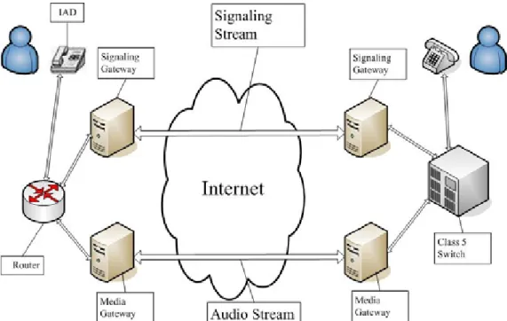
The traditional telephony network is PSTN (Public Switched Telephone Network) network. When someone makes a phone call will reserve a lease line for the communication. But circuit switching is costly, the VoIP provide a packet switching solution based on the current IP network. A call will be divided into two streams, one is the signaling stream for transmit the call setup command. And another one is the audio stream for the voice packet. The streams didn’t have the fix routing rules, so the packet will follow the normal IP network routing rule to the destination. The following figure is a simple VoIP network example. The signaling stream will carry the signaling protocols such as SIP, MGCP, MEGACO and H.323. And the audio stream will carry the voice data by Real-time Transport Protocol.
Figure 1. A Simple VoIP Network
The VoIP network can also connect to the current PSTN network. We just need a Signaling Gateway to convert the call processing signal into the SS7 signal. And also need a Media Gateway to convert the audio stream into the analog data, and send it to a Class 5 switch, and then new VoIP network and old PSTN network can connect together.
Figure 2. VoIP network with PSTN network
2.3 VoIP Protocols
The VoIP protocols support the functions of call setup, control message delivery, and resource allocation. So we’ll introduce the various important VoIP protocols in the VoIP and their functions. All of them are the important elements to construct the VoIP network, and we have to familiar with these protocols.
2.3.1 SIP
The SIP (Session Initiation Protocol) is a VoIP signaling protocol. Designed for create Internet sessions for audio or multimedia data transmission. It was developed by Columbia University and University College London, and the latest version defines in the RFC 3261 from the IETF SIP working group. SIP controls the call setup progress in the VoIP; it can setup or tear down a call by SIP signaling, or even create a conference call party. SIP is a peer-to-peer protocol, different from MGCP and MEGACO. In VoIP, SIP works as a carrier of SDP to create the RTP stream to do the communication.
2.3.2 MGCP
MGCP (Media Gateway Control Protocol) is a signaling protocol within a VoIP system. The detailed definition of MGCP is defined in RFC 3435. And still many other RFC to describe the other details of MGCP. In MGCP architecture, there will be one Media Gateway to convert the audio to data packet, and a Signaling Gateway to create the connection of two end points. And the Call Agents is handled by the Media Gateway. MGCP messages are a series of commands that handles the call processing.
2.3.3 MEGACO
The MEGACO (Media Gateway Control Protocol) or H.248 protocol is also a VoIP signaling control protocol. The protocol was developed by both IETF and ITU, so the details of this protocol are defined in RFC 3525 of IETF and H.248-1 of ITU-T. The protocol provides the ability for the Media Gateway Controller to control the gateway to process the call processing. It contains the concept of context, and the command format is quite different from SIP and MGCP.
2.3.4 H.323
H.323 is created by the ITU-T for the multimedia transmission in LAN. And it is the first VoIP standard to serve the VoIP call processing. H.323 is not only used in VoIP, but also the IP based video conference, such as the NetMeeting. The H.323 call processing is defined in the ITU-T Q.931, and similar to the standard ISDN call setup. We will need to setup a H.323 Gatekeeper if we want to run the H.323 protocol in the VoIP network.
2.3.5 RTP
RTP (Real-time Transport Protocol) is a network transport protocol, developed by the Audio-Video Transport Working Group of IETF. RTP defines a standard datagram format of the audio and video. The RTP didn’t define the specific port for the transmission, and can support both unicast and multicast transmission. Using RTP in VoIP is as a unicast streaming
media transmission.
2.3.5 RTCP
RTCP (Real-time Transport Control Protocol) defines in RFC 3550. RTCP provides the out of band control of RTP media stream, but with no media payload on it. The main function of the RTCP is to provide the QoS (Quality of Service) information of the RTP stream. Such as the transmitted octets, received octets, packet loss, jitter. The RTCP packet will be
periodically send out for the terminal to measure the quality of the conversation.
2.4 SIP standard call flow
We were taking SIP as a sample signaling protocol to discuss how to implement the VoIP interception. We’ll introduce the SIP call processing flow in this section. The following tables are the descriptions of the SIP request commands. The command sequence will
establish the call setup procedure.
SIP Request Command Command Description INVITE To initial a call
BYE To terminate a call
ACK The acknowledge of a command
OPTIONS Query some information
CANCEL To cancel a request
REGISTER To register location information Table 1. SIP Request Commands
The response commands always carry an integer to indicate the status of the result. The following table is the roughly definitions of the different numbers. For example, the 100 is trying, 180 is ringing. 200 is means ok, and 202 is accepted.
SIP Response Command Command Description 100 ~ 199 Information 200 ~ 299 OK 300 ~ 399 Redirection 400 ~ 499 Client Error 500 ~ 599 Server Error 600 ~ 699 Global Error
Table 2. SIP Response Commands
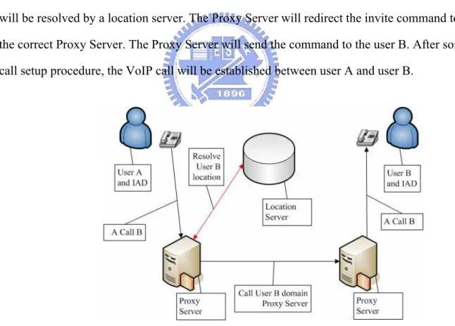
The following diagram is an example of a sample SIP call. User A wants to call User B. The call setup command will send to the proxy sever to process. And the location of user B will be resolved by a location server. The Proxy Server will redirect the invite command to the correct Proxy Server. The Proxy Server will send the command to the user B. After some call setup procedure, the VoIP call will be established between user A and user B.
Figure 3. SIP VoIP network topology
The following diagram is a standard call setup flow of the SIP call, the black flow is the call setup from the user A, the red flow is the call terminate from user A. After the user A off hook the phone and dial a number. The IAD sends the invite command to the SIP Proxy. SIP
Proxy will try to route the message to the correct SIP Proxy, and transmit the invite command to the user B. When the user B answers this call, the IAD will send the OK acknowledgement back to the caller. After some call setup process, a RTP stream will be create to transmit the voice data between the users.
Chapter3 Related Work
There are various VoIP study publications that focus on different points of view. We have to reference these studies to get the necessary information to attack the VoIP
vulnerabilities. There are a lot VoIP vulnerability studies for us to reference. We’ll use the vulnerabilities to do the interception in this thesis especially in the remote attack interception model. About the VoIP interception related studies also provide us many ideas about how to design a better mechanism to do the VoIP interception. And our target is to provide a better solution.
3.1 VoIP Security
The VoIP have various security issues. And also many studies in this domain. Within the different motivation and different target, they have different points of views in this subject. Some of them will analysis the issues, and some of them will discuss how to avoid them. The following is the keys of the related studies that we have referenced.
3.1.1 VoIP Security Analysis
To analysis the VoIP security issues, we can divide the issues into different classification to discuss. In “An Analysis of Security Threats and Tools in SIP-Based VoIP Systems [1]” the authors provided a VoIP security matrix for our reference. All of the issues can be filled into the matrix. The issues could be happened in the Network Interface Layer, Network Layer, Transport Layer or Application Layer. And the vulnerabilities will affect three major areas as the following table. This thesis provides us an idea to classify our interception mechanism. Our interception mechanism will break the confidentiality by the vulnerabilities of different network layers. The following table is the VoIP vulnerabilities classification. Our study will break the confidentiality and integrity and to do the interception.
Vulnerabilities affect area Description
Confidentiality The information could not be reachable by illegal user Integrity The information could not be modified
Availability The service could not be disturbed Table 3. The VoIP Vulnerabilities Classification
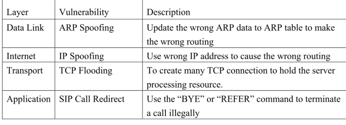
The vulnerabilities affect four layers of the TCP/IP networking model. They are Network Interface Layer, Network Layer, Transport Layer and Application Layer. There are a lot of vulnerabilities in each layer. And the following tables are the sample VoIP vulnerabilities matrix in the paper:
Layer Vulnerability Description
Data Link MAC Spoofing Media Access Control (MAC) address spoof to impersonating the devices
Internet IP Spoofing IP address spoof to impersonating devices Transport TCP Interception To sniff the TCP packet
Application SIP Call Hijacking To hijack a SIP call for the voice data Table 4. Confidentiality VoIP vulnerabilities matrix
Layer Vulnerability Description
Data Link ARP Spoofing ARP spoofing will corrupt the ARP data
Internet IP Spoofing Integrity can be compromised at the network layer by an IP address spoof
Transport TCP Interception To sniff the TCP packet and to modify it Application RTP Inserting To insert the Voice data to the RTP stream
Layer Vulnerability Description
Data Link ARP Spoofing Update the wrong ARP data to ARP table to make the wrong routing
Internet IP Spoofing Use wrong IP address to cause the wrong routing Transport TCP Flooding To create many TCP connection to hold the server
processing resource.
Application SIP Call Redirect Use the “BYE” or “REFER” command to terminate a call illegally
Table 6. Availability VoIP vulnerabilities matrix
“Vulnerability Analysis and Best Practices for Adopting IP Telephony in Critical Infrastructure Sectors [2]” describes the security issues. Also provide us many useful
recommendations for construct the VoIP network. Critical Infrastructure is a term that used by governments. It describes the essential for the functioning of a society and economy. And Critical Infrastructure includes food, water, telecommunication, energy, and transportation. The following table is the summary of threats:
Threats Description
Protocol Attacks Most of the VoIP have their own vulnerabilities.
Application Attacks Java applets might be running on IP phones for supplementary services. Could be hacked.
OS Vulnerability The overflow might create a backdoor for the hacker to gain full control.
Spoofing on Different Layers
Spoofing can occur on different layers, the complicate identity will increase loading.
Unauthorized Component or User Introduction
Authorization determines what actions can be undertaken with various users.
Unauthorized Access to System Data
The system data, such as configuration files and
administrative data should be protected from attackers. Eavesdropping and
Sniffing on Conversations
VoIP can open the doors for eavesdropping or sniffing on both signaling and voice.
Man-in-the-Middle The rogue proxy could collect the confidential information. DoS (Denial of Service) DoS attack to a proxy server could lead to loss the availability
of service.
Theft of Service The ability to make VoIP calls for nefarious purpose. Table 7. VoIP Security Threats
And all of the vulnerabilities could be address to six security measures. They are Identification and Authentication, Authorization, Confidentiality and Integrity, Access Control, Availability and Security Management. The recommendations remind us the VoIP service providers have to create a secured network, and also care about the compatibility and scalability. In our thesis we will use the Protocol Attacks, Application Attacks and Spoofing on Different Layers to do the interception.
3.1.2 VoIP Security Issues
The signaling protocol is also unsafe in VoIP network. We use SIP as the target signaling protocol in this thesis. A simple spoofed BYE command can easily terminate a call illegally. “A new authentication Mechanism and Key agreement protocol for Sip Using [3]” proposes an identity based cryptography to solve the authentication and key agreement issue in SIP. The Cisco also have the white paper “Security in SIP Based Network [4]” to suggest the user to secure their VoIP network.
The authentication, IPSec and firewall are your countermeasures. “Convert channel for improving VoIP security [5]” provide you a solution to hide the information in your packet in VoIP network. All of these studies are discuss about the SIP protocol securities. We’ll also attack the SIP protocol using spoofed SIP redirect command or some other SIP protocol attacks referenced to these studies.
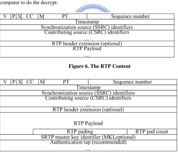
RTP is an application level protocol to carry audio or video data. In “Real-time Transport Protocol (RTP) Security [6]” discussed the RTP serious confidentiality, integrity and authentication issues. But all of the security features must concern about the performance issue. The complex mechanism may bring up the unacceptable delay and jitter, also serious damage the voice quality. “Study on SRTP and Design Key Exchange for Secure VoIP [7]” discussed how to protect your privacy by Secured RTP. Also provide the measurement the latency of SRTP mechanism. We have been challenged that all of the interception will be useless if the end user uses the SRTP to do protection. Cryptography is not the target of our study. We’ll focus on the interception in the aspects of protocols, networks and telecomm. We do not talk about the cryptography. Our target is to collection the conversation data in the RTP flow. And if the recorded payload is encrypted, government can to use the super computer to do the decrypt.
Figure 6. The RTP Content
“VoIP security in Small Business [8]” reviews several kinds of the VoIP security issues. Not only the vulnerabilities had we discussed before. The infrastructure could be the root cause of the risks. When your data package is traveling through the Internet, it is exposed itself to be an attackable target. The end user will also be the target of denial of service, flooding, eavesdropping and impersonation. The hacker might takeover the control of your computer by the operation system overflow bug. Human vulnerabilities are also a problem. Easy to use and security always be a trade off, and most of the network management engineer will choose the easy one. And we would like to provide a software based VoIP interception without changing the infrastructure. So this thesis provides us the information of
infrastructure and management vulnerabilities to do the interception.
3.2 VoIP Interception
A flexible and powerful software based VoIP interception system is the target of this thesis. To reference the VoIP interception related studies is also very important. The released reference materials are not as many as the study of VoIP security issues, but it is still some information for us to reference.
3.2.1 VoIP Interception Model
“Distributed System for Lawful Interception in VOIP network [9]” provide the concept of construct interception architecture. VoIP interception architecture was separate to 4 parts in this thesis: Top-Level Device (TLD), Intermediate-Level Device (ILD), Bottom- Level
Device (BLD) and Storage Device (SD). And there are two kinds of interception information in this architecture. The wiretap information is a set of VoIP endpoints that we want to do the interception. The wiretap data includes the time of the call, address of endpoints participating in a call and recorded content of a call. All of the information exchange by using a Wiretap Information Exchange Protocol (WIEP). WIEP defines the communication procedures for the proposed system. And use XML based language to exchange the information. The system
interception in IP telephony networks based on H.323” is the same writer but focus on the H.323 protocol architecture. The following diagram is a prototype of this system. The Wiretap Controller works as TLD, and implemented as a stand-alone program that can run on PC. The Gatekeeper Wiretap Device works as ILD, and implemented as a software module and
incorporated into the OpenH323 Gatekeeper software. The Promiscuous Wiretap Device works as BLD, and implemented as a standalone program. And set the NIC (Network Interface Card) to the promiscuous mode. Intercept the content of the calls and in-band signaling. Reference to this architecture, we’ll also provide a distributed environment for the interception.
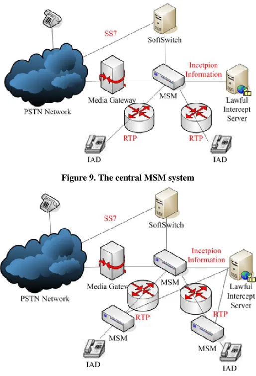
Figure 8. Distributed System for Lawful Interception Diagram "Legal Call Interception in Next Generation Networks [10]" breaks the electronic surveillance into three categories: communication contents, call identifying information and the store of the transaction records. Only less equipment assist the service provider becoming CALEA (Communication Assistance for Law Enhancement Act) compliant right now. So the thesis also provides the following two solutions for this issue. The MSM (Multi-Service Mediator) can analysis the call information and redirect the data to a lawful interception server. The network architecture could be centralized or distributed. The centralized system will do the interception by a single MSM. And pass the messages to the lawful interception Server. In the distributed MSM environment, each MSM could transmit the interception information to the interception server independently. Our system architecture will similar to the centralized MSM system. We just want to intercept the specific user. Not to monitor all of the users in the network.
Figure 9. The central MSM system
Figure 10. The distributed MSM system
“A Brief Overview of VoIP Security [11]” mentioned many free network analyzers, sniffers and packet capture tools. We can convert the VoIP traffic into wave files. “VOIP HACK: Tips & Tools for Internet Telephony [12]” also introduced some existing program for the VoIP call interception. We can use tcpdump and Vomit (Voice over Misconfigured Internet Telephones) to achieve this goal. We can also use the Cain & Abel to sniff a SIP call. Cain & Abel can corrupt the MAC table to get traffic of other machine. These studies provide
us some toolsets for the VoIP network attack and inspection. We’ll setup the toolsets and use it to attack the VoIP network, and analysis the behavior. Reference to the behaviors can help us to develop our system.
“HACKING EXPOSED VoIP [13]” is the most important reference book for us. It not only introduced varies skills to break the VoIP network, but also defines various architectures for the VoIP interception. We’ll implement some interception models into our system with our own mechanism. The following is the description of the concepts.
The first one is the SIP Proxy Attached. It is running a program in SIP proxy, and the program will trace the signaling and redirect the call. To achieve this goal we can use register hijacking tool to highjack the registration for a key SIP phone user and redirect the phone. The following figure is the topology.
Figure 11. The SIP Proxy Attached Interception
The second architecture is the Rouge Back to Back User Agent. Rogue SIP Back to Back User Agent could be a user agent or a SIP phone. It can be located between SIP proxy and a SIP phone or two SIP phones. The following is the topology.
Figure 12. The Rouge Back to Back User Agent Interception
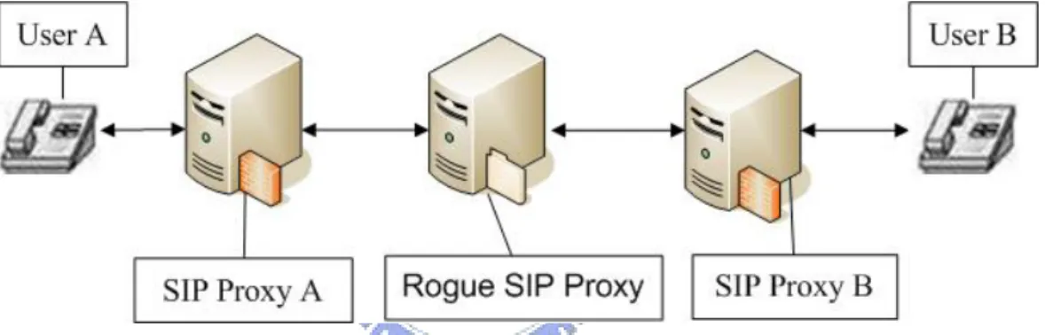
The final architecture is Rogue SIP Proxy. It acts like a SIP proxy. The fake proxy just does the transparent the information and the steal the necessary information. It can be located between SIP proxy and a SIP phone or two SIP phones. The following is the topology.
Figure 13. The Rogue SIP Proxy Interception
3.2.2 The VOIP Interception solutions of each vendor
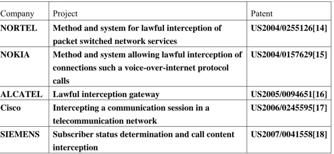
VoIP Interception is a basic requirement of the VoIP network. Government will ask the vendors to provide the solution of this function. So each vendor has their own solutions. Most of the solutions will require the infrastructure change, so government has to buy additional equipments to achieve this goal. The following table is the list of the VOIP interception solutions of each vendor and the patent number and project name. To reference these solutions of the venders is very important, because they have a strict process to release their patents. But most of them will add more equipment in the architecture. So we’ll achieve this
Company Project Patent NORTEL Method and system for lawful interception of
packet switched network services
US2004/0255126[14]
NOKIA Method and system allowing lawful interception of connections such a voice-over-internet protocol calls
US2004/0157629[15]
ALCATEL Lawful interception gateway US2005/0094651[16] Cisco Intercepting a communication session in a
telecommunication network
US2006/0245595[17]
SIEMENS Subscriber status determination and call content interception
US2007/0041558[18]
Table 8. The VOIP interception solutions of each vendor
All of the listed service providers are powerful venders, and can push their solution hardly. Even it the network infrastructure should be changed. But we didn’t know the
interoperability of each solution, because there might be some conflicts of each solution. And most of the solutions contain a complex call flow or many additional servers in the networks to intercept the messages. Compare to our target, our solution is to keep the original network architecture. Keep the original call flow, and uses software based tools to do the interception. Keep the original architecture of the IP telephony, and try to provide more flexibility for the users. And the software based tool set can also cost down to do the interception. That’s the differences between the patents.
Chapter 4 The FIVE System
This chapter is the description of the FIVE system implementation details. We’ll introduce the design guideline and the system structure. And also introduce the libraries that we used for network programming. All of the algorithms will be implemented in this system and do the validation. The FIVE system means “Flexible Interception in VoIP Environment”. We provide the flexible interception mechanisms to do the lawful VoIP interception. And there will be five different interception models to be described in this chapter. And the software based system will reduce the cost of interception equipment, but still provide the reliable interception quality.
4.1 System Overview
The target of the system is to do the analysis of the VoIP calls and do the interception. We can divide the FIVE system into three functional blocks. And in this section we will describe the design concept. Reference to the following topology that we discussed previous chapter, the red cycles is the access point to do the interception and we provide five different models for the interception.
4.1.1 The System Architecture
The target of the thesis is to create a software based VoIP call interception system. We have designed some algorithms and state machines for different interception models. In FIVE system, there will be three major modules in this system. The following is the block diagram of our system. The decision center is the core to do the analysis and make the decision. The packet capture module is the network traffic access module. And the restore to disk module is to save the information to the storage.
Figure 15. System Block Diagram
The three capabilities is the capability to send and receive a packet, the capability to restore the data to storage and the capability to analysis the packet, and do the reaction. The normal interception procedure is as followed. The packet capture module will keep polling the packet from the network, and send it to the decision center. The decision center will analysis the packet and decides what to do. The decision center will send out a packet to trigger some event or to send the original packet to ring buffer. The restore module will write the RTP payload into the hard disk.
The decision center has different state machines to do the analysis and make the decision. This module will do the protocol analysis and decision making. For performance concern, we would create two tasks to maintain the packet polling and data restore to the hard disk. And the data will pass by a public ring buffer. A public ring buffer is declared by the CRingBuffer
data structure. The ring buffer is used to restore the RTP packet payload. And another task will get the raw data and save it to the disk as a media format file. And the save to disk is using normal file I/O function call.
4.1.2 The Programming Environment
We use the Microsoft Visual C++ for the programming environment. It is an integrated development environment (IDE) product provided by Microsoft. The followings are the reason that we choose it for the environment. First is it provides a feasible and powerful
environment to implement a system with GUI. It provides many general and reusable modules. The second reason is the WinPCAP provides great library to support the network package processing ability. And last reason is that in the new embedded system like WINCE will support .Net framework program. So we will have the chance to put our FIVE system into some portable devices with the WINCE or Windows Mobile OS. The follow diagram is our develop environment.
4.1.3 The Windows Packet Capture Library
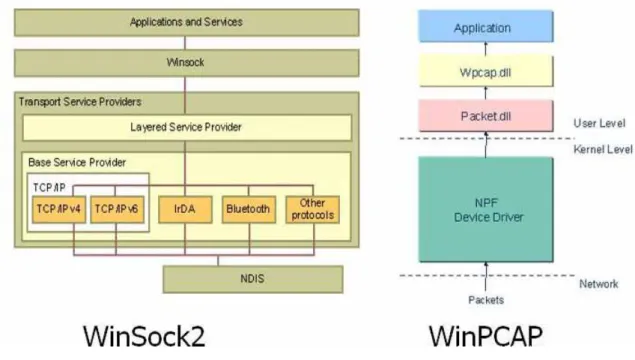
The network packet capture function is very common. Most of the programmers will create a raw socket to sniff the packet. And also use the socket to send the packet. This is base on the Winsock2 library. But Winsock2 can only support the function above the IP layer. We need the MAC layer information, so we choose another solution. WinPCAP, the Windows Packet Capture Library is our solution. It allows the network programmer to access the MAC layer information, and create more flexibility for the network programming. The following diagram is the compare of the two architectures:
Figure 17. The WinSock2 and WinPCAP architecture
To use the WinPCAP library in Visual C++ programming is also very easy, the
programmer just have to include the PCAP library and then to use the library. The WinPCAP provides us the ability to capture the more details about a network packet, and most important of all is that we can change the source and destination IP and MAC to any value we want. The wireshark also use the PCAP library to do the packet capture.
Figure 18. Wireshark Packet Capture Window
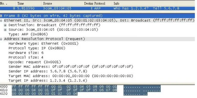
In the wireshark log we can see that, it is a spoofed ARP request packet creates by our system. The values of the IP and MAC address could be modify by us instead of real MAC address of our NIC. So we can use the fake ARP or IP packet to corrupt the target machine to control the routing of the packet.
4.1.4 The Packet Process Mechanism
For the flexible interception, we need to do some modification of the network packet that we have captured. And redirect it to the target machine that we want. We can also modify the register content. We will create a thread to keep polling the network packets and receive all of it to do the processing. After received a packet, FIVE system will parse the packet content, and following the interception state machine to decide the reaction of our FIVE system. Sometimes we have to redirect the packet, or modify the SIP content. After the modification, we still need to correct the IP and UDP checksum. Or the packet will be dropped because of the incorrect checksum. We can take the following Packet Processing Mechanism diagram as example. The FIVE System State Machine will check the content of the packet and make the decision following the state machine. And if the packet is the RTP packet that we want to
Figure 19. FIVE System Packet Processing Mechanism diagram
4.1.5 The Packet Restore Mechanism
Reference to previous section, the binary raw data of the RTP packet will be put into a ring buffer. At the same time, we use a stack to maintain the packet length information. Every time when we put a packet into the ring buffer, we will also push the length of the packet into the stack. We will create a new thread to write the ring buffer content into the file system as a file. The following diagram is the flow chart of this thread. The thread will push 0 to stack for initial the stack, and do the pop from stack periodically to see if any data needs to write into the file system.
4.2 FIVE System Interception Mechanisms
The different interception model is with different intercept mechanism. This section will discuss the mechanisms. The mechanisms will analysis the SIP protocol flow and do the interception. Then we’ll maintain different state machine for each different model and to perform the interception.
4.2.1 The Rouge Back to Back User Agent Interception
The system can be configured as different modes to support different interception models. The first model is the Rogue B2BUA Server. The system is running as a SIP proxy server and also a SIP proxy. And the User will be register to the rogue server as the SIP proxy. The B2BUA server will register to the real SIP proxy. The following is the diagram of this model:
Figure 21. The Rogue B2BUA Server Model
The Rogue B2BUA server is to spoof a proxy server and make the target VoIP phone to register to this server. The following is the flow chart of incoming call and outgoing call interception. In the diagram, the USER B is the target to be intercepted. All of the signaling command to the User B or from the User B will pass through the Rogue B2BUA server. So the Rogue B2BUA server could easily detect the VoIP call and redirect the call by modifies the SDP protocol content.
Figure 22. The Rogue B2BUA Server Incoming Call Interception flow
Figure 23. The Rogue B2BUA Server Outgoing Call Interception flow
To achieve this goal, the end user should register to a fake SIP proxy spoofed by our system. The following is the SIP register procedure of the Rouge B2BUA Server architecture system. The end user will send the register command to our Rogue B2BUA Server, and we will modify the register command content to make our Rogue B2BUA Server just like IAD to register to the real SIP proxy. In the SIP proxy point of view, the Rogue B2BUA Server is a IAD, and in the end user point of view, the Rogue B2BUA Server is the SIP proxy. Our Rogue B2BUA server will be the bridge to forward and modify the content of message.
Figure 24. The Rogue B2BUA Server Register flow
And then we can forward the conversation of the end user to our server by modify the SDP information.. The following is the flow of the SDP modification. The SIP call will separate the signaling and voice flow, so we need to redirect the RTP packet to our interception server. The Rouge B2BUA Server will forward it to the end user.
Figure 25. The Rogue B2BUA Server SDP exchange flow
being intercepted.
Figure 26. The Rogue B2BUA Server Interception RTP flow
The state machine reflects the reaction of the FIVE system in the Rogue B2BUA Server Interception. The upper part of the state machine is the register control. The incoming and outgoing call will have different procedure to do the interception. The key point of the Rogue Server Interception is to redirect the traffic to the Interception Server by modify the content of SDP.
4.2.2 The Rouge SIP Proxy Interception
The second model is the Rogue SIP Proxy mode. The rogue SIP proxy will acts as a normal SIP proxy. The SIP signaling protocol will be exchanged between SIP proxies. The rogue SIP proxy will intercept or modify the message to perform the interception. The following is the diagram of this model:
Figure 28. The Rogue SIP Server Model
In the SIP VoIP network, the signaling will pass by the SIP proxy servers. The User B is the target that to be intercepted. In this topology, the Rogue SIP Proxy will play like a normal SIP proxy. But also collect the necessary information or to modify the signaling content to redirect the call information. So the best position of the Rogue SIP Proxy is the next hop of the Proxy B. Because we won’t loss any calls between these two proxies. The following diagrams are the incoming call and outgoing call flow.
Figure 29. The Rogue SIP Server Incoming Call Interception flow
Figure 30. The Rogue SIP Server Outgoing Call Interception flow
The Rogue SIP Server interception has different procedure with the Rogue B2BUA Server. Rogue SIP Server is an SIP proxy that the target user not registers to. So we didn’t need to modify the SIP register procedure. But we still need to modify the SDP content to forward the RTP flow to our interception server to record. The following diagram is the SDP modification of the intercepted call.
Figure 31. The Rogue SIP Server SDP exchange flow
Because of the SDP information is modified, all of the RTP flow will be redirect to the Rogue SIP Server and being recorded. And in the following diagram we will see that the call was redirected to the interception server.
Figure 33. The Rogue SIP Server State Machine
Reference to the Rogue SIP Server state machine, you will see that it looks like the previous state machine. The difference is that the Rogue SIP Server is located between SIP proxies and didn’t connect to the end user. So modify the SDP to redirect the RTP is a simple way to do the interception.
4.2.3 The SIP Proxy Attached Interception
The SIP Proxy Attached Model is running our FIVE system in the SIP Proxy. FIVE system can intercept the information directly from the proxy server and pass the necessarily information to a remote monitor server. The following is the diagram of this model:
Figure 34. SIP Proxy Attached Model
The SIP Proxy attached mode is to install our FIVE system in the Proxy server. The network module will receive every message to send to this server. In this model we will use a SIP protocol 302 redirect message to make a third-party call. The remote Monitor Server will be the third-party to receive the call. It didn’t send out any message but just listen to the conversion. There are several advantages of this interception mode. This is the most directly way to do the interception. And the Proxy B can also do the interception by itself. The following diagram is the flow of the incoming and outgoing calls.
Figure 36. The SIP Proxy Attached Incoming Call Interception flow In this model, our system is attached to the SIP Proxy server. So we can send the SIP signaling command to make the end user redirect the call. The following diagram is the sample of the redirect VoIP call by SIP 302 Moved Temporarily Response. The Moved Temporarily command often used by the redirection server to inform the user that the user have been moved, and also tell you the correct address. This is also protocol vulnerability for us to use as an interception method. From the following diagram we can see that, a user A wants to call user B. The Redirect Server asks the user A to redirect the call to new address New user B. In our interception scenario, the new user B will be the Monitor Server in the Figure 31 and 32. The Monitor Server will call to the real target that user B. And the voice will be intercepted.
To do the SIP Proxy attached interception is different from the previous solution. Our FIVE system is in the SIP proxy. The SIP proxy can receive the entire signaling packet, but the signaling path and the voice path are separated. We still have to redirect the RTP flow to pass to our interception server. Because of the loading of the Proxy Server to being a SIP proxy and an interception server at the same time will be too heavy, so we’ll suggest
redirecting it to another interception server. The following diagram is the modification of the SIP Proxy attached interception. And the call and interception flow please reference to the Figure.30.
Figure 39. The SIP Proxy Attached Interception State Machine The SIP Proxy attached Interception is different mechanism of the FIVE system. Because it is already attached in the SIP proxy, so to get the enough information is not the most concern. By the useful PCAP library, we can intercept any network traffic before it be send to the application. We can also send a fake command to any user or cheat the attached SIP Proxy by send a fake command to itself. That’s why we will try to use a SIP 302 move temporarily command to redirect the call to our Interception Server. And we will suggest not restoring the traffic in the attached SIP Proxy, because the loading might cause the unstable service of the SIP Proxy. We can easily to off load by redirect the RTP to the Interception Server.
4.2.4 The Remote Attack Interception
The remote attack model is also a different concept. Our system will be a remote
Interception Server. The remote attack will attack both SIP Proxy and the end user, and hijack the register of the end user. After all, we can do the interception of end user by spoofing the end user. Reference to the following model, the Interception Server will do the register hijacking to the SIP Proxy, and also do the ARP spoofing to the end user to get the packets that transmit out of the end user.
Figure 40. The Remote Attack Model
The Remote Attack is using the network attack skill to cheat the target user to redirect their traffic to our interception server. Our target is to use the ARP spoofing to modify the ARP table of a user, and redirect all of the traffic to our interception server.
To do the ARP spoofing, we will use a fake ARP reply command to corrupt a target machine’s ARP table. If we can control the ARP table, we can control the routing of the traffic. The following is the evaluation of the ARP spoofing, in the network have a PC IP address is 192.168.1.3 and MAC address is 00-16-41-52-d2-10. Our interception server IP address is 192.168.1.3 and MAC address is 00-0c-6e-43-14-e4. The following is the ARP table in the computer.
Figure 41. ARP table before ARP spoof attack
And then we perform the ARP spoof attack from the interception server, to send out a fake ARP reply command make the target machine to overwrite the ARP table. The following is the fake ARP reply capture log from the Ethereal.
Figure 42. The ARP spoof attack log
And the following figure is the ARP table after the ARP spoofing attack. When the target machine try to send the message to 192.168.1.3, it will send to the MAC address of
192.168.1.1, that is our interception server. By this kind of direction, we can redirect all of the traffics to our interception server.
Figure 43. ARP table after ARP spoof attack
The register hijacking is also a part of the remote attack model. The register hijacking is to register to the Proxy Server by a spoofed register request. And then we can redirect all of the signaling and voice command to the Interception Server. The following diagram is the sample of the register request from the user agent to the SIP Proxy Server. Please notice that the contact item, the contact address is where the call should be forward to. So the register hijacking is to send a spoofed register request to the SIP Proxy with the modified contact information. For example, we can send a fake request command with contact IP address 192.168.0.4, our Interception Server. If the register is success, all of the incoming call will be redirect to the 192.168.0.4.
@>zjEYBFEREGISTER sip:192.168.0.1 SIP/2.0 Via: SIP/2.0/UDP
192.168.0.2:17948;branch=z9hG4bK-d87543-9143986d8b30b640-1--d87543-;rport Max-Forwards: 70
Contact: <sip:[email protected]:17948;rinstance=311293041eafa42b> To: "12345678"<sip:[email protected]> From: "12345678"<sip:[email protected]>;tag=df556f31 Call-ID: ca67b01b2a520546MWMzM2UyYzg3MTliYmMzNmJlMTg0NWIwMWRhMzJjYWQ. CSeq: 1 REGISTER Expires: 3600
Allow: INVITE, ACK, CANCEL, OPTIONS, BYE, REFER, NOTIFY, MESSAGE, SUBSCRIBE, INFO
User-Agent: X-Lite release 1002tx stamp 29712 Content-Length: 0
Figure 44. SIP Register Request
The following diagrams are the remote attack interception model. First the Remote attack Server will do the register hijack to the Proxy B. And then do the ARP spoof attack to the User B to make the Proxy B think the Remote Attack Server is the user B. And also make the User B think the Remote Attack Server is the Proxy B. So the Remote Attack Server can intercept all of the RTP packets during the call.
Figure 45. The Remote Attack Outgoing Call Interception flow
Figure 46. The Remote Attack Incoming Call Interception flow The first step is to do the register hijacking to the SIP Proxy, and also do the ARP spoofing to make the end user redirect all of the traffic to our Interception Server. And the following steps will be the same as the Rogue B2BUA Server interception. Or another solution is doing the ARP spoofing as the gateway for the end user. And do the register hijacking to the SIP proxy. And then all the incoming call will pass to the Interception Server, the outgoing call setup of end user will send Interception Server. We can modify it as our call setup request.
Figure 47. Remote Attack State Machine
4.2.5 The Port Mirroring Interception
The final model is the port mirroring interception model. The concept of the port mirroring interception is very simple. To redirect the traffic of specific user’s to a port. A successful interception should make the user not aware the interception is processing. The difference between Remote Attack Interception and Port Mirroring Interception is the Port Mirroring Interception is the pure network interception to the end user. It is not related to the SIP protocol just to get everything to our Interception Server. But Remote Attack Interception is still trying to do the register hijacking by the SIP commands.
If the user is connecting to a switch, our “FIVE” system can do the ARP poisoning attack of switch. A switch can do the packet switching, and it is the major difference from the hub. But the internal ARP table of the switch is always have limitation, so the ARP poisoning is using a lot of random ARP replies to corrupt the ARP table of the switch, and then the switch will just work like a hub. Out interception server can just connect the same switch to sniff the packet and do the analysis and record. The following is the wireshark log of the “FIVE” system is doing the ARP poisoning attack.
Figure 48. ARP poisoning attack
Or we can do the port mirroring interception by the special configuration of the network device. For example the port mirroring functions of the switch. Port mirroring is to copy all of the traffic and send to another port to do the monitor. And the purpose is the intrusion
detection or network traffic monitor. If the end user connect to this kind of switch and enabled the port mirroring function, our “FIVE” system can connect to the mirror port and do the call analysis and record. Some of the Cisco switches support this function can name it Switched Port Analyzer (SPAN). The following is a diagram of the port mirroring interception.
After the Interception received all of the packets, we can do the analysis easily by using wireshark or any other SIP call analyzer. The following diagram is the graphical analyze result of the wireshark. We can check the protocol flow of the VoIP calls, and even to replay the voice by player that wireshark provided. It is just like to do the packet collection in the end user’s IAD.
Chapter 5 Experimental Result
In this chapter we will setup a real experimental environment to evaluate thefunctionality of our system. And also verify the side effects of our FIVE system. After setup a real VoIP network environment, we tested our interception function, and record the details of the test result and logs. We also finished the analysis of the test result, and try to fine tune our system. At first we will introduce our experimental environment. We have a simple but complete VoIP network test bed and get the test result of each case. After all we will do the analysis of the test result. To evaluate the system performance is very important, because the quality of telecomm service should be very stable. So our interception could not affect the normal service. This is the most challenge. And the details of the test result also could be the reference of the future work for who is interest of this subject.
5.1 Experimental Environment
The following diagram is our test environment diagram. Two PCs simulate the SIP proxies and another two PC simulate the IAD. The Interception Server is the server to
perform the interception. The black line is the physical link, and the red line is the logical link. And the Interception Server logical link depends on which interception mode it supports.
The environment is to simulate a small VoIP environment. The Proxy Server is running the OnDo SIP Server application, and the IAD is running the x-lite application to simulate a SIP phone. The following table is the specification of each device.
Device Name Specification SIP Proxy A IAD A SIP Proxy B IAD B IBM T43 CPU: DOTHAN 750(1.86GHz) RAM:DDRII 533 512 MB Harddisk: 80G Interface, 7200 rpm Operation System: Windows XP Interception Server Lenovo Thinkpad X60
CPU : CoreDuo T2300(1.66GHz) RAM: DDRII 667 1024 MB
Harddisk: 160G SATA Interface, 5400 rpm Operation System: Windows XP
Switch Marvell 88E6095 Chipset
Table 9. Testing Environment Device Specification
5.1.1 SIP Proxy – OnDO SIP Server
The SIP proxy is a computer running Brekeke OnDo SIP server. The software version is 1.5, and using the OnDo SIP Server with the Evaluation Use license.It is a SIP Proxy and Registrar and the environment needs the JAVA runtime environment 1.4 support. I used it for registers and authenticate users, and routes calls between user agents. And the two SIP
proxies to simulate the signaling message transversal between Proxies. The IAD A will configure to register to SIP Proxy A, and IAD B will configure to register to SIP Proxy B. If we want to make a call from IAB A to B, the call setup should be complete by the co-work of
proxy and try to setup the call. The following diagram is the register list, that a soft SIP phone is register to this server.
Figure 52. OnDo SIP Server Registered List
5.1.2 IAD – X-Light
X-Light is a popular free soft phone using in the VoIP network. We use it to simulate an IAD to make the SIP call. The configuration is also very easy. Just to create an account with username and indicate the target domain. When start up the application, the X-Light will try to register to the target SIP proxy. And then you can make the VoIP call.