1088 IEEE PHOTONICS TECHNOLOGY LETTERS, VOL. 12, NO. 8, AUGUST 2000
A Novel Optical Label Swapping Technique Using
Erasable Optical Single-Sideband Subcarrier Label
Y. M. Lin, W. I. Way, Senior Member, IEEE, and G. K. Chang, Senior Member, IEEE
Abstract—To support optical MultiProtocol Label Switching
(MPLS) technology in an optical network, we have demonstrated subcarrier label swapping in a 96.2-km, three-node experiment, by using optical single-sideband modulation and an optical notch filter. At each intermediate switching node, an old subcarrier label can be suppressed by 25 dB, while the burst-mode 2.5-Gb/s payload experienced only 2-dB power loss.
Index Terms—All-optical label swapping, all-optical networks,
IP over WDM, optical IP, optical packet switching.
I. INTRODUCTION
M
ULTIPROTOCOL Label Switching (MPLS) technology [1] is the key to improve the scalability, speed, and throughput of the current Internet networks. MPLS switches use a simple label-swapping algorithm to quickly forward packets. Here a label is composed of a short fixed length of bits, and is used to save significant processing time by avoiding net-work-layer label analysis at each hop. “Label swapping” means that a “locally significant” old label is replaced with a new label at each MPLS switch. High-capacity DWDM optical networks are expected to support MPLS technology. However, significant technical challenge exists in updating optical labels on the fly without affecting data payload. Recently, several complicated optical label-swapping techniques have been demonstrated [2], [3]. In this paper, we propose a novel technique to simplify and enable numerous repeated optical label swapping over a national optical network, while, in the meantime, keeping the multigigabit-per-second data payload intact.II. OPERATIONPRINCIPLE
Our scheme is based on a subcarrier label (e.g., 155 Mb/s on a microwave carrier) which is frequency-divison-multiplexed with a baseband data payload (e.g., 2.5 Gb/s). The subcarrier label swapping is accomplished by first having it erased in the optical domain, and then remodulate the light with a new sub-carrier label at the same microwave sub-carrier frequency. To erase the old subcarrier, we took advantage of a notch filter by using the reflective part of a voltage-tunable fiber Fabry–Perot (FFP) filter, as shown in Fig. 1. However, we note that the optical
Manuscript received December 17, 1999; revised April 13, 2000. This paper was supported in part by DARPA under Contract F30602-98-C-0216, and is in part by the Ministry of Education (under the Program of Excellence Research) and Lee & MTI Network Research Center.
Y. M. Lin and W. I. Way are with the Department of Communications En-gineering, National Chiao-Tung University, Hsinchu, Taiwan, R.O.C. (e-mail: [email protected]).
G. K. Chang is with the Telcordia Technologies Inc., Red Bank, NJ 07701-5657 USA.
Publisher Item Identifier S 1041-1135(00)06244-3.
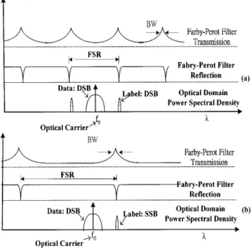
Fig. 1. Optical notch filter responses and optical spectra for: (a) ODSB and (b) OSSB subcarrier labels.
double sidebands (ODSB) of the data payload and subcarrier label are located on both sides of the optical carrier, as illus-trated in the lower part of Fig. 1(a). To erase the subcarrier label, both subcarrier sidebands must be notched out. But this requires that the free spectral range (FSR) of the filter be ex-actly equal to the separation of the two subcarrier sidebands. Furthermore, the notch filter must present a sharp and narrow notch so that the data payload is not affected. Consequently, it is difficult to design and manufacture a FFP filter which satisfies both requirements. To solve this problem, we propose using op-tical single-sideband (OSSB) modulation technique [4] to trans-port the subcarrier label, so that the resultant optical spectrum contains only one subcarrier label sideband, as shown in Fig. 1(b). Another important advantage of using OSSB microwave subcarrier label is that, by avoiding the fiber dispersion-induced carrier suppression effect [4], its transmission distance between switching nodes can be more than several hundred kilometers
without dispersion compensation.
III. EXPERIMENT ANDRESULTS
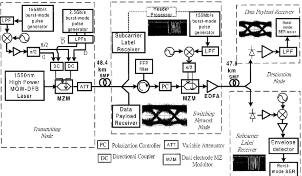
Our experimental setup for transmitting, destination, and in-termediate switching nodes is shown in Fig. 2. In the transmit-ting node, a 50-mW 1551-nm DFB-MQW laser and a two- elec-trode LiNbO external Mach–Zehnder modulator (MZM) with
LIN et al.: A NOVEL OPTICAL LABEL SWAPPING TECHNIQUE 1089
Fig. 2. Experimental setup.
a 3-dB bandwidth of 20 GHz and an insertion loss of 4 dB were used. A bursty 155-Mb/s ASK subcarrier label at 12 GHz was applied to a hybrid coupler whose two outputs have phase shift with respect to each other. These two outputs were then combined with a bursty 2.5-Gb/s data and data invert, respec-tively, through two-directional couplers. Note that the label and payload bursts were both randomly generated, with each label and payload burst consisting of 20 bits and 53 bytes, respec-tively. Two lowpass filters (LPFs) with a 3-dB bandwidth of 2.4 GHz were used to prevent the tails of the 2.5-Gb/s NRZ data from interfering with the ASK subcarrier. The two combined NRZ data and ASK subcarrier outputs were then used to drive the two electrodes of the MZM, respectively. Fig. 3(a) shows the spectrum of the transmitted baseband 2.5 Gb/s data and the ASK microwave subcarrier label.
In the switching node, the received optical signal was split into three paths. The first path was simply a data payload receiver which consists of a 50- -terminated photodiode, a dc–14-GHz amplifier, and an LPF. The second path was a label receiver which consists of a 50- -terminated photodiode, an 8–12-GHz amplifier, a downconverter with IF frequency at 550 MHz, and an ASK envelope detector. The eye diagram of the received data payload and the bursty 20-bit label are shown in the insets of Fig. 2. The third path was the path where the label swapping took place. The optical signal was reflected by an FFP filter via an optical circulator, so that the old subcarrier label was notched out. The FFP filter had an FSR of 1500 GHz, a finesse of , and a reflection loss of 1.5 dB. Fig. 3(b) shows the after-notching microwave spectra. We can see that the subcarrier label at 12 GHz was suppressed by 25 dB, while the 2.5-Gb/s payload experienced only 2-dB loss. The optical signal which had its subcarrier label suppressed subsequently passed through a polarization controller and another MZM. At the MZM, the optical signal was remodulated with a new ASK subcarrier label, which had the same carrier frequency and
Fig. 3. Spectrum analyzer displays (a) before and (b) after the OSSB subcarrier label is suppressed.
optical modulation index (OMI) as those of the old subcarrier label. At the output of the switching node, an EDFA with an output power of 12 dBm was used. Note that the lengths of the first and second fiber spans in Fig. 2 were 48.4 and 47.8 km, respectively. In the destination node, the same data payload and subcarrier label receivers as those in the switching node were used. The bit-error rate (BER) of the payload and the label were measured by a burst-mode BER tester (BERT).
1090 IEEE PHOTONICS TECHNOLOGY LETTERS, VOL. 12, NO. 8, AUGUST 2000
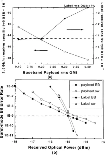
Fig. 4. (a) 2.5 Gb/s and subcarrier label receiver sensitivities as functions of the 2.5-Gb/s rms OMI. (b) Burst-mode BER versus receive optical power for 2.5-Gb/s payload (random, bursty 53-byte sequence), and for subcarrier label (random, bursty 20-bit sequence) before and after remodulation.
With its burst clock and trigger, the BERT can synchronize the received payload or label pattern to the stored pattern such that the corresponding BER per burst can be obtained. The bursty 20-bit sequence of the received new subcarrier label (after one-time label swapping and 47.8 km of transmission) and the eye diagrams of the baseband payload (after 96.2 km of transmission) are shown in the insets of Fig. 2. Since 25 dB of the old label power was suppressed by the notch filter, the residual old label had negligible effect on the remodulated new label. However, the CNR of the new label was degraded by the intermodulation noise caused by the beating between
the baseband data and the new subcarrier label. This CNR degradation resulted in power penalties in receiver sensitivity, and was dependent on the rms OMI of the baseband data. In our experiment, assuming that the data payload receiver and the ASK subarrier label receiver required the same received optical power, and the ASK subcarrier label’s OMI was 17%, we obtained the optimum rms OMI of the baseband data at 20%, as shown in Fig. 4(a). Under this condition, there was less than 0.5-dB power penalty (for BER ) when comparing the burst-mode BER performance of the bursty subcarrier label before and after remodulation (which is due to the intermoulation noise just mentioned), as can be seen in Fig. 4(b). The bursty 2.5-Gb/s payload was essentially unaffected by the switching node, as can be seen from the burst-mode BER’s before and after label swapping.
IV. CONCLUSION
We have experimentally demonstrated a novel subcarrier label-swapping technique by using OSSB modulation and an optical notch filter. The effect of residual old label on the new label was negligible because the old subcarrier label could be suppressed by 25 dB at each switching node. The subcarrier receiver power penalty due to the intermodulation noise between the baseband data and the new subcarrier label was within 0.5 dB at each hop. The label swapping can be repeated numerous times over a long-distance network without dispersion compensation because the subcarrier label is reset at each switching node and because of the inherent transmission advantage of OSSB modulation. For practical implementation of the current technology in optical networks, we are currently resolving the MZM polarization-sensitive issue, and the result will be published shortly.
REFERENCES
[1] IETF. (1999, July) Internet Draft. [Online] Available: http://search.ietf. org/internet- drafts/draft-ietf-mpls-framework-04.txt
[2] D. J. Blumenthal, A. Carena, L. Rau, V. Curri, and S. Humphries, “All-optical label swapping with wavelength conversion for WDM-IP net-works with subcarrier multiplexed addressing,” IEEE Photon. Technol. Lett., pp. 1497–1499, Nov. 1999.
[3] X. Jiang, X. P. Chen, and A. E. Willner, “All optical wavelengh in-dependent packet header replacement using a long CW region gener-ated directly from the packet flag,” IEEE Photon. Technol. Lett., pp. 1638–1640, Nov. 1998.
[4] G. H. Smith and D. Novak, “Broad-band millimeter-wave (38 GHz) fiber-wireless transmission system using electrical and optical SSB modulation to overcome dispersion effects,” IEEE Photon. Technol. Lett., pp. 141–143, Jan. 1998.