Vibration Analysis of Rolling Piston-Type Comprcssors Driven by Single-Phase Induction Motors
Chung-Ming Young and Chun-Chang Liu
Deprtment of
Electrical Engineering
National Taiwan University
Taipei, Taiwan 10672
Abstract
Rolling piston-type compressors [l], [2] driven by single-phase induct,ion mo-
tors are widely used in low power room air conditioners. Since a rolling piston-type compressor represents an eccentric load to the mot.or, vibration problems associated with the compressor and motor drive assemhly always occur. Furthermore, for ease of darting, a single-phase induction motor is usually designed with unsymmetrical stator windings, which is far more difficult to be analyzed as compared to a typical symniet,rical t.lirec-phase indnction motor. This paper est.ahlislies t,he state-space model for a rolling piston-type compressor driven by a single-phase i n d u d o n motor. An in- verter is proposed for driving t,he motor-compressor assembly. By varying the line frequency and voltage magnit.ndes on both primary and secondary windings of the induction mot.or, this paper seeks t.o reduce t.he vibration accompanied with the motor-compressor assembly of a room air conditioner. The paper presents some useful design crit,eria for reducing vibrations based on computer simulation result,^.
I. INTRODUCTION
Rolling pist,on-t.ype compressors driven by single-phase i n d u d o n mot,ors
are widely used in room air conditioners. Since a rolling piston-t,ype compres- sor represents an eccent.ric load t.0 t,he mot,or, vihration problems associat.ed wirh the compressor and motor drive assembly always occur. The major vibration sources in a rolling piston-type compressor include load torqne and radial force variat.ion due t,o gas compression, bending v i b d i o n due to unbalanced inert.ia of shafts, mot,ion of int,ernal elements such as discharge valves and vanes, and motor torque variation [l]. These vibrat,ion sources
generate audible noises and came maint,enance problems such as damage to the mechanical assembly due to long term operat.ion.
In a conventional room air conditioner, the compressor is usually driven by a single-phase induction mot.or due t,o its low cost and wide spread use in home appliances. Though recent air conditioners have used brushless dc servo motors to drive compressors, the application has not yet gained major market share. Single-phase induction mot,or drives are still the dominant drives in providing driving torqnes for compressors that are used in low power home appliances. Due to compressor characteristics as described in the previous paragraph, it is imporhnt to establish a mathematical model that describes the compressor-motor dynamics and then, using this model, to design a better controller for reducing vibrations and noises. To reach this goal, the state-space model for the compressor-motor assembly is estab- lished in Section 11. Both the mot,or and the compressor are represented by nonlinear dynamic equations. In the case of the compressor, the required torque varies nonlinearly wit,li the angular shaft position a t each st,eady-state operating speed. The generat,ed torqne of t.he single-phase indrict.ion mot.or also fluctuat,es with time, as t,he motor has unsymmetrical primary and aux- iliary windings. The resuhant mot.or-compressor speed shows larger speed variation and hence vibration than those of a compressor driven by either a brushless dc motor or a three-phase symmet.rical winding induction motor.
To reduce speed variation and assembly vibration, a single-phase full- bridge inverter is proposed to drive the motor-compressor assembly in Sec- tion 111. The primary and auxiliary windings of the motor are connected to the two legs of the inverter. A microprocessor is used t.0 generate PWM sig- nals to the drivers of the invert,er. Using const,ant V / f control, t,he voltage magnitudes and line frequencies applied t,o the two mot.or windings can be varied. To achieve best results, the phase difference betwern t,he two volt.age waveforms are kept in quadrature to each ot.her, i.e., 90 degrees. A prerequi- site for using this approach is that the capacitor and cent,rifugal switsh are eliminated from the motor. The consequence is t,hat the performance and reliability of the motor can be increased. To evaluate the proposed drive
*This research was parlially supported by the National Science Council under grant
NSC82-0416EOll-096.
@7803-0891-3/93$03.CKI 01993IEEE
Chang-Huan Liu'
Department
of Elcctrical EngineeringNational Taiwan Institute of
Technology
Taipei, Taiwan 10672
performance as compared to other approaches, computer simulation is con- duct.ed in Section IV. The simulation st,udies several control configurations and compare their performance in terms of speed, torque, and current fluc- tuations. The aim is to choose a control configurat,ion that can reduce most motor-compressor vibrat,ions. Simulat.ion resu1t.s show that the proposed constant V / f cont,rol is a promising candidat.e. Finally, some concluding remarks are given in Section V.
11. MOTOR-COMPRESSOR DYNAMIC
EQUATIONS
The voltage and current stat,e-space equations for a 2-pole, single phase, or, more accnrately, 2-phase, unsymmetrical induction motor are formulated, in the st.ationary referenre frame, [3], as follows.
r
R. 0 0o
ir
i:. iwhere the subscripts, s, S, r, and R, denotes unsymmetrical st.ator and rotor windings. The two-axis st.ator voltages and currents are denot.ed as V;#, Vis, i,, , and i;.
,
respectively; t,he rot.or current.s are denot.ed as i; andi28.
The st?tor and rotor self and mutual reactances are given by X,,, S s s , Xir,S,,, X,,, and X,S, respectively. The stat.or and rotor resistances are given respect.ively as R , , R s , R:, and Rk. N , / N s denotes the turn ratio of
unsymmet.rical windings. w, is the rotor speed, and W ) is the base speed.
To faciliate motor shrting, a capacit,or is usnally connected in series with the auxiliary winding of the motor. The t.erm $XSS given in (1) is replaced by $ S s s
+
YPSc. Let, z =5,
which can be augmented with (1) to forma comp1et.e set, eqnations for describing the mot.or dynamics wit,li a skirting capacitor. The generated mot,or torque is
and the electrc+mechanical equation is
J L p r
P+
Bw,+
TL = T,. (3)The dynamic eqnations of a single-phase motor is more complicat,ed than t.hose of a three-phase symmet,rical winding induction motor. The un- symmetrical winding arrangement in a single-phase induction motor causes greater torque and speed fluctuations rhan those of a three-phase induc- tion motor. This is a major factor affecting the performance of a motor- compressor assembly.
The basic equation representing the rot.ational fluctat,ions of a rolling piston-t,ype compressor is defined in t,he following:
J i + TL(0) = T,(A) (4)
where J = moment inert,ia of crankshaft, TL(!) = load torqne of compressor,
T,(0) = motor ontpnt. t.orque,
0 = crank angle.
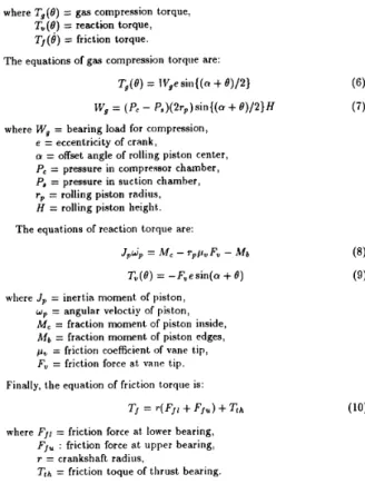
In (4) the required load torque is given by
where Tg ( 0)
=
gas compression torque,T”(8)
=
reaction torque, T,(B)=
friction torque.The equations of gas compression torque are:
Tg(0)
= lVgesin{(n+
8)/2}where W , = bearing load for compression, e = eccentricity of crank,
a = offset angle of rolling piston center,
P, = pressure in compressor chamber, P, = pressure in suction chamber,
rp = rolling piston radius, H = rolling piston height,. The equations of reaction torque are:
JpWp = M , - rppu F, - Mb
T,(Q)
= -F,esin(a+
0)where Jp = inert,ia moment of piston, wp = angular veloctiy of piston, M, = fraction moment of &on inside, hfb = fraction moment of pist.on edges, pv = friction coefficient of vane t,ip, F, = friction force a t vane tip. Finally, the equation of frict,ion t,orqrie is:
Tj = r(F,r
+
FJ”)+
TLA
(10)where F,, = friction force at lower bearing, FJ, : friction force a t upper bearing,
r = crankshaft radius,
T t h = friction toque of thrust bearing.
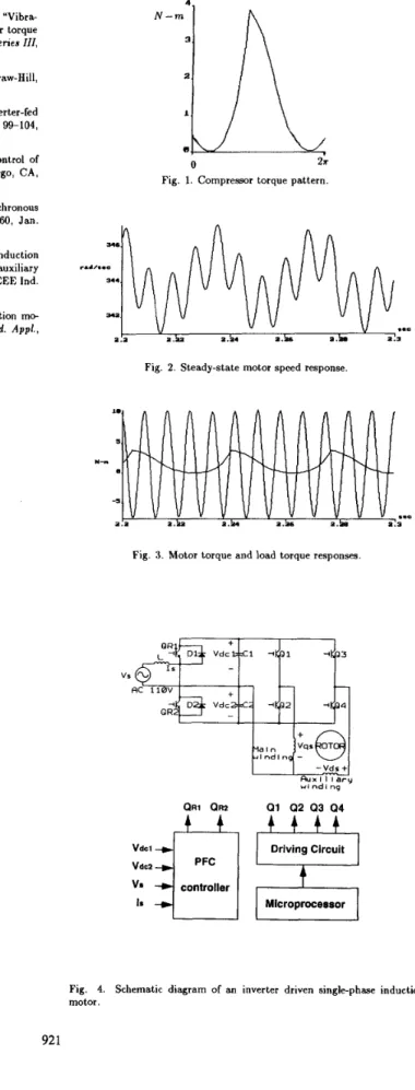
The compressor load torque serves as a torque dist,urbance to the driving motor shaft. However, it is diflicult. to use the complete motor-compressor dynamics for design and simulation, since the dynamic equations describing the compressor load torque are highly nonlinear and cont,ain several design parameters that are only availahlc to the rompressor manufacturers. For ewe of design, the torque pattrrn in one cycle operation for a certain compressor shown in Fig. 1 is saved in a lookup t.able and is used in subsequent siinrilat.ion st,udy. In each revolution, The torque is a nonlinear function of the motor shaft angular position. During simulation, the motor shaft angular position in each integration step must be known so that the corresponding compressor load torque value is obhined. Also, The parameters of the single-phase induction motor used in the simulation are listed as follows:
IlOvolt, GOHz, 2p, 1 Hp R,, = 2.020 Rs = 7.14R S,, = 66.80 R i = 5.74Q S,, = 14.5R R,, = 3R J = 0.014Glig - m2 & - N. - 1.18.
xia
= 2.79R XIS = 3.22Rx,ns
= 92.9R Xi, = 2.95R XCr = 172R Xcv = 9R R:. = 4.120 = 2.12RFig. 2 shows the st.eady-stat,e shaft speed response in rad/sec of a split,-phase induct.ion motor. The motor is connet,ec t,o bhe 60 H: llOV single-phase snp-
ply. The corresponding motor rorque a n d load t.orque responses are shown in Fig. 3. Comparing Fig. 2 and Fig. 3, when the load t.orqne is larger t.han the generat.ed motor torque, t,he motor decelerat.es; conversely, the motor accelerates. Notice the fluctual ing feat,ure of the generat,ed motor t.orque. Combining t.his wit.11 the nonlinear loading effect produces large speed varia- tion during steady-state operating condition. The resultant vibrat.ion effects
on mot.or-compressor assembly are clearly shown.
111. INVERTER CONTROL
OF
INDUCTION MOTOR
For a rolling piston-type compressor driven by a single-phase induction motor, large rotor shaft s p e d fluctuations are inevitable, which lias been
verified by computer simulation shown in the last section. By reducing speed fluctuation through certain control means, the resulant vibration of the motor-compressor assembly should also be reduced. The speed and torque variations are due to the unsymmetrical windings arrangement of the induction motor. The question naturally arises as how to choose a con-
trol method to reduce bhese variations. One obvious solution is to replace the s i n g l q h a s e induction motor by a symmertical-winding balanced three- phwe indnction motor or a dc brushless motor, since these motors have better smooth speed and torque responses. Ho\rever, a more difficult ap- proach is t o retain the single-phaqe induction motor, while seeking a control strategy to improve its running performance.
For a t.ypica1 unsymmetrical 2-phase i n d u d o n motor operated from a
fixed frequency single-phase source, the motor is always subject,ed to un- balanced applied stator voltages. In order to provide more balanced stator v o h g e s t.o t,he primary and auxiliary windings, a single-phase full-bridge invert.er is used to drive the motor. The c o n n e h o n diagram is shown in Fig. 4. The converter-inverter consists of three-leg IGBTs, in which one leg is used for redfying the input single-phase volhge and providing de voltage source to the full-bridge inverter. Two equal capacitors are connected in series across the dc input and their jnnct.ion is at a midpotintial. The other two legs of K B T form t,he single-phase full-bridge inverter, in which the upper primary and anxiliary windings are connected t.o the cent,erpoint of each leg and the both lower windings are wired together to the capacitor cen- ter junction. This circnit arrangement has the advantage of saving a diode bridge for ac-t.o-de conversion. Furthermore, using transisbors for rectifying purpose, hi-direct.ional energy flow can be achieved and, thus, nnit,y power fact.or operation can be realized. However, the unity power factor issue will not be addressed here. Instead, t.his paper will concentrate on the invert.er operat.ion and its effect.s in reducing motor torque and speed fluct,uations.
The proposition of a mot,or-compressor assembly driven by an inverter h a s the following advantages. Firstly, the cent.rifnga1 switches and external capacit.ors for starting and running that are found on many single-phase induction motor types are eliminated. since t.he st.art.ing and running of a
single-phase motor is conbrolled solely by varying inverter output voltage magnitudes and line frequencies. In fact these ext,ernal capacitors are de- signed to be operated under the nominal 60 H r condition and can be seri- ously damaged when operat,ed under high swit.rliing frequencies. Thus, the cost of motor is down and the reliability of motor is improved. Secondly, in room t.emperature cont.ro1 enviroment, using a drive which can adapt the motor speed 1.0 the act.ual cooling demands will result in higher overall system efficiency t,han a conventional inefficient. thermostatic on-off control. Thirdly, an invert,er driven single-phase induction motor drive will provide wide speed cont.rol range for varions load torque characteristics.
Many methods have been proposed in the past for designing variable speed single-phase induct.ion mot.or drives. For example, in [4] and [5], a 2-phase inverter-fed indnction motor drive is considered. The motor speed is ad- justed by cont.rolling t.lie phase difference b e h e e n t.lie two phase voltages [5] and the speed control range is fairly 1iinit.ed. (61 presents the design of an invert,er wit,h eight transistors for adjnst,ing t,he speed of a fractional horsepower two-phase symmetrical mot.or. The circuit configuration is more complicat.ed than the one proposed in this paper. [7] considers an adjiist,able speed single-phase induction mot.or drive wit,h direct angle control of the auxiliary winding supply. The primary winding is connected direct.ly to the ut.ility supply and the auxiliary winding is connected t.0 a fixed frequency voltage source of variable magnitude and phase angle. The speed control range is still limited. An adjushble vokage adjustable frequency inverter- driven single-phase induction motor drive is considered in [8]. Some valuable design information is provided. Ilowever, t,lie analysis results given in [SI are based on sinusoidal st,eady-stat.e conditions and the input. voltage source for the motor used in the experiinent,s are conduct,ed using a variable-speed synchronous generator instead of an inverter.
As shown in Fig. 4, a mirroprocesor is used for sending PWhl signals to
the t.hree legs of t.he inverter. The PU’M strategy chosen for study is the
convent,ional sine
P W M ,
which is t.he most. widely used one. To save compu- tation time, t.he firing angles corresponding to t,he int.ersection p0int.s of sine and triangular carrier waves are pre-computed and st,ored in a lookup table, Using t,lie constant V/f
control, the microprocessor computes t.he two phase stator voltage magnitudes based on the input frequency command which is generated from t.he Toom temperature regulator. In order to furhter reduce torque and speed fluct.uat,ions, the &io between the primary and auxiliary voltage magnhudes is set equal to N s / N , = 1.18. That is, t.he aiixiliary windings must sust.ain higher voltage stress Lhan t,he primary windings. The phases bet,ween the primary and auxiliary voltages are shifted by 90 degree electrical angle. This is the optimum angle for obtaining good starting and running torques and minimizing torque ripples. The computed two phaseTABLE I. AVERAGE ROTOR SHAFT SPEEDS IN RAD/SEC
I
Case 1 I1 199.5 I 230.0 I 259.1 I 288.2 I 316.3 I 344.2I
I
11
35HzI
40HzI
45HzI
50HzI
55HzI
6OHz]
TABLE 11. 35% Case 1 9.3 Case 2 15.2TABLE 111. STEADY-STATE SPEED VARIATIONS IN RAD/SEC
I
C 3 h l P U T E D SLIPS IN P E R CENT 40Az 45Hz 50Hz 55Hz 6OHz 8.5 8.4 8.3 8.6 8.8 11.7 9.6 8.0 6.9 6.1I
Case 211
186.5I
222.1I
255.8I
289.2I
321.7I
354.01
Case 4 Case 5 Case 6 13.5 11.5 10.1 8.9 8.1 7.3 10.3 8.8 7.7 6.9 6.3 5.6 10.3 8.8 7.7 6.8 6.1 5.61
Case 3/I
10.31
8.81
7.71
6.8 I 6.1 I 5.61
35112 40Hz 45112 50Hz 55Hz Case 1 5.42 8.62 10.82 13.38 16.58 Case 2 3.12 3.07 2.95 2.55 2.38 6OHz 18.11 1.98for carrier frequencies 720 H: and 7.2 I i H z , respect,ively
Case 3 1.10 1.22 1.17
Case 4 2.41 2.51 2.70
Case 5 4.35 4.35 4.35 Case 6 1.10 1.22 1.17
IV. COMPUTER SIMULATION
1.13 1.08 1.08 2.71 2.71 2.93 4.35 4.47 5.36 1.13 1.08 1.08
To gain more insight in evaluat.ing t,he performance of an inverter driven motor-compressor assembly, several cases are formnlat.ed and their perfor- mance is compared using comput.er simulation. These cases are:
1. Case 1: The motor is a split-phase type and is driven by a variable- frequency fixed magnit,ude sinusoidal voltage source. The capacibance is 183 p F .
2. Case 2: The mot,or is a capacitor st,art, capacit,or run type and is also driven by a variable-freqnenry fixed-amplit.ude sinusoidal vokage source. The start capacit,ance is 183 p F and t,he run capacitance is 15.4 p F .
3. Case 3: The mot.or is wired a s two-phase unsymmetrical and is driven by an ideal two-phase variable-frequency fixed-amplitude sinusoidal voltage source. No start or run capacitor is used. T h e phase between t,he two phase voltages is shifted by 90 degree electrical angle. This is the ideal
operating case and serves as a reference for comparing with all ot,her cases.
4. Case 4: The mot,or is two-phase unsymmetrical and is driven by a two- phase variable-voltage variable-freqiiency sqnare wave inverter. No start or run capacitor is reqnired.
5. Case 5: The motor is two-phase nnsymmet,rical and is driven by a two-
phase variable-voltage variable-frequency PWM inverter with the car-
rier frequency set a t 720 H r . No st.art or run capacit,or is required. 6. Case 6: The mot.or is two-phase unsymmetrical and is driven by a t,wo-
phase variable-voltage variable-freqnency PWM invert,er with the car-
rier frequency set a t 7.2 K H r . No start or run capacitor is required. For cases 3 to 6, t,he ratio of primary t o auxiliary voltage magnit,ude is
set equal t o N s / N . . The speed, torque, and current responses are siinnlated
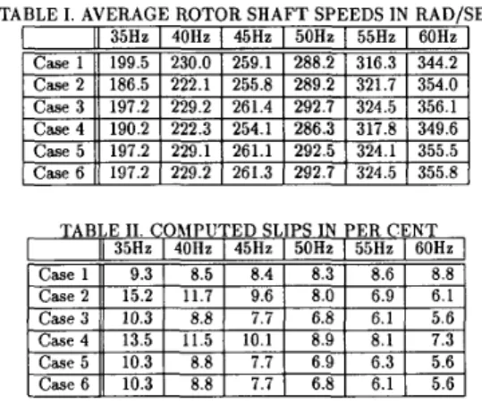
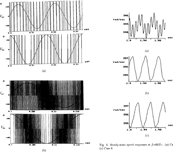
using the mot.or-compressor dynamic eqnations present,ed in Sect,ion 11. The input frequency is varied from 35 H z t,o 60 H z with an increment. of 5 H : . For f = 60Hz, the speed responses for caws 1, 3, and 6 are shown in Fig. 6. The average speed w a v e , which is the mean of peak and bottom speeds, in each case can’be calculated and, for all the cases, is tabulated in Table I. Define the synchronous speed w e = 2rf and the slip wSl as
The resultant slips for all the simulated cases are tabulated in Table 11. Also,
let Aw, be the diffence between peak and bot.tom speeds in each of t,he case
shown in Fig. 6. The speed variations for all the cases are given in Table 111. In all cases, the proposed approach (i.e., case 6) shows bet.ter perfomance, smaller slips and smaller speed variat.ions, in the frequency range form 45Hz
t o 60Hr. As t.he frequency is reduced from 35Hz t o 40Hr, t,he slip in case 6 increases in order t o maintain rated torque. Th e corresponding primary line current will also increase due t o increase slip, which is shown in Table IV. These results are ident.ica1 t o the ones presented in [8].
Next, the steady-state motor generated torque and load torque responses for cases 1, 3, and 6, are shown in Fig. 7. The proposed approach, case 6,
shown in Fig. 7 (c) reduces the generat.ed torque variat,ion quite effectively
TABLE IV. RblS VALUES O F T II E I’RIXlARY STATE CURRENTS IN AMP
11
35112I
40HzI
45HzI
50HzI
55HzI
6OHz1
I
Case 1 I1 2.02 I 2.77 I 3.94I
5.391
6.96I
7.93I
as compared t.o the conventional approach, case 1 , shown in Fig. 7 (a). In fact, the responses of case 6 and case 3, the ideal one, are almost identical. T h e torque variation, which is defined as the dilference between the highest torque value and the lowest torqiw value in a steady-st,at,e torque response, is conipnt,ed for each case and input line frequency and is tabulat.ed in Table V. Again, torque variat.ions in case 6 are the smallest and are identical to the
ones in case 3, the ideal case.
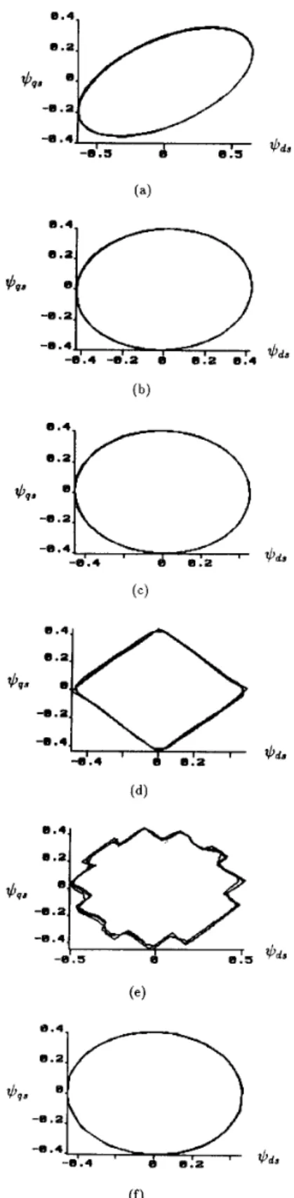
An investigat.ion of t.he steady-st,ate two-phase st.at,or flux loci can furt.her explain the performance shown in the simulat.ion cases. The staror flux loci are plot.ted in Fig. 8 for all six cases at. a operating freqiiency of 60 H r . T he skewed elliptical flux locus for rase 1 shown in Fig. 8 (a) indicat.es t,hat the magnitudes of primary and auxiliary st,ator flux are uneqnal and their phase difference is not equal t.o 90 degrees. T h e elliptical flux loci shown
in Figs. 8 (b),(c), and (f) indicate that, for cases 2, 3, and 6
,
the phase differences are all equal t o 90 degrees but the two axis flux magnibudes are not. equal. Should they be equal, t.hen circular flux loci will be obt.ained re- sult.ing in more smooth torque responses that are similar t o the symmetrical three-phase induct.ion or dc brushless motor drives. Th e square wave inverter results in parallelogram shape flux loci, while the inverter wit.11 720 Hr car- rier frequmcy yields polygonal shape flux loci; bot.11 are not good cadidates for achieving high performance single-phase indurt,ion motor control.V. CONCLUSIONS
In this paper t,he mathemabical equat,ions desrribing the dynamics of a rolling piston type compressor driven hy a single-phase induction motor provides a st,arting point for studying motor-compressor vibration and for developing a cont,rol st,rategy t,o reduce torqne and speed fluctuations and henre vibration. A variable-voltage, variable-freqnency two-phase inverter is proposed for achieving this design objective. Simulation results show t.hat the proposed inverter outperforms all the other conventional single-phase mot.or such as split phase, capacit.or d a r t capacitor run. Experimental work is now being conducted to verify the validity of the proposed inverter control met.liod.
References
[l] hi. Nakamura, H . Hat.a, Y. Nakamura, T. Endo, and K. Iizuka, “Vibra- tion reduction in rolling pist.on-t,ype compressors through mot,or torque cont,rol (basic study on theoretical analysis and computer simnlation),”
JSME Itit. J., S e r i e s III, vol. 34, no. 1, pp. 200-209, 1991.
4. [2] M. Nakamura, A. Hata, Y. Nakamura, T. Endo, and K. Iizuka, “Vibra-
tion reduction in rolling piston-type compressors through motor torque control (experimental study on control effect),” JSME Ini. J., Senes III,
vol. 34, no. 3, pp. 438-447, 1991.
[3] P. C. Krause, Analysis of Electric Machinerg. New York: McGraw-Hill, [4] L. M. C. Mhango and G. K . Creighton, “Novel two-phase inverter-fed induction motor drive,” IEE Proc. Pt. B , vol. 131, no. 3, pp. 99-104, May 1984.
1986.
[5] D. Jang,
G.
Cha,D.
Kim, and J . Won, “Phasedifference control of %phase inverter-fed induction motor,” in Conf. Rec., San Diego, CA,pp. 571-578, IEEE Ind. Appl. Soc. Annu. Meet., Oct. 1-5 1989.
[G] D. Alexa, “Static frequency convertor for supplying an asynchronous twc-phase motor,” IEE Pmc. Pt. E , vol. 134, no. 1, pp. 57-60, Jan. 1987.
[7] E. R. Collins, H. B. Puttgen, and W. E. Sayle, “Single-phase induction motor adjustable speed drive: direct phase angle control of the auxiliary winding supply,” in Con!, Rec., Pittsburgh, PA, pp. 246-252, IEEE Ind.
Appl. Soc. Annu. Meet., Oct. 2-7 1988.
[8] E. R. Collins, “Torque and slip behavior of single-phase induction mo-
tors driven from variable-frequency supplies,” IEEE f i a n s . Ind. Appl., vol. 28, no. 3, pp. 710-715, May/June 1992.
N -
Fig. 1. Compressor torque pattern.
Fig. 2. Steady-state motor speed response.
*-.I
m
a . h
v v
a .v,
v
v
a? e.3 .-1v
a . av
a .LV
v
a hv
v
Fig. 3. Motor torque and load torque responses
- V d r
+
t * r x I 1 I a r y w I ndl n g Q1 Q2 Q3 Q4 Driving Circuitt
I
MicroprocessorI
Fig. 4. Schematic diagram of an inverter driven single-phase induction motor.
reo
sec
sec
SCC
9.11s
Fig 5 Two phase PWhl and fundamental voltage waveforms Carrier frequency is (a) 720 H r and (b) 7 2 I < H z
sec
Fig. 6. Steady-&ate sprcd responses at. f=GOIIz. ( a ) Case 1. (1)) Case 3.
0.4, N-U sec 4 3 1 0 1 . 4 1 . 4 4 1.48 sec 4 3 2 1 N-U e 1 sec
Fig. 7. Steady-state torque responses at f=6OHr. (a) Case 1. (b) Case 3.
( c ) Case 6. *vr 0 . 4 - 0 . 2 -9.4
O
*
I
D
-0.4 0 . 4 -0.2 6 . 4 O*IQ 0 . 4 0 .a *vn 4 . 2 -9.4Fig. 8. Steady-state two axis flux loci at f = 6 O f f r . (a) Case 1. (b) Case 2.