http://cer.sagepub.com
Concurrent Engineering
DOI: 10.1177/1063293X0000800106
2000; 8; 50
Concurrent Engineering
Shen-Chou Yeh and Chun-Fong You
Implementation of STEP-Based Product Data Exchange and Sharing
http://cer.sagepub.com/cgi/content/abstract/8/1/50
The online version of this article can be found at:
Published by:
http://www.sagepublications.com
can be found at: Concurrent Engineering
Additional services and information for
http://cer.sagepub.com/cgi/alerts Email Alerts: http://cer.sagepub.com/subscriptions Subscriptions: http://www.sagepub.com/journalsReprints.nav Reprints: http://www.sagepub.com/journalsPermissions.nav Permissions:
© 2000 SAGE Publications. All rights reserved. Not for commercial use or unauthorized distribution.
at NATIONAL TAIWAN UNIV LIB on August 25, 2008
http://cer.sagepub.com
50
CONCURRENT ENGINEERING: Research and
Applications
Implementation
of
STEP-Based Product Data
Exchange
and
Sharing
Shen-Chou Yeh and
Chun-Fong
You
1
Department
of MechanicalEngineering,
National TaiwanUniversity, Taipei,
Taiwan,
ROC Received 13September
1999;accepted
in revised form 14 November 1999Abstract: Product data exchange and sharing is an important issue for miscellaneous information systems. STEP-based product data exchange and sharing provides a useful mechanism for implementing concurrent engineering and promoting the realization of CALS’ en-vironment. This paper implements a pilot system for STEP-based PDE (Product Data Exchange) system based on the requirement of
product data exchange between and within enterprises. The system incorporates engineering information in the design and
manufactur-ing stages and guarantees the consistency of the product data exchange and sharing. Complete development processes of systems, in-cluding AAM (Application Activity Model), ARM (Application Reference Model), and AIM (Application Interpretation Model), are illustrated
herein. AAM utilizing BPR (Business Process Reengineering) approach is employed to develop ARM, which is then mapped to AIM mod-els from part 41, part 42, part 44, AP 203, AP 214 in STEP The system’s database is based on the integrated AIM models in STEP to as-sure the capability for product data exchange and sharing. The kernel data structure is a combination of engineering information and product-oriented definitions. The data from miscellaneous information systems, such as CAD/CAM, MRP/MRPII, ERP, and PDM, in the
de-sign and manufacturing phase of a product’s life cycle can be exchanged using this system. This paper also employs STEP to present an integrated product-oriented data structure to manage engineering information from different information systems.
Key Words: product data exchange, product data sharing, product data management, concurrent engineering, STEP
1. Introduction
Product data
exchange
andsharing
must assure theinteroperation
ofproduct
data from miscellaneous informa-tion systemsby
eitherdefining
standardized data models forrepresenting
product
datall-4
orimplementing
systemar-chitecture for
reducing
the barrier ofproduct
dataexchange
andsharing
[5-8].
STEP standardprovides
a robust datastructure for the
exchange
ofproduct
data models[9,1 OJ.
However,
no informationsystem
currently
has thecapability
to
flexihly
manage STEP-basedproduct
data frommiscella-neous information systems. The data sources of different
product
information within STEP-basedproduct
data mod-els are defined tointegrate
the information.This
project
aims to define theproject
data modelsusing
EXPRESSlanguage
and setup the STEP-basedproduct
datarepository
forproduct
data management andexchange
for automobilemanufacturing
industries and their first-tieredsuppliers.
The STEP-basedproduct
datarepresentation
asil-lustrated in
Figure
may
come from miscellaneous ilfolma-tion systems, such asCAD/CAM,
MRP/MRPII, ERP, andPDM.
Although
additional information from one system canbe attached and
implemented,
STEP cannotincorporate
pieces
of information from miscellaneous systems. There-pository accomplished
in this paper canalllalgalllate
the databased on STEP and a real STEP-based data
repository
toachieve
product
dataintegration.
Distinctmethodologies
forproduct
dataexchange
andsharing, including
part 21,
SDAI,
COM, and
CORBA,
are discussed in the next section.1.1 Review of the
Implementing
Conceptual
Layer
Object-oriented language
with UML(Unified
Modeling
Language)
modeling methodology
isproposed
toequip
the STEP-basedrepository
system
with EXPRESS datamodels,
since EXPRESSlanguage
lacks the I/Ocapability
forpro-gramming j
1 I J.
Object-oriented modeling language
also has the benefit ofbeing
robust,flexible, extensible, direct,
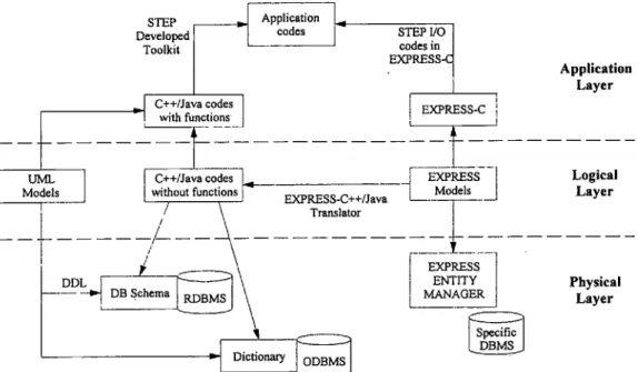
and reusable. The conventional means ofestablishing
aSTEP-based system is to use EXPRESS
language
to model thecon-ceptual
models, and then construct theapplication
layer by
object-oriented
and EXPRESS-Clanguages
asdepicted
inFigure
2. Theconceptual
data models are translated into anRDBMS (Relational DataBase
Management
System),
merged
into an ODBMS(Object-oriented
DataBaseMan-agement
System),
ormanaged by
an EXPRESS modelman-agement
system, to construct thephysical layer
of thesys-tem.
1.2 The
Physical
Layer
The
physical
layer
inFigure 2
contains the kernel database and network communication media structure. The ODBMS1
Author to whom correspondence should be addressed.
© 2000 SAGE Publications. All rights reserved. Not for commercial use or unauthorized distribution.
at NATIONAL TAIWAN UNIV LIB on August 25, 2008
http://cer.sagepub.com
Figure 1. STEP-based product data representation.
provides
better storage of information within the STEP-based system than theobject-oriented conceptual
data mod-els because the latter affects the construction of the database schema. Best results can be obtainedby
emptoying
theRDBMS after
object-oriented modeling
because it iscom-patible
with relational databases and it willguarantee
the ef-fectiveness of thelegacy
systems data retrieval. Thecom-plexity
of the information to be stored iskey
tochoosing
between the ODBMS or the RDBMS as the former is suitable
four
complexly
related data, such as the PDM and CAD/CAMsystem, while the latter is suitable for
large quantities
of data.The main concern that must be addressed when
adopting
RDBMS as the kernel of STEP-based system is theintegra-tion
of legacy
data. It is best achievedby
ODBC(Open
Data-BaseConnectivity)
because it canincorporate legacy
databy
merging
the schemaof legacy
data into the STEP-basedsys-tem
[ 12 J.
On the otherhand,
if the ODBC driver of anODBMS is used. the data
residing
on ODBMS can also beshared
by
the RDBMS.The
physical layer
of the STEP-based PDMS should beequipped
with a dataexchange,
an external shareddatabase,
or a distributed database method to secureproduct
dataexchange
andsharing.
The dataexchange
method enablesproduct
data within a PDMS to beexchanged
asphysical
files
expressed
in aplain
text[ 13].
This methodeasily
fa-cilitatessetting specifications, conducting
tests and diversesystem
applications.
Theexternally
shared database methodaccesses a common database between
companies
on acontract basis. Data are
copied
from the PDMS of thecompa-nies into the common database. The distributed data-base method distributes the
product
data among the PDMS ofcompanies
that canconcurrently
share access[
1-~-16].
Thevirtually
shared database method may be theulti-mate in
product
datasharing
intended to create a concurrentworking
environment becausealthough
the data arephysi-cally
shared on internet network, the database functions as asingle
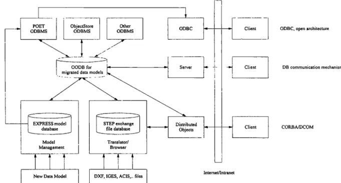
unit.The construction of a STEP-based distributed database
management system is illustrated in
Figure
3. The left side indicates thegeneration
of the internalrepresentation
of EX-PRESS codes, such as themigrated
data models in Section 2.This can be used to construct the
database, generate
parser codes, andimplement
C++ codes. The C++ codes arecom-piled
by
an ODBMS to add the management functions intooriginal
C++ codes. At the same time, a schemadictionary
Figure 2. Approach for establishing a STEP-based system.
© 2000 SAGE Publications. All rights reserved. Not for commercial use or unauthorized distribution.
at NATIONAL TAIWAN UNIV LIB on August 25, 2008
http://cer.sagepub.com
52
Figure 3. Approach for constructing STEP-based distributed management system.
and its related codes are
generated
andmanaged by
theODBMS. The shared database environment is achieved with the ODBC driver
provided
by
ODBMS[ 17,18].
Figure
4presents
three mechanisms of network communi-cation,including
an ODBC mechanism, a databasecommu-nication mechanism, and a CORBA/COM mechanism, with
their
operation
methods, that can all work within aSTEP-based PDMS. The ODBC mechanism comhines all informa-tion from the different systems into the unified data schema. Database communication relies on the ODBMS, while the
most
popular approach
is the use o1- TCP/IPprotocol
to ad-dress the PDMS server side. The CORBA/COM mechanismallows the distributed
objects
to communicate with each dis-tribute the information of PDMS.1.3 Review of
Implementation
ofApplication Layer
The
application
layer
must connect theoperations
of thephysiral layer
to theconceptual layer.
The effectiveness of data management andcompatibility
with STEP arealways
opposite,
because theimplementation
of STEP-basedsys-tem
using
ARM or AIM indicates two differentapproaches
119].
Popular
database preprocessor toolsgradually
solveFigure 4. Three mechanisms of network communication.
© 2000 SAGE Publications. All rights reserved. Not for commercial use or unauthorized distribution.
at NATIONAL TAIWAN UNIV LIB on August 25, 2008
http://cer.sagepub.com
this
phenomenon,
so thatprototyping applications
can ber-~rpidly
developed
andeasily
connected to the target data-base. Theapplication
orpresentation layer
is formedby
ref-erencing
models in theconceptual layer
to meet diversere-quirements.
A flexiblemodeling
and better communication interface are themajor
issues for a STEP-based PDMS.They
should be considered to
adopt
differentrequirements
from distinct ventures. Itemphasizes
how toflexibly synchronize
the
conceptual
models and the data structure and how toes-tahlish a network communication interface. Communication
interfacing
isimportant
for a distributed PDMS to meet the need ofmanaging
andsharing
information. Since the STEP-based system is anobject-oriented
system, most communica-tion interface relies on Java,CORBA,
or DCOM to achieve the distributed environment.STEP utilizes SDAI to
integrate
the systemby sharing
the AIMproduct
data of information systems such as CADsys-tem, PDMS, etc.
~?0,? 1 ~.
The SDAI can beregarded
as anAPI
(Application Programming
Interface) to store and share theproduct
dataindependent
of thesystem’s physical layer.
The SDAI should not be usedduring
thepractical
utilization stage since it ismerely
an interface tooperate
the database of EXPRESSlanguage.
The STEP-based data based on theap-plication
object
level ismanaged
by
using
HLDAI(High
Level Data Access Interface) that is auser-friendly
interfacewith an
application
view. A STEPengineer
can access the STEP database without an SDAI or AIMby
using
theHLDAI
(High
Level Data AccessInterface).
A STEPengi-neer shall construct the STEP data
exchange
systemaccord-ing
to its kernel data schema that is a data structure definition of informationsystems.
2.
System
ArchitectureThe bolder lines in
Figure 2
indicate themethodology
ap-plied
todevelop
the STEP-basedrepository
system in this paper. Theintegrated product
data models in STEP arecre-ated
by
a UMLmodeling
tool that generatesprogrammable
C++ codes and is translated into an
object-oriented
database,POET. The
generated
C++ codes are used todevelop
theap-plications
in thepresentation
layer,
while theobject-oriented
database isready
forstoring
the instances of the data models.Any
change
in theconceptual
models willimmediately
after the data models in thephysical
layer.
An 00 management mechanism, such as an OODBMS or serializationmecha-nism of
object-oriented
language,
is used todevelop
STEP-based PDMS toaccomplish
the management of STEP-basedinformation,
rather thanusing
SDAI or HLDAI.A STEP-based
product
datarepository
isdeveloped
to ful-fill therequirements
ofproduct
datamanagement,
exchange,.
andsharing.
Theproduct
information models followISO-10303,
STEP standard, while dataexchange, sharing,
and managementmethodology
follow themethodologies
de-fined in STEP. Therepository
canexchange
product
data and manage the CAD models and technical information asil-lustrated
inFigure
5. The functional components include anInternet-based
exchange
subsystem,
applications,
utilities, and arepository
database with an accessapparatus.
Defining
theproduct
data modelsusing
STEP standard-izcs the informationrepresentation
to assure theimplemen-tation of information
sharing.
The STEP filesexport/import
functions in thesystem
can be used togenerate
theexchange
files. Theaccompanying
utilities andapplications
can beused to demonstrate the
integration
andmanagement
capa-bility
of STEP-basedrepository.
The hest
possible
model of the STEPsystem
must becre-ated herein since the
quality
of the models affects theimple-mentation of the
system.
A subset data models based onAP2 14 is used as the kernel information models of the
infor-mation within the
development
andmanufacturing
stages
in thetarget
industry
[22],
This section describes thedevelop-ment of each task,
including modeling
the information mold-els,developing
kernel database,developing
theapplications,
anddeveloping
the utilities. Thefunctionality
andimple-mentation
methodologies
used in thepilot
system aredis-cussed in detail.
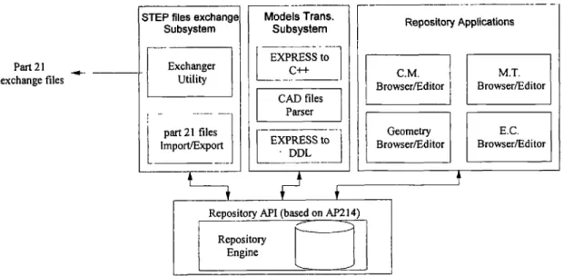
2.1 Overall
System
ArchitectureThe
repository
system should have thefollowing
compo-nents to manage
product
informationeffectively,
database management system with database interface,repository
sys-tem with access interface, utilities, and
applications,
asillus-trated in
Figure
6.The database interface
provides
theregistration
function, themanipulating
functions ofapplication
interfaces and meta-data, and themanaging
functions of user informationand database
engine.
Therepository
interfaceprovides
thevaulting, formatting,
andbrowsing
functions of allexecuting
threads. The utilities,including
system
administration and functions management,provide
and maintain information infrastructure andoperations.
The userregistration,
manage-ment, and verification are alsusupported
by
the utilities. Theapplications
provide
the end-user with aworking
interface tofulfill their
requirements.
Theimported
andexported
infor-mation follows the subset data models of AP214 in STEP1231.
The information i*eti-leB-zil andexchange
of theapplica-tions in the system,
including product
information and CAD models, follows ISO-10303 Part 20 serials like Parts 2 and 22.2.2
Modeling
the Information ModelsThe
conceptual
data models of therepository
system mustbe modeled to define the data schema. The models include AAM, ARM, AIM, and other models with
specific
program-ming language.
AAM is used to model theactivity
models withindesign
andmanufacturing
stages
while the dataman-aged
within theactivity
is modeled in ARM. ARM is thenmapped
onto the standardized data models in STEP. AIM is then translated into the models in C++ forimplementation
by
the
object-oriented language.
© 2000 SAGE Publications. All rights reserved. Not for commercial use or unauthorized distribution.
at NATIONAL TAIWAN UNIV LIB on August 25, 2008
http://cer.sagepub.com
54
© 2000 SAGE Publications. All rights reserved. Not for commercial use or unauthorized distribution.
at NATIONAL TAIWAN UNIV LIB on August 25, 2008
http://cer.sagepub.com
2.2.1
MODELING
CONCEPTUAL DATAMODELS
The
conceptual
data models of therepository
system in-ctude AAM, ARM, and AIM. Allconceptual
data Illodelv of the tablcs and CAD models in thcpilot
system arerepre-sented
using
EXPRESSlanguage
and illustratedby
EX-PRESS-G.
Thcaphlicatiun objects
of CAD models and theten sets ot~ technical information,
including engineering
re-)ated documents, material,
specification. expressed
with EX-PRESS models are defined andrepresented by
EXPRESS-G notation. The context of theconceptual
data models can be classified as the information models of CAD models and technical documents. The data models of CAD models in AIM follow AP?()3 in STEP, white the ones in the technical documents follow AP?()3, ? 1-t. and Part -t() serials parts. The AAMcaptures
the process information models in thedesign
andmanufacturing
stages. AAM utiliies IDEFOmodeling
nWhuUolo~~y.
The ARMemploys
thc’ data modes in the ven-turc. and EXPRESSlanguage
to model the information. The AIM. clcrivedhv mapping
ARM with STEP standard,reprc-,ent; STEP-based standardised
industry
data models in this paper.2.2.2 MIGRATE DATA MODELS FOR TECHNICAL INFORMATION AND CAD MODELS
Thc CAD geometry information mode) represents the
product-oriented
data structure wpresented
inFigure
I . The technical information, orproduct-oriented
data structure, isrepresented by
miscellaneous industrial table sheets. An item view is used to combine the technical information w ith the CAD models so one can track the informationthrough
the entireentity.
With this mechanism, we can reduce dataex-change, reformatting,
data management,design history,
doc-ument barriers
I ~41
whileimplementing
concurrentengi-ncerin~~.
2.2.3 IMPLEMENTATION MODELS
All
implementation
models used to define the data models of therepository
and theapplications
follows UML forOOA and OOD of theapplications.
The Data Mudels (I.E. Static Modets) andSequence
Muclels ( I.E.Dynamic
Modeb) of thcapplications
are used to manage the data structure andoper-ating
procedures.
Since theconceptual
data modelsof
prod-uct information are
specified
by
EXPRESSlanguage
and EXPRESS-Ggraphical
notation, the EXPRESSlanguage
is translated into C++ format tor use as thc reference models for the data schema of therepository
system.2.3
Developing
DatabaseThe database interface of the
repository
system manages thc databaseaccording
toconceptual
models. The informa-tiontechnology
will not be restrictedby specified
methods since theapplications
arc notdirectly
connected to a database Illanagementsystem.
Thcrelationship
of allobjects
with alist of functions and attributes of classes can be obtained
us-ing
UMLmodeling language
tospecify
the API. The API oCthe
repository
comes from the database API. which isspeci-t’icd
by
UML. EXPRESS-C models andIDL (Interface
Defi-nitionLanguage)
can also be used to handleobjects
within the CORBA architecture. Theapplications
of therepository
system useconceptual
models to access the information stored in the databasethrough
a set of interfaces. Theappli-cation interfaces can he from the lowest level API, which is the kernel
application
interface, to thehighest
levelAPI,
which is theapplication-oriented
API. Theapplication-ori-ented API can use the information models to map the
corre-sponding
instance to findthe necessary
information. The API can he classified into four kinds of API: Kernel AP1.Dictionary
API, Classification API. andObject
API. The relational database management system is usedby
therepository
system as the kernel database. A DDL(Data
De-scription Language)
isgenerated
and used to setup the table schema and data schema of the RDBMS. Theapplications
can access information of the tablc; or CAD models
through
the RDBMS. With the EXPRESS-tl)-DDL translator. the EXPRESSlanguage
can be translatcd into thecorresponding
DDL. The definition andrelationship
betweenobjects
can bemapped
into thecorresponding
data schema. Therefore, thegenerated
DDL can be used to get the definition andrelation-ship
of theobject-oriented
models in the RDBMS.The database access
operations
of theapplications
use theODBC
Bridge
of the RDBMS to communicate with the data-base. These accessoperations
encapsulWe corresponding
SQL
statements. Forexample,
the &dquo;Add New&dquo;operation
will Iencapsulate
thc INSERT statementof SQL.
while the &dquo;Edit&dquo;operations
willencapsulate
the UPDATE statementof SQL.
All of these
operations
will bepackaged
as a set of API. ODBC is used as the standard access interface of databaseto
amalgamate
with other RDBMS. Theapplications
Litilize the ODBCBridge
of the RDBMS to sendSQL
statement toeasily
access theobject
information of the databasethrough
ODBC interface. Theapplications
can use the same API toaccess data from distinct database to
amalgamate
different RDBMS. even ODBMS with an ODBCbridge.
2.4
Developing Applications
The
configuration
management,engineering
dataman-agement. geometry, and
ordering applications
are alldevel-oped according
to the AAM models advanced herein. Theconfiguration
managementapplication
can be used toman-age the
product configuration
data of therepository.
Thecontent of the
con figuration
data consists of theproduct
defi-nition as Wc’ll Wengineering change
request,suggestion,
andengineering change
issue. Theengineering
dataapplications
can be used to manage the
repository’s engineering
data, such as material management and testreport.
Thegeometry
application
is used todisplay
and render the 3D CAD model of theproduct,
while theordering application
can he used tomanage the data from the
purchase
department.
The
upplications
use kernel APIencapsulating
theSQL
of the database to access the kernel database. The API ot’there-© 2000 SAGE Publications. All rights reserved. Not for commercial use or unauthorized distribution.
at NATIONAL TAIWAN UNIV LIB on August 25, 2008
http://cer.sagepub.com
56
Figure 7. Functionality of the repository system.
pository
accesses the kernel database because the API ispackaged
as the API of therepository.
Theexport/import
subsystem
translates information from/to therepository
witha STEP-based
approach.
Thesubsystem
can be a stand-aloneapplication
or a module of anapplication.
It can be classifiedas an
export/import subsystem
or a CAD roodelexport/im-port
subsystem dcpending
on its function. Themajor
func-tionality
of thesubsystem
istranslating
the information of the tables or CAD models to and frompart 21
formats.The browser and editor are the fundamental
function-alities for each
application
of therepository
system, aa illus-trated inFigure
7. Theapplication
instances of thephysical
objects
and therelationship
between theseobjects
aredis-played
with different views. The structural browser andedi-tor divide the
graphical
user interface into twopartitions:
arapid display
of the information items on the left, and the content of the item selected on theright.
Different form views with proper controls should be used todisplay
its in-formation for distinctapplications
of the tables. A browser for CAD models is also animportant
issue forapplication.
A browser for AP203 CC6 isdeveloped
to solve the inconsis-tency for STEP 1 iles of distinct CAD systems. Anintegrating
system is alsodeveloped
to move the information from theCAD
systems
and therepository
system. 2.5 UtilitiesThe system
administration,
application
management, andauxiliary
tool utilities can be used tohelp develop
and main-tain all information in therepository
system.
Themajor
func-tions include:1. To
generate
and manage theproduct
data models of therepository
system2. To generate and manage the data schema in the
repository
system3. To record the user’s information for
managing
the user’sprivilege
4. To translate information from and to proper format, such
as EXPRESS to C++ codes, and translation between CAD systems
The
exchange
utility
isdeveloped
in Java to secure usage across distinctplatforms
between industries to transferpart
2 1-iles. Theexchanger
can monitor the progress of files andexamine the
completeness
of theexchange
files. It can beused in either server or client modes for
switching
the roles forapplication requirement.
The transaction information could also be saved to trace the user’slogin.
The translators used in thispaper adopt
one of the UG and CATIAsystems
toavoid the information loss.
3.
Implementation
The
repository
system
is tested in twomanufacturing
in-dustries.industry
A andindustry
B, toverify
thesystem
ar-chitecture.
Industry
A has the entirerepository
system, whileindustry
B, the first-tieredsupplier
ofindustry
A,
has just
theapplications
andexchanger.
Theprocedures
are discussedseparately
because theprocessing
of tables and CAD modelsare not the same.
’rhe CAD translators used for the test are UG and CATIA
translators, which are the
major
CAD systems used in the twoindustries. The
operating
system used forthe UG translator is Microsoft NT 4.0, while the one used for the CATIAtransla-tor is the IBM RS6000 UNIX. Both of these CAD translators
can translate the native CAD models into standard formats
based on AP203 and AP214. The translators for AP203 and IGES 5.3 of the two CAD systems are used to translate solid and surface CAD models to
verify
the CAD models transla-tionby
STEP and IGES. Theexchanger
utility
runs on both© 2000 SAGE Publications. All rights reserved. Not for commercial use or unauthorized distribution.
at NATIONAL TAIWAN UNIV LIB on August 25, 2008
http://cer.sagepub.com
PC Windows NT 4.0 and IBM RS6000 UNIX environments because of the
system
environments of the industries. Theapplication
scenario is theco-design
situation between thesetwo
industries.
Industry
Aemploys
aconceptual design
orengineering
change
case, and then transfer relatedinfoma-tion.
including
CAD models and related technical informa-tion. toindustry
B.Industry
B evaluates theconceptual
de-sign
orengineering change
and then transfers theirdesigns
orsuggestions
for that case. The same process isrepeated
as thefinal
design
isapproved
and themanufacturing
andordering
information is readied forproduction.
The screendumps
forthe
developed repository
systems
andexchanger
areillus-trated in
Figure
8. 3.1 Scenario 1Industry
A translates theengineering
data and CAD mod-els of aproduct
and then sends them toindustry
B.Applica-tion A includes
configuration
management,
engineering
data,
geometry,
andordering applications
as illustrated inFigure
9. Eachapplication
has itscorresponding conceptual
data modelsusing
EXPRESS,
formedby
a serial of processfrom AAM to
implementable
models in Section 2.2. The fi-nal models are translated and built into the Oracle databasesof the
repository
system.
The databases utilize the datastruc-ture, schema, and definition of the
migrated
data models toassure data
consistency.
Theapplications
of therepository
can then be
developed
based on these databases.Geometry
information is included in theproduct
informa-tion, since theproduct
information is linked andmanaged by
PDMS. Thepart 21
files of the CAD models aregenerated
from the translator of UG and CATIA. The
part
21 files inin-dustry
A aregenerated by
the translator of the UGSystem.
A STEP CAD model viewer for AP203 isdeveloped
to render the 3D models to browse the CAD models in part 21 formats. Thepart
21 files areparsed
and stored in thecorresponding
tables of the databases in
repository
to store thegeometry
in-formation inpart
21 tiles. Both of theseoperations
aresup-Figure 8. Screen dumps for the developed repository system.
© 2000 SAGE Publications. All rights reserved. Not for commercial use or unauthorized distribution.
at NATIONAL TAIWAN UNIV LIB on August 25, 2008
http://cer.sagepub.com
58
Figure 9. Working process of the applications of the repository system.
ported
inapplication
A since the source of thegeometry
in-formation can be
part ?
1 files in thedirectory
of the disk ordatabases in the
repository.
3.2 Scenario 2Industry
B receives theengineering
data and CAD models of aproduct,
and then sends back thedesign
informationaf-ter
design
orredesign. Application
B consists of theconfigu-ration management,
engineering
data, geometry, andorder-ing applications
ofindustry
B, as illustrated inFigure
9.Although
industry
B has no datarepository,
the informationexchange
andmanagement
can also beaccomplished by
us-ing
part 21exchange
files.Application
Bimports
andex-ports the
part 21
files of theengineering
data and CAD mod-els fromindustry
A. Since theconceptual
data models of each table arepre-knmvn
to these ten sets ofapplications,
thedata from
application
A can be received andinterpreted by
application
Bdirectly by mapping
the samemigrated
mod-els. Thisprocedure
is alsoapplied
to the dataexchange
of CAD models fromapplication
A.New
part ?
1 files of the CAD models from the CATIAsys-tem are
generated
and thenpassed
toindustry
Athrough
theexchanger
after theredesign
orengineering change
of the CAD files. The STEP viewer is used to browse thepart 21
I files of the CAD models inapplication
A as in scenario l. Thepart ?
1 files of the CAD models aregenerated by
the translator of CATIAsystem.
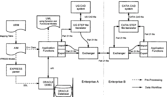
4. Conclusion
Product data
exchange
andsharing
mechanism can beac-complished
based on therepository
system.Figure
10illus-Figure
10. Product data exchange and sharing mechanisms for STEP-based repositorysystem. © 2000 SAGE Publications. All rights reserved. Not for commercial use or unauthorized distribution.
at NATIONAL TAIWAN UNIV LIB on August 25, 2008
http://cer.sagepub.com
trates the summary
of applicable methodology
of the STEP-basedrepository
system. R 1 and R2 are the full set of there-pository
system,
while A I and A2 represent theapplication
of therepository
system without arepository
database. The dataexchange
andsharing
scenarios can be R-R,R-A,
orA-A. The data
exchange
andsharing
mechanism are listed inFigure
I ():part 2).
SDAI withaccessing
databasefunctional-ity,
ODBC,accessing
API of DBMS, COM or CORBA. Themechanism
using
part
21 relies on thequality
andflexibility
ofimport/export
functional module to assure thequality
ofthe data
exchange
andsharing.
The mechanismusing
SDAI relies on theflexibility
of information modelsmanagement
and translation to assure the
quality
of the dataexchange
andsharing.
The mechanism thatemploys
ODBC relies on the translation andconsistency
of information models from theobject-oriented
data structure and relational data structure toassure the
quality
of the dataexchange
andsharing.
Themechanism that
manipulates
the API of DBMS relies on theflexibility
of information models management and transla-tion. The mechanismusing
COM or CORBA relies on thedevelopment
of services on distributed environment to as-sure thequality
of the dataexchange
andsharing.
Thesemechanisms co-exist to
accomplish
the dataexchange
andsharing
between and within industries.The data
repository
developed
herein is used to setup the management system for technical document and CAD mod-els. The informationexchange
andsharing
is easy to processbecause the information
representation
and management is based on standardizedproduct
data models. The interna-tional standard, STEP, secures theimplementation
andex-tensibility
of therepository
system. The systemintegration
of miscellaneous systems, such as MRP, MRPII, PDMS, ERP, can be ensured with the standardized data models. The sameapplication
will be extended to other areas of themanu-facturing
industries toorganize
their virtualenterprise
envi-ronment and promote their
productivity.
References1. K. Hodota, "Product and information
life-cycle
withproduct
configuration
database system on Internet," in 21stCentury
Commerce & CALS EXPO International
Conference
’97, 1997.2. A.
McKay,
F. Erens, and M. S. Bloor,"Relating product
defi-nition andproduct
variety,"
Research inEngineering Design,
vol. 2, pp. 63-80, 1996.
3. O. A. Suarez, J. L. A. Foronda, and F. M. Abreu, "Standard based framework for the
development
ofmanufacturing
con-trol
system,"
International Journalof Computer Integrated
Manufacturing
System,
vol.11,
pp.401-415,
1998.4. J. K. Wu, T. H. Liu, and G. W. Fischer, "An
integrated
PDES/STEP based information model for CAE and CAMap-plications,"
in The Second InternationalConference
onAuto-mation
Technology,
1992, pp. 179-187.5. Y. M. Chen and Y. T. Hsiao, "A collaborative data
manage-ment framework for concurrent
product
and processdevelop-ment," International Journal
of Computer
Integrated
Manu-facturing System,
vol. 10, pp.446-469, 1997.
6. R. Jordim-Goncalves et al.,
"Implementation
of computerinte-grated
manufacturing
systemsusing
SIP: CIM case studiesus-ing
a STEPapproach,"
International Journalof Computer
In-tegrated Manufacturing System,
vol. 10, pp.172-180,
1997. 7. Y. V. R.Reddy
et al.,"Computer
support for concurrentengi-neering," Computer,
vol. 26, pp.12-16,
1993.8. G. L. Smith and J. C.
Muller, "PreAmp—a pre-competitive
project
inintelligent manufacturing technology:
anarchitec-ture to demonstrate concurrent
engineering
and informationsharing,"
ConcurrentEngineering :
Research andApplica-tions, vol. 2, pp. 107-115, 1994.
9. F. Chaxel, E.
Bajic
and J. Richard, "Mobile databases nodes formanufacturing
information management: a STEP basedap-proach,"
The International Journalof
AdvancedManufac-turing Technology,
pp. 125-133, 1997.10. I.
Bailey,
P.Spiby,
and J.Vuoskoski,
"Pilotimplementation
of processplant lifecycle
functional dataexchange conforming
toSTEP AP-221, Part 2:
Logical
&physical
data models," ES-PRIT-IV,PIPPIN,
1997.11. P.
Spiby
and D. Sanderson, "Introduction to EXPRESS 2," ISO SC4/WG10 Document N58, June 1998.12. L.
Bernosky, "Turning legacy
data intoenterprise
informa-tion," in 21stCentury
Commerce & CALSEXPO InternationalConference
’97, 1997.13. D. An et al., "A
product
dataexchange integrated
structureus-ing
PDES/STEP for automatedmanufacturing application,"
Computers
Industry Engineering,
vol. 29, pp.711-715, 1995.
14. Y. Tanaka et al., "Product data
sharing
among distributed het-erogeneous PDMs," in CALS EXPO ’97 International, 1997. 15. S. D. Urban et al., "Aheterogeneous,
active databasearchitec-ture for
engineering
datamanagement,"
International Journalof Computer
Integrated
Manufacturing System,
vol. 7, pp. 276-293, 1994.16. S. D. Urban, J. J. Shan, and M. T.
Rogers,
"Engineering
datamanagement
archieving
integration through
databasetechnol-ogy," Computing
& ControlEngineering
Journal, pp.119-126, 1993.
17. D. L.
Spooner,
"Anobject-oriented
product
databaseusing
ROSE,"
Journalof
Intelligent
Manufacturing,
vol. 5, pp. 13-21,1994.18. S. K. Ke and S. C. Yeh, "The
pilot
system for STEP-basedproduct
dataexchange,"
in CALS/EC EXPO ’98Japan,
pp. 197-206, 1998.19. S. Rahimifard and S. T. Newman, "A
methodology
todevelop
EXPRESS data models," International Journal
of Computer
Integrated
Manufacturing System,
vol. 9, pp. 61-72, 1996. 20. R. N.Botting
and A. N. Godwin,"Analysis
of the STEPstan-dard data access interface
using
formal methods,"Computer
Standards &
Interfaces,
vol. 17, pp. 437-455, 1995.21. A. Goh et al, "A
study
of SDAIimplementation
onobject-ori-ented databases,"
Computer
Standards &Interfaces,
vol. 16,pp. 33-43, 1994.
22. H. Scheder,
"Requirements
of car manufacturers forproduct
data management in an extended
enterprise,"
STEP-Forum97,
1997.
23. ISO, 1997, ISO 10303-214 CDII—Core Data for Automotive Mechanical
Design
Processes, 1997.24. B.
Prasad,
Concurrentengineering
fundamentals, Vol. 2,Inte-grated product
development, Upper
SaddleRiver,
N.J., Prentice Hall PTR,1996-1997,
pp. 367-375.© 2000 SAGE Publications. All rights reserved. Not for commercial use or unauthorized distribution.
at NATIONAL TAIWAN UNIV LIB on August 25, 2008
http://cer.sagepub.com
60
Chun-Fong
YouChun-Fong
You,
Associate Pro-fessor in theDepartment
of Me-chanicalEngineering,
NTU, got his Master’s and Ph.Ddegrees
from Cranfield Institute ofTechnology,
UK. Hisprofessional specialties
in-clude Solid ModelSystems,
Com-putatioilal
Geometry
and theInte-gration
of CAD/CAM.Shen-Chou Yeh
Shen-Chou Yeh received his Master’s
degree
in MechanicalEn-gineering
from NSYSU. He iscur-rently
a Ph.D student at the NTUworking
in the area ofproduct
dataexchange,
sharing,
andmanage-ment
using
STEP. His researchin-terest is in the
enabling
technologies
for STEP-based informationsystem
anddeveloping
andimplementing
STEP-basedmanufacturing
indus-try standard in Taiwan.© 2000 SAGE Publications. All rights reserved. Not for commercial use or unauthorized distribution.
at NATIONAL TAIWAN UNIV LIB on August 25, 2008
http://cer.sagepub.com