國立交通大學
多媒體工程研究所
碩 士 論 文
單一影像自動化建立城市建築物場景模型之研究
Automatic modeling 3D urban scenes through a
single image
研究生 : 朱倩雯
指導教授 : 林奕成 教授
單一影像自動化建立城市建築物場景模型之研究
Automatic modeling 3D urban scenes through a single image
研 究 生:朱倩雯 Student:Chien-Wen Chu
指導教授:林奕成 Advisor:Dr. I-Chen Lin
國 立 交 通 大 學
多 媒 體 工 程 研 究 所
碩 士 論 文
A Thesis
Submitted to Institute of MultimediaEngineering College of Computer Science
National Chiao Tung University in partial Fulfillment of the Requirements
for the Degree of Master
in
Computer Science
September 2011
Hsinchu, Taiwan, Republic of China
I
單一影像自動化建立城市建築物場景模型之研
究
研究生 : 朱倩雯 指導教授 :林奕成 博士
國立交通大學
多媒體工程研究所
摘要
本論文提出一個從單一城市街景影像中自動化擷取建築物表面並重
建其影像之場景之系統。我們使用基於投票機制的影像消失點預測方法與
線段偵測與分析進一步建築物表面的透視幾何資訊,並依此作為透視修正
的影像修補方法之基礎。自動化建築物外牆表面經由四個階段做擷取 ,分
別為:前置處理階段、初步表面擷取階段、表面精製階段與前景影像修補階
段。每階段依序分析影像中提供的建築物牆面之幾何資訊,並整合後擷取
建築物的牆面範圍與其在立體空間的轉向,讓使用者可便利且快速地完成
城市街景建模。
關鍵字 : 消失點偵測,牆面擷取,基於影像之建模
II
Automatic modeling 3D urban scenes through a
single image
Student : Chien-Wen Chu Advisor : Prof. I-Chen Lin
Institute of Multimedia Engineering
National Chiao Tung University
Abstract
This paper presents an automatic method for extraction of building facades from a single street view image. These façades can be used to reconstruct a primitive 3D street scene from the image. The extraction process involves our voting- based vanishing points prediction method and automatic line segment detection. The estimated vanishing points in the image are used to group line segments. We extract individual building facades and use perspective inpainting to remove the obstacles in front of the buildings. The orientation of each building facade is automatically evaluated for 3D scene reconstruction.
III
Acknowledge
本篇論文的完成,首先我非常感謝我的父母親對我學業的全力支持與不間斷的鼓勵,讓 我可以心無顧慮地專心研究。在碩士兩年的求學生涯中,感謝林奕成教授細心的指導, 適時地指引我研究的方向,增廣了我的專業知識。最後感謝這兩年來一起做研究的實驗 室同學們,大家一起討論課業和相聚的歡樂時光豐富了我的碩士生涯。IV
Contents
摘要……….. I
Abstract………II
Acknowledge………...III
Contents...………....IV
List of Figure………V
List of Table.………...VI
Chapter 1 Introduction………..1
1.1 Motivation………1
1.2 Overview………...3
Chapter 2 Related Work……….……...6
Chapter 3 Preprocessing and Polygon Extraction………...11
3.1 Preprocessing………11
3.2 Polygon Extraction………...13
Chapter 4 Polygon Refinement and Perspective Inpainting………...20
4.1 Polygon Refinement……….20
4.2 Perspective Inpainting………..24
Chapter 5 Experiment and Result………29
Chapter 6 Conclusion and Future Work………..37
6.1 Conclusion………37
6.2 Future Work……….37
V
List of Figure
Figure 1.1 The system overview of our system
……….. 5
Figure 2.1 The Gaussian sphere
………..………….…7
Figure 2.2 3D model from a single image by [HAH05]...
………...9
Figure 3.1 Hough transform
….……….………....12
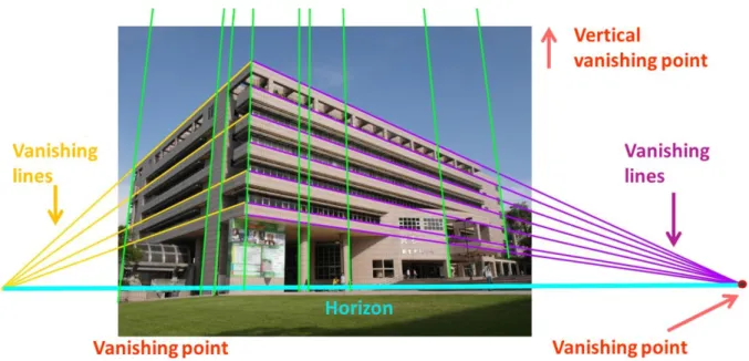
Figure 3.2 A example of vanishing points and vanishing lines
………..…...14
Figure 3.3 The orientation label of line segments in the scene and the Vertical Corner Line Hypothesis
………...17
Figure 5.1 Top: input image. Bottom : The structural feature lines extracted by Hough transform
………....29
Figure 5.2 Top Left:Left vanishing points candidates.Top Right:Right vanishing points candidates .Bottom : Middele vanishing points candidates.…
...30
Figure 5.3 GMM clustering and final bounding polygon
……….…...32
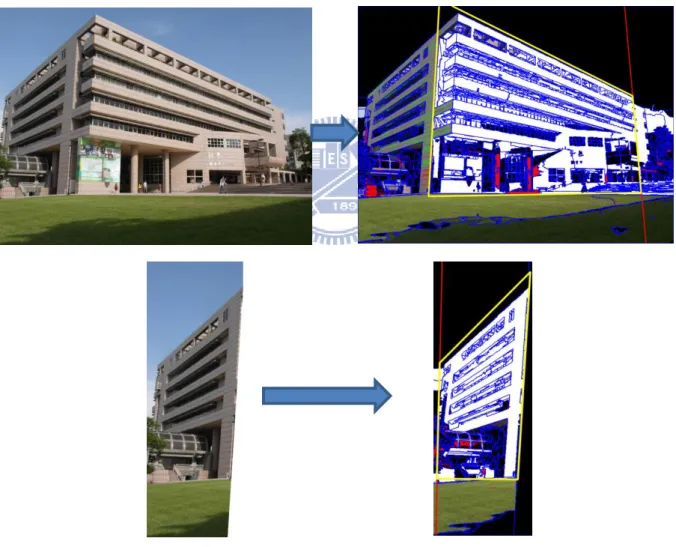
Figure 5.4 Left is the origin input image , right is the perpective inpainting results for foreground obstacle removal.
………...33
Figure 5.5 (a) is the origin input image (b) is the reconstruction 3D scene of the input. (c) (d) is the scene from different view point of the reconstructed model
……….………33
Figure 5.6 Modeling procedure.
……….…34
Figure 5.7(a) is the origin input image (b) is the reconstruction 3D scene of Input image, combining the main façade and the sub-façade of the input image. (c) (d) is the scene from different view point of the reconstructed model
……..35
Figure 5.8 (a) is the origin input image (b) is the reconstruction 3D scene of Input image, combining the main façade and the sub-façade of the input image. (c) (d) is the scene from different view point of the reconstructed model
……..36
VI
List of Table
1
Chapter 1
Introduction
1.1 Motivation
When we take a picture in a city scene, the image consist of several geometric classes, such as sky, buildings, streets, people and cars. It’s trivial for human to recognize each component at a quick glance, but it’s a very challenging task for computer. We try to decompose such complex scene into rough geometric classes.
Modern computer vision techniques can help to recover many useful information about the image: find lines and contour, segment the image , detect objects and much more. However, those information only provide low-level features about the image, we are still lack of global understanding of the whole image. If we want to distinguish each component and label them into different geometric classes, we need to connect various pieces of information and develop higher-order features for reasoning about the scene and its contents.
In man-made environments, people perceive and infer the spatial relations among different objects by observing the geometric structures in the scene. Plenty of objects can provide spatial information in the urban scenes, such as roads, streets and buildings,
2
especially rectilinear architectures. The surface planes surrounding a building and structural edges of architecture can establish strong spatial relations and geometry about the scene. Therefore, exploiting the observation of the architecture can help us to extract more cues in the urban environment.
In this thesis, we propose an automatic method for extraction of individual building facades using vanishing points prediction. We use the vanishing points in the image to guide the extraction process. The vanishing points are obtained from our voting-based vanishing points prediction method , which has stable results from a single image. Our approach utilizes the strong feature lines in architecture and their relation with the vanishing points in the image. Either horizontal or vertical lines of architectures describe reliable information of 3D scene orientation. Therefore, with the vanishing points we can accelerate the process of selecting useful information for façade extraction .
We use perspective inpainting to remove the obstacles in front of the building façades to refine the extraction result. The bounding polygon of each building façade is obtained and used as 3D spatial information to guide the perspective inpainting process. Our goal is to recognize geometric classes in the image and distinguish the building façade from obstacle regions blocking the buildings. We try to recover a simple 3D building and street model from the image, removing all the obstacle in front of buildings.
The main insight of this paper is that we evaluate vanishing points of a scene to recover the 3D orientation of architecture and extract individual buildings facades. We progressively recover structural knowledge of the image and remove unwanted objects using perspective inpainting. We present the system overview in the next chapter to explain how our framework works. In the third and the forth chapter, we elaborate our method and explain the
3
reason for choosing such methods. Finally, we demonstrate our experiments and discuss the results.
1.2 Overview
We present our system overview and explain how each part functions. We focus on outdoor architecture scenes. There are four stages in our system: Preprocessing stage, polygon extraction stage, polygon refinement stage and inpainting stage. With these stages, our approach progressively extracts building façades and refines the result. Also, we obtain their bounding polygons of each façade to guide the perspective inpainting after automatic obstacles removing.
First, in the preprocessing stage, we employ the Hough transformation to detect the features line of the buildings in the image. The result feature lines are utilized in our vanishing point prediction method. We can choose to enhance the result of Hough transformation or not in this stage.
In the polygon extraction stage, we predict vanishing points from the result of Hough transformation with a voting-based scheme, we obtain stable major vanishing points candidates. Users can manually choose desired vanishing points and remove unwanted vanishing points. After vanishing points is obtained ,we use line segment detection to detection the feature line segments in the image and group line segments according to their relation with vanishing points. Grouped line segments can be further used to refer where the vertical corner line of building is. The vertical corner line can provide extra information about where the corner of building might be and where to separate different building façades. A preliminary polygon is used to represent the approximation area of building façade and extracted by using the vanishing points and the feature lines of building.
4
regions in with pixels are similarity inside a region. In the polygon refinement stage, we use the segmentation result to find the possible sky region and remove it. Otherwise, we can use Grab cut algorithm to improve the result of removing sky region. We use the preliminary polygon information and remaining non-sky region to find more accurate building façade information. Modify the preliminary polygon into more accurate bounding polygon of the building façade .
Finally, in the inpainting stage we detect the possible obstacle regions and use the Gaussian mixture model (GMM) to classify the image to find more accurate obstacles. Then, after remove the obstacle regions the perspective inpainting method is employed to inpaint the removed regions to provide convincing street result. The perspective inpainting require a 3D orientation of the inpainted plane, which is the bounding polygon ,to guide the inpaint process.More details of perspective inpaintin will be metioned in later chapter.Figure 1.1 shows the system overview of our system.
5 Input image
Output
Builind façades and bounding polygon
Figure 1.1 The system overview of our system
Polygon Extraction stage
Polygon Refinement stage
Inpainting stage
Preprocessing stage
Hough Transform Vanishing Points Prediction Line Segment Detection Extract preliminary Polygon Image SegmentationSky Region Detection and Removal Foreground Obstacle Removal Perspectve Inpainting Polygon Trimming and 3D Scene Reconstruction
6
Chapter 2
Related Work
This thesis relates to vanishing point estimation and image-based rendering methods. The problem of vanishing point estimation has been extensively studied in the past decades. There are a number of approaches that detect vanishing point in different contexts and for various applications. Modeling 3D architectural units from the urban images attracts more and more attention in recent years. Thus later in this chapter we will introduce the previous works related to both fields.
The importance and usefulness of vanishing point extraction has been demonstrated in various fields. Vanishing point detection is widely exploited in the field of robotic navigation , road detection [KAP09] , calibration of camera [CAP 90] , pose estimation [KZ02] and 3D scene reconstruction [SKF06 ,SSS08]. The vanishing points estimation methods can be roughly divided into two categories. The first category requires prior information about the internal parameters of camera and based on certain assumptions. The other category does not need priori information and can operate in an uncalibrated environment.
In the first category, one of the most commonly used methods is the Gaussian Sphere. Originally, Barnard developed the Gaussian Sphere method in 1983 [Barn 83]. The Gaussian
7
Sphere is a unit sphere used for representation where the centers of the Gaussian Sphere is located on the optical center of the camera. As shown in Figure 2.1, a line segment in the image can be represented as a circle on the Gaussian sphere and a point on the Gaussian sphere corresponds to a vanishing point in the image.This approach enhanced in the later work by Almansa et al. [ADV03]. The authors proposed a method for vanishing points detection that combines Gaussian sphere and Hough transform.
Figure 2.1 The Gaussian sphere
In more recently techniques by Coughlan and Yuille [COU 99] [COU03], the authors introduced a Bayesian approach to edge grouping under the Manhattan assumptions that support the existence of three mutually orthogonal vanishing directions in the scene. Under this assumption, the expectation maximization (EM) method is later proposed in [SD04] to estimate the vanishing directions. The method considered the intensity gradients of the pixel unit in the image and searched over the continuous parameters that affect the location of vanishing points in a scene and optimize over multiple groups of orthogonal vanishing directions. Those algorithms above require the knowledge of internal parameters.
8
The other category does not assume knowledge of internal parameters or any priori assumption. Most vanishing point detection methods require edge grouping to further deduce vanishing directions. Košecká et al. [KZ02] extended the work of Antone and Teller [ANT00] and employ vanishing points estimation in uncalibrated setting have been successfully demonstrated. Aguilera et al. [ALC05] suggested an approach which combines RANSAC and Gaussian sphere method to detect vanishing points and vanishing directions. Rother [ROT02] proposed a method to obtain camera geometry by deducing from vanishing points of three orthogonal directions and rejecting falsely detected vanishing points. However, most of the previous techniques in determining the vanishing point in single image or multiple images requires prior information and were computationally expensive.
Our vanishing point detection method estimates the vanishing points by exploiting the dominant structure features in the scene. In man-made environments, the majority of structure lines will align with the orthogonal vanishing directions. Thus we utilize this observation to estimate and detect vanishing points , which can further provide valid geometry constrain of the building façade and its orientation information. Our approach is efficient to implement and needs no camera calibration information to assist the estimation process.
Modeling 3D architectural units from the urban images attracts more and more attention in recent years. In image-based modeling, image parsing and building façade extraction are crucial. Müller et al. [MZW07] took a single façade image as input image to automatically compute a 3D geometric model. Their algorithm performs a procedural modeling pipeline to top-down subdivides a façade texture into elements and use image analysis to make correspond with the input image. Most of the existing image-based modeling methods require multiple views as the input images. Xiao et al. [XFZ09] proposed an automatic approach to generate street-side 3D models from images captured along the streets
9
at ground level. They utilize the strong priors of building regularity to develop multi-view semantic segmentation method and labeling each area with a specific object class. A partition scheme is then introduced to separate buildings into independent blocks using the major line structures of the scene. Zhao. et al.[ZFX10] utilized a sequence of images as input and parse the environment into building ,the ground and the sky by fitting the 3D point cloud to the building plane and ground plane with RANSAC method. They develop a dynamic programming algorithm to optimization the separation of the building region into individual façades.
Other approaches exploit the information from a single image to recover the 3d structure in the scene. Hoiem et al. [HAH05] demonstrated an automatic method for creating a 3D model from a single image. The authors utilize the idea of pop-up book to construct simple model. The system recovered the geometric classes of the scene by defining their orientations labels each region of an outdoor image as ground, vertical, or sky. Line segments fitted to the ground-vertical boundary in the image and an estimate of the horizon's position provide the necessary information to determine where to "cut" and "fold" in the image. The model is then popped up, and the image is texture mapped onto the model. As shown in Figure 2.2
Figure 2.2 3D model from a single image by [HAH05]
Figure 2.2 Left : original input image ; Right : views from an automatically generated 3D model
10
Our system requires a single urban image as input. We don’t require a sequence of input images to obtain 3D point cloud and reconstruct the building shape and fitting plane. Our method takes a pure 2D approach to estimate the perspective in the scene and the orientation of building façades by using estimated vanishing points. Our system have applied to automatically remove foreground obstacle that blocks the view in front of building façades and repair the removed empty regions with perspective inpainting .We use the inpainting result of the building façade to reconstruct the scene in the input image.
11
Chapter 3
Preprocessing and Polygon Extraction
In the preprocessing stage, the Hough transformation [DOH72] is employed to extract the feature lines of architectures in input images. Users can choose whether they would like to enhance the Hough transform procedure. Next, in the polygon extraction stage, we apply our voting-based vanishing point prediction method to estimate the vanishing points. Our prediction method finds a set of locations (pixels), called vanishing point candidates, which have high probabilities to be vanishing points in the input image. The vanishing point candidates are obtained with the highest voting scores in our predicting model. Users can manually specify the desired number of candidates and remove unwanted candidates. Once vanishing points are obtained from the input image, they offer valid information in the later polygon extraction process.
3.1 Preprocessing
Hough transform
First we use the Canny edge detection [CAN86] to obtain image pixels on the edges of the buildings. We want to group the extracted edge features to a set of straight lines. Thus, we apply the Hough transform on the edge pixels to obtain the main feature lines in the buildings.
12
In computer vision, the Hough transform is a voting procedure used to extract features from an input image by a voting procedure. It transforms the input image to an accumulator space and carries out voting procedure in the accumulator space. The Hough transform are commonly used to detect straight lines and arbitrary shapes in images, such as circles or ellipses. Here we utilize its ability to extract lines in an image.
In the Hough transform, a line in the image space can be represented as a point in the accumulator space. In the image space, the straight line can be described as y = mx + b .m stands for the slope parameter and b is the intercept parameter. For a line in the Hough transform, the line is denoted as a point in the accumulator space. As shown in Figure 3.1.γ is the length of a normal from the origin to the line and is the orientation of with respect to the X-axis. A point passed by different lines in image space can be mapped onto several points in accumulator space. If two points in the image space are passed by a line, they will pass through a common point in accumulator space. The voting procedure is then carried out to find the most intersected points in the accumulator space, indicating the main common lines that pass through the largest quantity of points in the input image.
(a)
(a) (b) (c) Figure 3.1 Hough transform (a) The normal parameters for a line
(b) Projection of collinear points onto lines (c) All possible lines in the accumulator space
13
Here we use Hough transform to detect the main feature lines of the buildings. Parallel lines are common in architectural scenes containing man-made structures. Thus, the feature lines become an important and major feature to describe geometry of the architecture. We assume that rectangular buildings are built on the ground, and the façades of the buildings are perpendicular to the ground plane. The parallel lines on the same building façade will converge at the vanishing point in an image after perspective projection. Therefore, the feature lines of a building are most likely in correspondence with the vanishing lines and intersect in the vanishing points.
Enhancement for Hough transform
We make use of the Harris corner detection [HAR88] to optionally enhance the Hough transform result. Since the detected corner points in the image are mostly to lie on the edges of the buildings, emphasizing corner points will enhance the weight of collinear points on the edge of building in Hough transformation. Thus the enhance method results in better and strong main structure lines in the buildings after Hough transformation.
3.2 Polygon Extraction
Vanishing points prediction
Local image features have been shown to be a powerful tool for further inference of the context in an image, such as vanishing points and vanishing lines. Under perspective projection, parallel lines in 3D world appear to converge at a point in the image called
14
Figure 3.2 A example of vanishing points and vanishing lines
lines (VL). We assume that there are several horizontal vanishing points in the scene. Since we assume that the vertical structure lines of the architecture are perpendicular to the ground plane, only one vertical vanishing point exists in the scene. The horizontal vanishing lines converge at horizontal vanishing points and the vertical vanishing lines intersect at the vertical vanishing point. The example of vanishing points and vanishing direction is shown in Figure 3.2.
Since the main structural feature lines of the building are likely in correspondence with the vanishing lines, we can utilize this character to find vanishing points in the image. (See Figure 3.2.)To estimate the possible location where the vanishing points are, a voting-based prediction method is adopted as well. First, we divide the feature lines detected by Hough transform into horizontal line group and vertical line group according to their orientation. Then, we utilize these two line groups of structure features to estimate the horizontal vanishing points and the vertical vanishing point.
15
We formulate a probability model for predicting the potential location vp as a vanishing point in the image I. The objective is to learn this model from a set of possible vanishing lines from the Hough transform. The feature lines extracted by the Hough transform are used to subsequently cast probabilistic votes for possible vanishing point locations, where the hypothesis score is obtained as a sum over all votes. We define a score function V of the voting procedure as a probability density over the vanishing points location vp = (x, y) in the image I :
| ∑ | (3-1)
where FL is a set of features lines . | is a functions specifies if a feature line f is found in the image I, which then votes for the vanishing point location vp by | .
Table 3.1 Vanishing point prediction scheme VANISHING POINT PREDICTION SCHEME
1. Extract main structural feature lines of architecture by Hough transformation.
2. Structural feature lines cast probabilistic votes for possible vanishing point locations by sum over score function of each lines.
3. Pixel x on feature lines votes using a single asymmetric Gaussian kernel to propagate weight effect around x .
4. Apply local minimum suppression on the predicted probability model in the voting space.
5. Search for a strong vanishing point candidate with local maximum score in a region.
6. Select the N vanishing point candidates with top score in the model,
16
We compute the voting score of every point that feature line passes through :
| ∑ | (3-2)
x is the point on the feature line f. We propagate the voting effect around x with a single asymmetric Gaussian kernel.
By analyzing this voting space, we can identify the peaks to find possible vanishing point candidates. The number of vanishing point candidates can be manual assign. Non-maximum suppression is used to find a strong vanishing point candidate with local maximum score in a region. The vanishing point prediction method is briefly described in Table I.
Our vanishing point prediction method is focus on single images. There is no 3D information about the image required, such as the camera position and camera parameters. It is not an iterative approach, thus the computation complexity is low. We employ an efficient voting procedure to find the stable vanishing points. Those vanishing point candidate found in a single image is quite stable and accurate. We can use the result to find where the main vanishing points are located and utilize it as a powerful cue in subsequent process. It takes very little user intervention for people to correctly infer the locations of vanishing points in a image. Thus, we can also optionally remove unwanted vanishing points from our vanishing point candidates to improve the result.
Line Segment Detection
17
With the main feature lines of the building and predicted vanishing points, we only have preliminary information about the architecture in the image. We still need more cues to infer the structure about the buildings. A line segment detection method [GJMR10] is employed to extract detail line segments that describe the structure of the building.
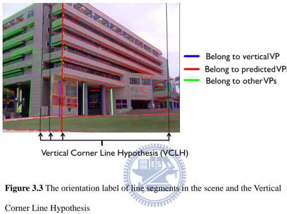
Figure 3.3 The orientation label of line segments in the scene and the Vertical Corner Line Hypothesis
We group these line segments into three groups according to their relation with the vanishing points. There are line segments vanishing at vertical vanishing point, at main vanishing points and other case. Different labels are attached to each line segment , indicating different group that it belongs. These groups of line segments are utilized to infer the Vertical
Corner Line Hypothesis (VCLH) of the building structure. A example of orientation label of
line segments in the scene and the Vertical Corner Line Hypothesis is shown in Figure 3.3.
Vertical Corner Line Hypothesis (VCLH) is a concept that inspired by the paper
“Estimating Camera Pose from a Single Urban Ground-View Omnidirectional Image and a 2D Building Outline Map” [CCTPC10]. A Vertical Corner Line Hypothesis is a line in image
18
that indicates a vertical corner edge of the buildings might be. We utilize the line segments that vanishing in accordance with vertical vanishing points to find a set of VLCH. This is done by solving a least square problem of finding a line passes some vertical collinear line segments.
Beside the vertical feature lines of building obtain by Hough transform, we also estimate extra VCLHs from two groups by using line segments with orientation labels: Group(1) Collinearity with 1 or more vertical aligned line segments and group(2) Collinearity with end points of some line segments sharing a common horizontal vanishing point.For group(1), we search for sets of line segments that have vertical orientation label and check their collinearity with each other in each line segment set. If a set of vertical line segments is over a number of threshold and collinear, we find the best-fitting line for all the endpoints in the set by least square solution. This best-fitting line is a possible VCLH in the image. For group(2), we utilize the line segments which are labeled with different horizontal orientation labels to find other possible VCLHs in the image. By checking the collinearity of the endpoints in different labeled line segments, we can find several sets of endpoint are collinear. Those collinear endpoints are used to find a best-fitting line through them and obtain possible VCLH.
Preliminary Polygon Extraction
After the vanishing point candidates are obtained, we apply those vanishing points in preliminary polygon extraction. A preliminary polygon is a region that contains approximate façades of the building, and its orientation satisfies the vanishing direction with vanishing points. The preliminary polygon is just an intermediate result of extraction process, and it still requires a refinement process to complete the final façade extraction result.
19
The vanishing point candidates are used to judge whether a feature line is a valid vanishing line according to its orientation, i.e. this line passes through the vanishing point candidates and their nearby regions. We choose the upper most and the lower most valid feature lines to be the boundary lines of the preliminary polygon. A reference vertical feature line is also selected to be the boundary line according to the position of the main vanishing points in the image.
20
Chapter 4
Polygon Refinement and Perspective
Inpainting
4.1 Polygon Refinement
After the polygon extraction procedure, our next step is to improve the extracted contour to be more precise. From our observation, we found the upper outline of the buildings and the sky is conspicuous. We can specifically detect the sky region for refinement and align the façade boundary for more detailed results.
Sky Region Detection and Removal
A mean-shift based image segmentation [COM02] is utilized to group similar pixels in the neighborhood into several regions. We employ the Edge Detection and Image Segmentation (EDISON) System from Rutgers University to implement image segmentation .To identify where the sky region are located, we first sort the image segmentation regions R
R1,R2,,RN
according to their height. Because the sky regiontends to be in the upper region, the possible sky regions are at top regions and take a certain proportion in the image. We set the half height of the image as the constraint line and the
21
regions with eighty percent pixels higher than the constraint line, Rh
r1,r2,,rk
, are selected and sorted from high to low in heights. Rh
r1,r2,,rk
are then sorted accordingto their number of pixels in the region as well. The regions from top twenty percent of R h
with sufficient pixel amount are the possible sky region, denoted asR . S
If the detected possible sky region RS presents a plausible result, i.e. it can define a satisfying boundary between the buildings and the sky region according to observation from the users, we remove it directly from image. Otherwise, we subsequently use Grab cut [RKB04] algorithm to assist the sky region detection and removal. The background information of the Grab cut algorithm is provided by pixels inside the regions fromR . In our S
sky detection and removal procedure, our approach provides stable and reliable results.
Polygon Trimming
So far we obtain low-level features and general information about the extraction target, such as the preliminary polygon with sky removal refinement, the VCLHs indicating the vertical corners of the buildings and the image segmentation. The problem is how to integrate all the scattering pieces of information into useful high-level cues to polish the result from extraction process. We combine the image segmentation result with the preliminary polygon information to refine the other outline boundaries of the buildings.
The regions which have over eighty percent pixels overlapping the preliminary polygon are extracted, called polygon regions. We denote a set of regions belonging to the polygon regions as With the help from the mean-shift based image segmentation, we can have more precise details about the boundaries between the buildings and other regions. Thus, we can get more precise and delicate outline of our building extracted façades by
22
distinguish the boundaries that separate the main part of the buildings and the other regions in the image.
The VCLHs computed from the polygon extraction stage are used to redefine the left most and right most vertical boundaries of extracted building façade. The new vertical boundaries and the old upper and lower boundaries from horizontal vanishing lines produce a new bounding polygon which contains the whole overlapped regions. The bounding polygon of the extracted building façade, , is comprised of two horizontal vanishing line sets
BL ,U BLL
and the newly updated vertical boundaries lines
BL ,L BLR
Foreground obstacle removal
Besides removing the sky region, we also want to remove the obstacle objects, which block the view of the building in the foreground, to polish the extracted building façade. Our approach first makes use of the structural information to searches for the possible obstacle regions in the scene. Most of the obstacles in the urban environment are crowds, cars, and bushes usually appear at relative low position in comparison with the buildings. Thus, we narrow down our search area in the lower-half proportion of the image. We then utilize the detected line segments with vanishing direction labels as structural information. If a region is not supported by any line segments that align with the vanishing direction, the region is considered to be possible foreground obstacle objects, denoted as . We define possible façade regions as { } . The possible façade regions are
obtained by removing the foreground obstacle objects from the polygon regions.
23
using Expectation-Maximization algorithm and further cluster foreground obstacle objects with multi-Gaussian distribution. The EM (Expectation-Maximization) algorithm is an unsupervised learning algorithm and estimates the parameters of a Gaussian mixture distribution with a specified number of mixtures. The EM algorithm is an iterative procedure and performs two steps : E(Expectation)-step and M(Maximization)-step in each iteration. Probability density function of a GMM model with m number of mixtures is shown as:
∑ ∑ (4-1) ⁄ | |⁄ { } (4-2) ∑
where is the weight of k-th mixture , is the normal distribution density with is the mean and is the covariance matrix.
We denote façade sample set as . The EM algorithm computes the maximum-likelihood estimates (MLE) of all the Gaussian mixture parameters, i.e.
,from the input sample set. The log-likelihood function of GMM is defined as: ∑ ∑ (4-3) In the E- step, with the current mixture parameter estimates we can find a probability of sample i to belong to mixture k :
∑𝑚 𝜑 𝑥 𝑎 𝜑(𝑥 𝑎 ) =
(4-4)
24 ∑ ∑ ∑ ∑ ∑ (4-5) The EM algorithm is performed until the maximum-likelihood estimates (MLE) converge.
After training a Gaussian mixture model (GMM) from input sample set ,we cluster foreground obstacle objects with the probability response value from computed GMM)using façade sample set response probability. Pixels of foreground obstacle objects are further distinguished between façade regions and obstacle objects regions using the main response probability in the GMM. If pixels from have the same response value as façade pixels, it is classified as façade regions and add to façade regions . Otherwise, it belongs to obstacle object regions.
4.2 Perspective Inpainting
After foreground obstacle objects removal, inside façade bounding polygon BF needs to be filled align to the orientation of the extracted façade. Thus we utilize perspective inpainting technique to accomplish this objective.
The fragment-based image completion techniques are powerful tools to fill in missing pixels, e.g. foreground object removal in images. The fragment-based image inpainting fills missing pixels by repeatedly copying small source fragments from known regions of the image until the whole missing region is complete. The assumption of fragment-based image inpainting approaches is that the scene is planar. If fragment planes are not aligned to the view
25
plane in image, the inpainting result may cause perspective artifacts. To produce perceptually plausible images free from perspective distortion, we employ a fragment-based image inpainting method with automatic perspective correction to fill the missing regions after foreground object removal.
Perspective Correction
Pavic et al. [DVL06] presented an interactive system for image completion that applies perspective corrections when copying fragments. The system requires user-defined feature information to specify the approximate 3D structure in a scene. The estimated 3D orientation of the flat fragments is taken into account by user-specified convex quad-grids. Based on this information, the system rectifies the corresponding image region by applying projective transforms. Image completion is then performed in the rectified image space. Here we propose a scheme that automatically define a proper convex grid for perspective correction using the vanish lines in a single image.
We want to define a 3x3 homographic transform A to map (X, Y), the coordinate of source image to (x, y), the coordinate of target image in which the building plane is aligned to the view plane:
[ 𝑤 𝑤𝑦 𝑤 ] 𝐴 [ 𝑋 𝑌] (4-6)
A natural way to define a homography is through two convex quads with endpoints correspondence, aligning to the building plane and one aligned to the view plane. We can use two horizontal vanishing lines and two vertical lines to build the first quad. The second quad
26
is defined as a rectangular that is just enough to contain the first quad. The correspondence between the endpoints of the two quads is required.
Here we exploit two horizontal vanishing lines and two vertical lines that lie on the building plane to sketch the first grid. The two vertical lines are provided by the vertical boundaries,
BL ,L BLR
, from bounding polygon that we previously obtain. The horizontal vanishing lines are from the feature lines which form the upper and lower boundaries for the preliminary polygon. Since the structure lines at the link edge of two walls, e.g. the VCLHs , are almost perpendicular to the ground plane and the normal of the photo’s optical axis is usually parallel to the ground plane, structure lines in the image space can be used as vertical lines. The mapping matrix is applied to all pixels in the source image.After the quads are defined, A can be computed using least square method. The perspective corrected images I is obtained by applying A to the input image I .We use an P
automatic perspective correction scheme to reduce the perspective distortion when the source and target scene fragments are not lying in the same 3D plane. After the perspective correction step, we obtain perspective corrected images I and the removed foreground P
object region need to be filled as { Ω𝐿𝑝 Ω𝑅𝑝 }. The exaplar-based inpainting is then applied on the perspective corrected space.
Examplar-Based Inpainting
We utilize the exemplar-based inpainting approach in [CPT04] which determines the optimal order of filling unknown pixels and using an exemplar-based texture synthesis for propagating linear image structures. First, we find the contour δΩ of the target region Ω and calculate the priority value of each patch Ψ { Ψ𝑝| 𝛿Ω }, where Ψp denotes a square
27
priority value will be filled first. Once the target patch Ψt is determined, we search for a
source patch Ψs to fill the unknown pixels in Ψt. The source region, Φ, provides samples used
in the filling process. The process continues until there are no pixels in Ω.
At the beginning of each iteration , we decide the target patch Ψt that should be filled
first. Given a patch Ψp, we calculate a priority value P(p) to decide the region-filling order .
The concept of priority is to find patches that are on the continuation of strong edges and surrounded by reliable pixels. Filling these patches first preserves the structure of the image and leads to a reasonable result. The priority P(p) is computed as:
𝐶 𝐷 (4-7)
Where C(p) is the confidence term to measure the reliability of surrounded pixels of Ψp , and
D(p) is the data term to measure strong edges passing through Ψp. C(p) is formulated as :
𝐶 ∑𝑞 Ψ𝑝⋂Ω̅|Ψ 𝐶 𝑞
𝑝| (4-8)
where |Ψ𝑝| is the area of Ψp. During initialization, the function C(p) is set to zero if Ω,
and one for the others. After pixel 𝑟 Ψ𝑝⋂ Ω is filled, C(r) is updated as C(p). The confidence term C(p) encourage filling first those patches which have more early filled pixels.
D(p) is formulated as:
𝐷 |∇𝐼𝑝⊥⋅𝑛𝑝|
𝛼 (4-9)
where α is a normalization factor and np is a unit vector orthogonal to the contour δΩ in the point p. The data term D(p) is a function stands for the strength of isophotes crossing δΩ. This term encourages linear structure to be synthesized first, therefore broken lines tend to connect
28 and preserve the structure of the image.
When all priorities on the contour δΩ are calculated, the target patch Ψt with
the highest priority is found. We fill it with data extracted search from the source region. Thus we search in the source region Φ for a patch Ψs which is most similar to Ψt , satisfying the
equation :
Ψ𝑠 𝑟 minΨ Φ𝑑 Ψ Ψ𝑡 (4-10)
Where the distance 𝑑 Ψ Ψ𝑡 between two patches Ψ and Ψ𝑡 is defined as the sum of squared differnces(SSD) of the already filled pixels in the two patches. Then we copy the color of pixel ′ Ψ𝑡 Ω from the corresponding position q’ in Ψ𝑠. After the target patch Ψ𝑡 has been filled with new pixel values, we update the confidence 𝐶 for next interation. The whole region-filling process continues until there are no pixels in Ω.
29
Chapter 5
Experiment and Result
In this chapter, we demonstrate the results and discuss each component in the whole system. We test our system on a urban image set. The images range from a resolution of 800 pixels by 400 pixels to 1024 pixels by 1024 pixels. In the preprocessing stage, the results of Hough transform are produced in few seconds, despite the size of images. The results are shown in Figure 5.1.
Figure 5.1 Top : input image. Bottom : The structural feature lines extracted by Hough transform
30
Polygon Extraction The voting process of estimating vanishing points takes seconds to complete. The urban images usually have three kind of result in vanishing point prediction: vanishing points candidates concentrate on the left side of the image , vanishing points candidates concentrate on the right side of the image and the cases where vanishing points candidates concentrate in the middle region of the image. As shown in Figure 5.2
Figure 5.2 Top Left : Left vanishing points candidates .Top Right : Right vanishing points candidates .Bottom : Middele vanishing points candidates
The vanishing point candidates assist the process of preliminary polygon extraction in the buildings. We find a preliminary polygon which contains the approximate façade region with respect to vanishing point candidates in the image. The preliminary polygon is later used in the trimming process. The vanishing point candidates are also used in distinguishing the vanishing direction label of every feature line segments which is obtained in the LSD (Line segment detection) procedure. The label can help us to find those useful structural line
31
segments that align with the vanishing direction. With labeled line segments, we can infer the possible vertical edge lines of the architecture, called the Vertical Corner Line Hypothesis (VCLH). The VCLHs provide valid information about the geometric structure and detailed surface segmentation of the building.
Polygon Refinement We need more precise contour boundary of the extracted façade region of the building. In this stage, mean-shift based image segmentation method is conducted. A 1024x768 image takes 1minute and 38 seconds to complete the image segmentation under spatial parameter = 18 ,color parameter = 4 ,and minimum regions = 20.Then sky detection and removal finish in few seconds. In the search for possible foreground obstacle regions and GMM procedure are bottleneck in our approach. These procedure usually take 1~2minutes to accomplish, according to the size of input image. A 1024x768 image takes 1minute and 45 seconds to finishing the possible foreground obstacle regions searching and GMM clustering. The intermediate results of polygon refinement and the final bounding polygon of extracted façade are shown in Figure 5.3 If the foreground obstacle removal result is not satisfactory
32
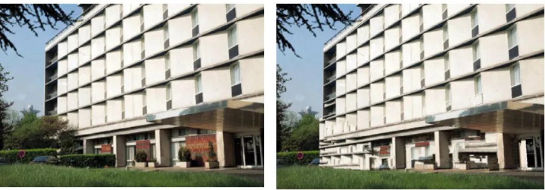
Perspective inpainting We fill the area where foreground obstacle objects are removed by perspective inpainting. The façade result after inpainting will maintain the structural feature of the building. Thus the result looks more realistic and convincing to users. However, the inpainting result depends partial on how good the automatic foreground obstacle regions are. The users can manully fix the foreground obstacle regions for more delicate results. We limit the search area of the source patch to be inside the bounding polygon.
(a) (b)
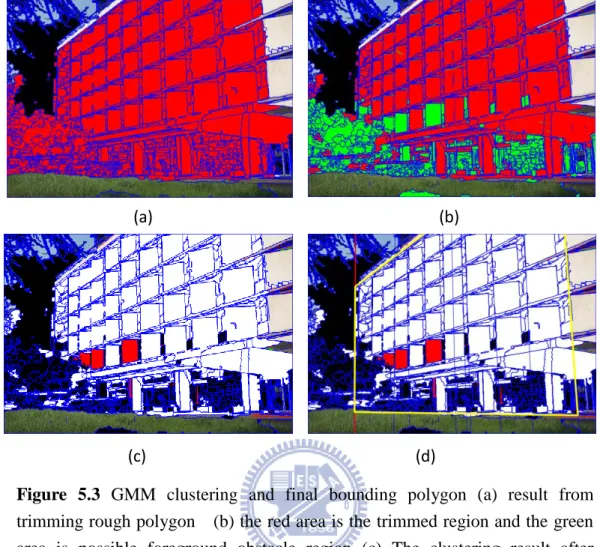
(c) (d)
Figure 5.3 GMM clustering and final bounding polygon (a) result from trimming rough polygon (b) the red area is the trimmed region and the green area is possible foreground obstacle region (c) The clustering result after GMM.The red area prepresents the pixels which in the possible foreground obstacle region are similar to façade,thus add back to façade region (d) the yellow polygon indicates the final bounding polygon of the extracted façade
33
Figure 5.4 Left is the origin input image , right is the perpective inpainting results for foreground obstacle removal.
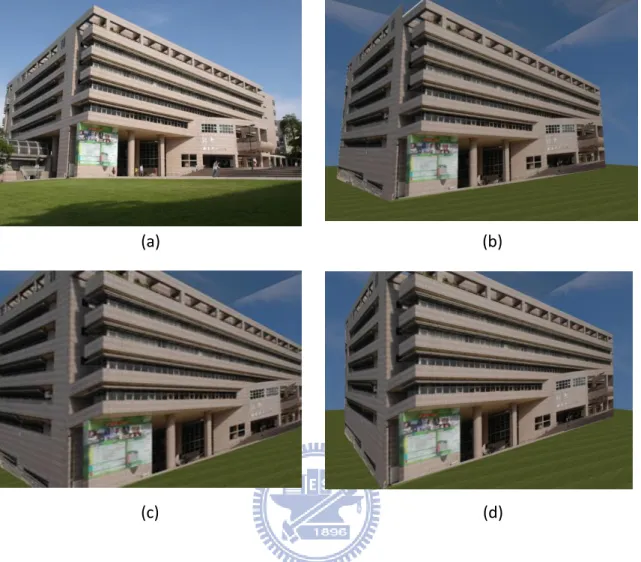
3D scene reconstruction We use OpenGL to reconstruct the scene from the input image using texture-mapped rectangular polygons. The extracted façades are textured to rectangular polygons and the approximate 3D orientation of each façade billboard is computed using pairs of symmetric points from the bounding polygon [LYO02]. The foreground obstacles can be added back into the scene, and reconstruct their spatial relationship with the building like billboards. The scene reconstruction results are shown in Figure 5.5
Figure 5.5 (a) is the origin input image (b) is the reconstruction 3D scene of the input. (c) (d) is the scene from different view point of the reconstructed model
(a) (b)
34
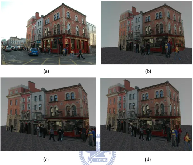
Here we present another result of 3D reconstruction model from the scene. In this case, we manage to extract the main façade (the right-hand side façade )of the building and the sub-façade (the left-hand side façade ) in the image and construct texture-mapped rectangular polygons to build the model. We first input the original image and extract the main façade of the building, then we separate the image into two parts: right part, which contains the main façade, and left part which contains the sub-façade. The left part of the image is subsequently treated as another input to our system and we can extract the sub-façade of the building. In the 3D scene reconstruction process, we reconstruct main façade and sub-façade individually into texture-mapped billboards and combine them together into a single 3D model. The main façade and sub-façade extraction result are shown in Figure 5.6. Figure 5.7 shows the final 3D scene reconstruction result. Figure 5.8 shows another example of 3D scene reconstruction from a single urban street image.
Figure 5.6 Modeling procedure.The top row are the extraction result of the main façade of building. Left image is the original input image, and right image is the extraction result from the original input. Bottom row are the extraction result of sub-façade of the building. We separate image using the extraction result from the original input.
35 Figure 5.7 (a) is the origin input image (b) is the reconstruction 3D scene of
Input image, combining the main façade and the sub-façade of the input image. (c) (d) is the scene from different view point of the reconstructed model
(a) (b)
36
Figure 5.8 (a) is the origin input image (b) is the reconstruction 3D scene of Input image, combining the main façade and the sub-façade of the input image. (c) (d) is the scene from different view point of the reconstructed model
(a) (b)
37
Chapter 6
Conclusion and Future Work
6.1 Conclusion
In this thesis, we present an automatic method to extract the building façade from a single street view image by exploit the relation between architectural features and vanishing point, and further reconstruct a primitive 3D street scene from the input image. Our approach is validated on urban street scene images with rectilinear architecture. The voting-based vanishing point prediction demonstrated satisfactory estimation of the vanishing points from the input images. The process of building façade extraction and refinement achieved stable and reasonablr results and the automatic obstacle objects detection and removal can offer user more friendly interaction with our system.The prespective inpainting technique preformed siginificant improvement by considering the 3D information and the spatial plane of inpainting region
6.2 Future Work
We can improve our system in two aspects : one is to handle more complex scene from input image and the other is to deal with more details in façade extraction. For more complex scene, we attempt to process a multi-façade building and several different buildings at the same time from the input image. If we can extract individual façade from a multi-façade
38
building or from different building, it can help to reconstruct more sophisticate and delicate 3D model from the input scene. Further, we try to apply shape grammars with image analysis to preserve more details of building façade, such windows and doors. Then we can process those detail features, like embossing the windows or undercutting the doors, to make the reconstruction result more realistic and convincing.
39
References
[ADV03] A. Almansa, A. Desolneux and S. Vamech, " Vanishing Point Detection without Any A Priori Information" IEEE Transactions on Pattern Analysis and Machine Intelligence, 25(4):502-507, 2003
[ANT00] M. E. Antone and S. Teller., " Automatic recovery of relative camera reotations for urban scenes. " IEEE Conference on Computer Vision and Pattern Recognition , 2000
[ALC05] D. G. Aguilera, J. G. Lahoz, and J. F. Codes, " A new method for vanishing points detection in 3d reconstruction from a single view. " Proceedings of the ISPRS Commission, 2005
[Barn 83] S. T. Barnard, "Interpreting perspective images, " Artificial Intelligence 21(4):435-462, 1983
[CAN86] J. Canny, " A computational approach to edge detection."
IEEETransactions on Pattern Analysis and Machine Intelligence,8(6):679–698, 1986.
[CAP 90] B. Caprile and V. Torre, " Using vanishing points for camera calibration. "
International Journal of Computer Vision, 4(2):127-139, 1990
[CCTPC10] T.J. Cham, A. Ciptadi, W.C. Tan, Minh-Tri Pham and L.T. Chia ,
" Estimating Camera Pose from a Single Urban Ground-View Omnidirectional Image and a 2D Building Outline Map ", Proceedings of IEEE Conference on Computer Vision and
Pattern Recognition, 2010.
[COM02] D. Comanicu, P. Meer, " Mean shift: A robust approach toward feature space analysis." IEEE Trans. Pattern Anal. Machine Intell., 24, 603-619, May 2002.
[COU 99] J. M. Coughlan and A. L. Yuille , " Manhattan world : Compass direction from a single image by Bayesian inference. " International Conference on Computer Vision, 1999
[COU 03] J. M. Coughlan and A. L. Yuille, " Manhattan world :Orientation and outlier detection by Bayesian inference. "Neural Computation, 15(5):1063-1088, 2003
[CPT04] A. Criminisi, P. Perez and K.Toyama, " Region Filling and Object Removal by Exemplar-Based Image Inpainting " IEEE Transactions on Image Processing ,VOL.13, NO9,
40 SEP 2004.
[DOH72] R. O. Duda. and P. E. Hart., " Use of the Hough Transformation to Detect Lines and Curves in Pictures. " Comm. ACM, Vol. 15, pp. 11–15 ,January, 1972
[DVL06] P. Darko, S. Volker and K. Leif, " Interactive image completion with perspective correction. " The Visual Computer, Vol. 22, pp. 671-681(9),
[GJMR 10] Rafael Grompone , Jérémie Jakubowicz ,Jean-Michel Morel , Gregory Randall , " LSD: a Line Segment Detector ", IEEE Transactions on Pattern Analysis and Machine
Intelligence, 2010
[HAH05] D. Hoiem, A.A. Efros, and M. Hebert, "Automatic Photo Pop-up", ACM
SIGGRAPH 2005
[HAR88] C. Harris and M. Stephens ,. " A combined corner and edge detector ",
Proceedings of the 4th Alvey Vision Conference. pp. 147–151,1988
[KAP09] H. Kong, J.Y. Audibert and J. Ponce , " Vanishing point detection for road detection, " In conference on Computer Vision and Pattern Recognition (CVPR), 2009 [KZ02] J. Košecká and W. Zhang , "Video compass. "European Conference on Computer
Vision , page 476-490, 2002
[LYO02] I-Chen Lin, Jeng-Sheng Yeh, Ming Ouhyoung, "Extracting 3D Facial Animation Parameters from Multiview Video Clips ," IEEE Computer Graphics and Applications (special issue on Tracking), 22(6):72-80, Nov.-Dec. 2002. (SCI, EI)
[MZW07] Pascal Müller, Gang Zeng, Peter Wonka and Luc Van Gool
"Image-based Procedural Modeling of Facades ".Proceedings of ACM SIGGRAPH ACM Transactions on Graphics ,2007
[RKB04] C. Rother, V. Kolmogorov, and A. Blake, "GrabCut: Interactive foreground extraction using iterated graph cuts", ACM Transactions on Graph., vol. 23, pp. 309–314, 2004.
[ROT02] C. Rother , " A new approach to vanishing point detection in arcitectual environments ", Image and Vision Computing , 20(9-10):647-655, 2002
41
[SD04] C. Rother , " A new approach to vanishing point detection in arcitectual environments ", Image and Vision Computing , 20(9-10):647-655, 2002
[SKF06] G. Schindler , P. Krishnamurthy and F. Dellaert, "Abstract Line-Based Structure From Motion for Urban Environments ",In 3DPVT, 2006
[SSS08] S. Sinha, D. Steedly, R. Szeliski, M. Agrawala, "Interactive 3D Architectural Modeling from Unordered Photo Collections", Proceedings of SIGGRAPH Asia, December 2008. 159:1-159:10., 2008
[XFZ09] J. Xiao, T. Fang, P. Zhao, M. Lhuillier and L. Quan, " Image-based Street-side City Modeling", ACM Transactions on Graph , 28(5):#114,1-12, 2009
[ZFX10] P. Zhao, T. Fang, J. Xiao, H. Zhang, Q. Zhao, and L. Quan",Rectilinear Parsing of Architecture in Urban Environment" , IEEE Conference on Computer Vision and Pattern

![Figure 2.2 3D model from a single image by [HAH05]](https://thumb-ap.123doks.com/thumbv2/9libinfo/8367046.177279/17.892.237.706.878.1023/figure-d-model-from-single-image-by-hah.webp)