Energy Harvesting Electronics for Vibratory Devices
in Self-Powered Sensors
Paul C.-P. Chao, Member, IEEE
(Invited Paper)Abstract—Recent advances in energy harvesting have been in-tensified due to urgent needs of portable, wireless electronics with extensive life span. The idea of energy harvesting is applicable to sensors that are placed and operated on some entities for a long time, or embedded into structures or human bodies, in which it is troublesome or detrimental to replace the sensor module bat-teries. Such sensors are commonly called “self-powered sensors.” The energy harvester devices are capable of capturing environ-mental energy and supplanting the battery in a standalone module, or working along with the battery to extend substantially its life. Vibration is considered one of the most high power and efficient among other ambient energy sources, such as solar energy and temperature difference. Piezoelectric and electromagnetic devices are mostly used to convert vibration to ac electric power. For vi-bratory harvesting, a delicately designed power conditioning cir-cuit is required to store as much as possible of the device-output power into a battery. The design for this power conditioning needs to be consistent with the electric characteristics of the device and battery to achieve maximum power transfer and efficiency. This study offers an overview on various power conditioning electronic circuits designed for vibratory harvester devices and their applica-tions to self-powered sensors. Comparative comments are provided in terms of circuit topology differences, conversion efficiencies and applicability to a sensor module.
Index Terms—Electromagnetic, piezoelectric, power condi-tioning, self-powered sensor, vibratory energy harvester.
I. INTRODUCTION
D
EVELOPMENT of standalone, portable wireless sensors, and wearable electronic devices over the past decades have been in a fast pace. Part of this is attributed to recent advances in small-scale electronics and communication tech-nology. However, portable electronics requires the use of elec-trochemical batteries for supplying electrical energy to the sen-sors or devices [1]–[5]. Unfortunately, the development ofbat-Manuscript received September 02, 2011; accepted September 02, 2011. Date of publication September 15, 2011; date of current version October 28, 2011. This work was supported in part by the National Science Council of R.O.C under the Grant NSC 97-2221-E-007-050, and are grateful to the National Center of High-performance Computing for providing excellent computation capacity and National Chip Implementation Center (CIC) of Taiwan for implementing the en-ergy harvest circuit, and in part by the National Science Council, Taiwan, on es-tablishing “International Research-Intensive Centers of Excellence in Taiwan” (I-RiCE Project) under Contract NSC 99-2911-I-010-101. The associate ed-itor coordinating the review of this paper and approving it for publication was Prof. Krikor Ozanyan.
The author is with the Department of Electrical Engineering, National Chiao Tung University, Hsinchu, Taiwan 30010 (e-mail: pchao@mail.nctu.edu.tw).
Color versions of one or more of the figures in this paper are available online at http://ieeexplore.ieee.org.
Digital Object Identifier 10.1109/JSEN.2011.2167965
tery technology has not matched the pace of other electronic components and devices. Based on commonly required power level for the wireless sensors and wearable devices, the battery available either does not have enough power density to survive for a long time or comes in a size too bulky for the electronic de-vices to meet specifications. Furthermore, in medical uses, bat-teries pose a potential toxic threat in implanted in vivo sensors, not to mention that their disposal is environmentally hazardous. Therefore, in an effort to provide the portable devices with re-quired power for their expected lifetime or extended their usage while reducing their size, researchers have turned to possibili-ties of scavenging energy from environment and converting it to electrical energy for devices, equipping the sensors as self-pow-ered modules.
Ambient energy sources available for scavenging are generally from thermoelectric power generation [6]–[9], radio-frequency (RF) power conversion [10]–[12], solar en-ergy conversion [13]–[15], and vibration-to-electrical enen-ergy conversion [16]–[18]. Thermoelectric generation is available mostly from thermocouples. The energy harvesting is based on a small temperature difference or heat flowing between different media. With a fine-designed conversion module, the thermal energy can be successfully converted to dc power. However, related research has been conducted for decades without a significant breakthrough for collecting an adequate amount of useful power until recent days. As another option, the conversion of RF waves into electrical power transforms the unused background radiation in the environment into the power source for driving circuits in a RF module. The scavenged energy is little, but is required to be enough for decoding RF signals. As for solar energy, solar cells are the most mature and commercially established energy-harvesting solution. However, they are not suitable for portable small-scale devices due to their lower-power density generated per unit area and the possible unavailability of lighting. Based on the above, the vibration-to-electrical energy conversion becomes the best choice for self-powered portable sensors due to its ubiquitous availability, high conversion efficiency, and scalability to small sizes [19]. Therefore, the main focus of this study is on the development of vibratory energy harvest devices and the asso-ciated electronics designed for high-power efficiency.
A number of research papers have been dedicated to energy harvest device development and associated electronics for different forms of vibration-to-electrical energy conversion. They can be classified by different mechanisms of transduc-tion: 1) piezoelectric; 2) electromagnetic; and 3) electrostatic
to the topic. The design and development of suitable electronics for the energy harvesters started during the past decade. A basic circuit structure consisting of a diode rectifier and an interface bucket capacitor [20] can be used for power conversion. This circuit is commonly described as a direct charging circuit. This circuit usually results in low-efficiency if the charge-discharge rate predetermined by passive components in the circuit does not match the load resistance. For maximizing power transfer, the impedances of both the power conditioning circuit seen by the harvester and the harvester device itself should be tuned to be matched, to satisfy basic power electronics principles. The impedance match can be achieved either by the use of switching converters with inductors or switched capacitor circuits with pretuned passive components.
This review presents a summary on the power conditioning circuits and some related self-powered sensors which have been developed. The main focus will be on two general different forms of vibratory harvester devices, i.e., piezoelectric and elec-tromagnetic devices. Section II discusses power conditioning circuits developed to date, while Section III offers a review of the self-powered sensors readily or already commercialized. Fi-nally, the conclusion is given in Section IV.
II. POWERCONDITIONINGCIRCUITS
With significant recent advances in energy harvest devices, researchers have seen as a means for improvement the design optimization of the succeeding power conditioning circuitry and storage medium. The following survey studies have inves-tigated various ways to alter the electrical circuit that extracts and stores energy from different devices, such as the aforemen-tioned piezoelectric and electromagnetic devices. The circuits to be discussed are categorized to those with: 1) direct charging; 2) switching converters with inductors; and 3) switched capaci-tors without induccapaci-tors. Note that the aforementioned switching converters are vastly designed for only piezo-harvesters, while the other circuits such as direct charging and switched capac-itors can be used for both piezoelectric and electromagnetic devices.
A. Direct Charging
Shenck and Paradiso in 2001 [20] at the MIT Media Lab-oratory presented a pioneer energy-scavenger unit that consti-tutes an essential part of a RFID tag, as shown in Fig. 1. The study proposed a shoe-mounted piezoelectric generator with a complete subsequent power conditioning circuit, as shown in Fig. 2. The circuit supports an active RF tag that transmits a short-range, 12-bit wireless identification (ID) code while the wearer walks. The adopted power conditioning circuit was ini-tially designed with a basic linear regulation scheme that con-sists of a front-end rectifier, a bucket capacitor, a regulating tran-sistor enabling cold startup and a low dropout (LDO) regulator
Fig. 1. A shoe-mounted piezoelectric generator by Shenck and Paradiso in 2001 [20].
to a battery. Combined front-end blocks of a rectifier, a bucket capacitor and a regulating transistor represent a basic circuit topology of “direct charging” for energy harvest, a schematic of which is depicted in Fig. 3. Due to the piezoelectric generator characteristics of high-voltage, low-energy, low-duty cycle cur-rent pulses at approximately one cycle per second, the vibratory energy could not be stored efficiently by this linear regulator. To solve the problem, they proposed an offline, forward-switching DC–DC converter which outperforms the linear regulator, since the switching converter is more efficient with some difference between input and output voltages. The converter was realized using commercially available discrete components and ICs for testing. This converter resulted in efficiency of 17.6%, more than twice the efficiency of the basic linear regulator.
Ng and Liao in 2004 and 2005 [21], [22] also developed a piezoelectric energy harvest system which includes a power cir-cuit to collect the low-level energy extracted from the piezoelec-tric device for communication systems. The circuit consists of a piezoelectric device, a rectifier diode, a bucket capacitor, and a voltage monitoring circuit block to the drive a load. The energy generated by the piezoelectric material is first rectified with a diode and then stored in an interface capacitor. A voltage mon-itoring circuit is connected to the bucket capacitor and releases energy from the capacitor in burst mode. The monitoring circuit senses the voltage across the bucket capacitor to identify the timings for the capacitor to discharge to the load; otherwise, the bucket capacitor collects the energy extracted from the piezo-electric device. With properly chosen component specifications, the monitoring circuit is able to discharge the bucket capacitor at high voltage level (release voltage), while stop discharging at slightly lower capacitor voltage level (detect voltage). The effi-ciency of the power harvesting circuit is shown to be capable of reaching 46%.
There have been other related research papers also using direct charging published later, such as Tayahi et al. in 2005 [23]. In that work, a circuit is developed containing a rectifier, a bucket capacitor, a discharge management subcircuit and a Linear Technologies LTC1474 voltage regulator that supplies voltage to the load. The discharge subcircuit senses the battery voltage and compares this with the bucket capacitor voltage to determine the timing of the charge and discharge. However, the
Fig. 2. The power conditioning circuit by Shenck and Paradiso in 2001 [20].
Fig. 3. Standard energy harvesting interface: Direct charging.
Fig. 4. The power conditioning circuit topology adopted by Ottman et al. [24], [25].
testing results are not clearly shown to validate the expected performance.
B. Using Switching Converters With Inductors
To deal with the power transfer efficiency of direct charging for power conditioning circuit, Ottman et al. in 2002 [24] proposed a switching scheme with an adaptive duty approach to maximize the power transfer in an online fashion. The adopted circuit topology is shown in Fig. 4. The study treated the front-end piezoelectric device as a parallel combination of a harmonic current source and a capacitor. It was proven that the peak power occurs when the rectifier output voltage reaches
(1) where is the rectifier output voltage, and are the equivalent current source and capacitance of the piezoelectric device, respectively, and is the device oscillating frequency. Note that the peak current varies with different duty cycles. In addition to a rectifier and a bucket capacitor designed, a step-down (buck) converter is employed prior to the battery. The
switching duty cycle of the converter is tuned adaptively for maximizing the battery current sensed by a small resistor in con-junction with the battery. From (1), it follows that the optimal duty cycle changes dramatically with the excitation frequency. Experimental studies were conducted and yielded an optimal duty cycle of 3.18% for the maximum current. With this duty cycle, it is shown that the proposed dc-dc converter increases the power transfer by over 400%. Ottman et al. in 2003 [25] further established the power model for the circuit, where the duty cycle is analytically optimized to satisfy (1), yielding
(2) where is the optimal duty cycle; is the inductance and is the switching frequency. The above equation shows that the optimal duty cycle is essentially a constant, once the design specifications of the piezoelectric device are determined, greatly simplifying the control implementation of the step-down con-verter. Experimental studies showed that the controller is stabi-lized at a duty cycle of 2.8%, which is slightly smaller than that for maximum output current from the piezoelectric device [24]. This self-powered converter can increase the harvested power up to 325% of that in which the battery was charged directly by a rectifier circuit. In a related study by Kim et al. in 2004 [26], an experimental study was conducted on a cymbal piezoelec-tric transducer for finding the optimal duty cycle of the adopted switched-mode converter. Targeted mechanical vibrations were in the range of 50–150 Hz with force amplitude in the order of 1 kN (automobile engine vibration level). The experiments were performed at the frequency of 100 Hz on a 29 mm di-ameter and 1 mm thick cymbal under a force of 7.8 N. Under these conditions, the cymbal generated 39 mW power across a 400 resistor. A dc-dc converter was designed which allowed the transfer of 30 mW power to a low impedance load of 5 with an optimal 2% duty cycle and at a switching frequency of 1 kHz. However, the study did not present theoretical analysis and design.
Considering the damping effects induced onto the piezoelec-tric generator device by the power conditioning circuit shown in Fig. 4, Lesieutre et al. in 2004 [27] derived the equivalent damping loss factor as the dc-dc converter is driven to maximize power transfer. The associated loss factor was successfully derived, which is evidently dependent on the electromechanical
Fig. 5. Synchronous electric charge extraction (SECE) by Lefeuvre et al. in 2005 [29].
coupling coefficient. Experiments on a base-driven piezoelec-tric cantilever, having a system coupling coefficient of 26%, yielded an effective loss factor for the fundamental vibration mode of 2.2%, in excellent agreement with theory. A later study by Ammar et al. in 2005 [28] developed another on-line duty-adjusting algorithm for the dc-dc step down converter. The adaption law is relatively straight forward. It starts with an initial low duty cycle value and measures the current flowing into the battery. The controller then increments the duty cycle value and each time the duty cycle is incremented, the current flowing into the battery is measured and compared to the previously obtained current measurement. If the change in duty cycle results in an increased current, the duty cycle is again increased. The circuit was realized and tested without power being analyzed.
Lefeuvre et al. in 2005 [29] proposed another self-adaptive power conditioning and management circuit, as shown in Fig. 5. The circuit consists of a diode for rectification and a flyback dc-dc converter. The energy generated by the piezoelectric device is extracted in a fashion that the switching of the flyback converter is controlled to be in synchronization with electric charge extraction, so called “synchronous electric charge
ex-traction (SECE).” When the voltage across the diode reaches
maximum, the converter is activated for transferring the charge to the battery. On the other hand, when charge in the piezo-electric device is depleted, the conversion is deactivated until the voltage is sensed to be at its maximum again. The overall conversion efficiency is proven to be over 400% as compared with the standard direct charge method. From a mechanical point of view, the SECE technique may be seen to be equivalent to the Synchronized Switch Damping on Short-Circuit (SSDS) damping technique proposed by Lallart et al. in 2008 [30]. Another similar circuit was proposed by Wu et al. in 2009 [31] with new switching strategy, which is named Synchronized Switching and Discharging to a storage Capacitor through an Inducto (SSDCI), the topology of which is shown in Fig. 6. This is essentially a circuit performing direct charging in the first part, succeeded by a basic buck converter. The added inductor is particularly responsible for storing the energy as the piezoelectric device is discharging. The potential energy loss during discharge is expected to be recovered by the inductor.
Guan and Liao in 2007 [32] presented a comparison work be-tween the cases with and without active power conditioning cir-cuits for harvesting energy generated by a vibrating piezoelec-tric device. The active power conditioning circuit refers to the
Fig. 6. Synchronized switching and discharging to a storage capacitor through an inductor (SSDCI) by Wu et al. in 2009 [31].
Fig. 7. The buck-boost dc-dc converter by Cantatore and Ouwerkerk in 2006 [33].
one containing the block with an active switch, an inductor and possible by a diode. Since the active circuit has one more stage than the conventional one, it is named a “two-stage” energy har-vesting circuit, as opposed to the conventional “one-stage” cir-cuit. This two-stage circuit topology is in fact follows the struc-ture proposed by Ottman et al. in 2003 [25], but arrives at a more complicated optimal duty cycle. It is found that the one-stage energy harvesting scheme has a higher harvested efficiency by choosing an optimal energy storage device voltage as compared with the two-stage scheme within the given input range. How-ever, since the input electric power from the piezoelectric de-vices are not necessarily in a regular harmonic form, one-stage structure would often fail to achieve high efficiency when the piezoelectric device vibrates irregularly.
There were other studies essentially adopting a conventional buck-boost converter after the rectification. The switching duty of converter was tuned in a passive or active manner. For ex-ample, a buck-boost dc-dc converter was adopted by Cantatore and Ouwerkerk in 2006 [33] after the rectifier, the switching duty of which is tuned to match the impedance of the energy harvester for maximum power transfer. The circuit topology is shown in Fig. 7. The study pointed out that it is easier if the electric-induced damping in the harvester device is weakly de-pendent on the load current. This might be the case for a piezo-electric device, but it is difficult to achieve for electromagnetic generators. For a vibratory electromagnetic power generator,
Cao et al. in 2007 [34] presented a high- efficiency energy har-vest circuit implemented by the 0.35 CMOS process. The circuit mainly consists of a rectifier and a feedforward/feedback dc-dc PWM boost converter. The circuit is able to adjust the duty based on varied input voltage and the voltage of the storage ele-ment, a super capacitor, to achieve high energy conversion effi-ciency. Using a mini-shaker as vibration source, the maximum output power reaches 35 mW, adequate to drive their commer-cial accelerometer. Xu et al. in 2007 [35] proposed a pulsed-res-onance ac-dc converter for energy harvesting. The converter was a combination of bridge rectifier, buck-boost converter and a control IC implementing pulse drives to the switches in the con-verter. Energy harvesting for battery charging had been demon-strated using a power source offering up to a few microwatts. Conversion efficiency of 70% has been achieved experimentally. Recently, Vijayaraghavan and Rajamani in 2010 [36] pro-posed three different algorithms to determine the timings for switchings with particular consideration of short duration vibra-tions. They were so-called “fixed threshold switching,” “max-imum voltage switching,” and “switched inductor.” These al-gorithms determined the switching timings based on the bucket capacitor voltage after rectification, this is, in fact, equivalent to the concept of power management. Theoretical and exper-imental results showed that the algorithm of “fixed threshold switching” outperformed the others in terms of the lowest power consumption. D’hulst et al. in 2010 [37] presented a power pro-cessing circuit for vibration energy harvesting with considera-tion of two different loads: a resistive load and an ac-dc recti-fier load. Two modes of power processing are designed for em-ulating desired input impedance and a constant input voltage. The optimal processing is achieved by a combination of pre-vious two modes, reaching an efficiency of 64%. Most recently, Dayal et al. in 2011 [38] proposed a single-stage ac-dc con-verter for power processing of an electromagnetic generator ca-pable of outputting a few hundred millivolts. Of particular de-sign is the utilization of inherent electromagnetic coils in the generator as an inductor in a series connection with the gener-ator in the equivalent circuit considered for analysis and design. Such design leads to higher efficiency and a compact package. Switching timings were determined with the aim to shape the input current form from generator for maximum power output. An efficiency of 56% was achieved.
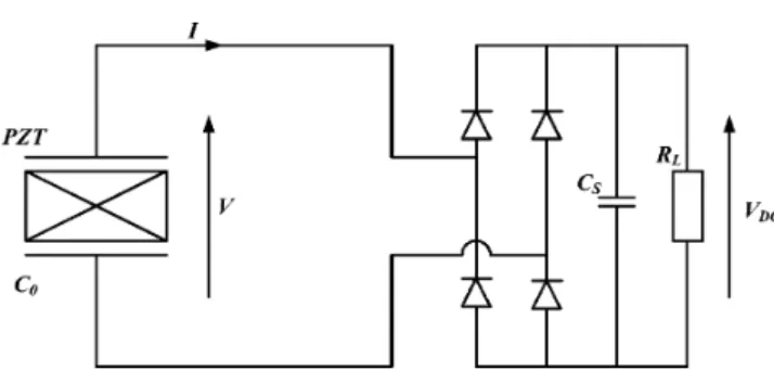
All of the aforementioned power conditioning circuit topolo-gies adopt a conventional buck or boost converter after the diode rectifier. These circuit topologies are basically applicable to ei-ther piezoelectric or electromagnetic harvesters. Dissimilar to these designs, some researchers interested in piezoelectric vice proposed to add an inductor between the piezoelectric de-vice and the rectifier. This largely aims to form an early energy exchange via electrical oscillation between the capacitive-type piezoelectric device and the inductor. Lefeuvre et al. in 2004 [39], Badel et al. in 2005 [40] and Guyomar et al. in 2005 [41] proposed another scheme and circuit for extracting the elec-tric charge from elecelec-tric devices, which is named synchronous switch harvesting on inductor (SSHI), where the inductor is placed between the harvester device and the rectifier. The cir-cuit topology is shown in Fig. 8. The entire power conditioning circuit consists of rectifier diodes, bucket capacitor, load (or
bat-Fig. 8. Synchronized switch harvesting on inductor (SSHI): Parallel SSHI.
Fig. 9. New circuit for SSHI by Makihara et al. in 2006 [42].
Fig. 10. Series-SSHI.
tery), and a combination of a switch and an inductor in a se-ries connection with the piezoelectric device and other circuit components; hence, the name of the designed circuit topology is “parallel-SSHI.” The switch in series with the inductor is placed between the piezoelectric device and succeeding rectifier, ca-pacitor and load battery. The switch closes on a displacement maximum, allowing charge to be transferred to the battery. Once the voltage on the piezoelectric element has been reversed, sig-naling that all of the charge has been removed, the switch is opened and energy transfer is stopped. Makihara et al. in 2006 [42] proposed a combination of two diodes and an active switch to replace the original four-diode-rectifier, as shown in Fig. 9. This aims to improve the lost efficiency caused by inevitable voltage drops across diodes. Experimental results show that the proposed circuit successfully increases the harvested power as much as 120% compared to a typical SSHI.
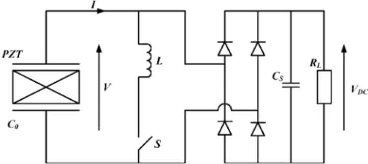
Other research works such as Lefeuvre et al. in 2005 [43] and 2006 [44] started to consider the possibility of the topology for energy harvesting in “series-SSHI,” as shown in Fig. 10. The switching device in the designed circuit is placed in a series conjunction with the piezoelectric device. The switch control strategy is the same as in the case of the parallel-SSHI circuit.
Fig. 11. DSSH by Lallart et al. in 2008 [45].
Theoretical analysis and experimental studies were conducted for both SSHI techniques, the performance of which are com-pared to the conventional direct charge circuit and to each other. It was found that the power gain of the proposed techniques is above 15 compared with the conventional direct charge configu-ration. It should be noted at this point that both SSHI techniques harvested about the same maximum power, but the matching re-sistive load of the series-SSHI technique was about four orders of magnitude lower than that of the parallel-SSHI technique. It was concluded that, under a constant force excitation environ-ment, the synchronous electric charge extraction method will be the most efficient, and under a constant displacement exci-tation environment, the parallel and series-SSHI methods have the highest efficiency when resistive loads are matched.
To equip the SSHI technique with the capability of tuning the damping (impedance) of the power conditioning circuit seen by the piezoelectric device, a circuit of Double Synchronized Switch Harvesting (DSSH) was proposed by Lallart et al. in 2008 [45], as depicted in Fig. 11. This approach consists first of transferring a part of the electrostatic energy from the piezoelectric element to an intermediate storage capacitor , using the remaining energy for the inversion process, and then transferring the energy on to the inductance and finally to the storage stage. Through the passive tuning of the capac-itances, the damping (impedance) of the power conditioning circuit has the chance to match that of the harvester device, yielding maximum power transfer. It can be shown that the har-vested power, considering a constant displacement magnitude, can be six times higher than when using the classical energy harvesting interface. Based on DSSH, Shen et al. in 2010 [46] further proposed a technique of Enhanced Synchronized Switch Harvesting (ESSH) that adopts the DSSH circuit topology; however, in contrast with Lallart et al. in 2008 [45], the switch in the buck-boost converter is operated also according to the voltage level of the interface capacitor between the rectifier and converter. Thus, the ESSH technique dramatically increases the harvested power by almost 300% as compared to the basic direct charge circuit at resonance frequencies in the same vi-bration conditions. It also ensures an optimal harvested power whatever the load connected to the microgenerator.
For further improvement on the conversion efficiency of general SSHI circuits, Garbuio et al. in 2009 [47] proposed a series-SSHI circuit but with a transformer replacing the switched conductance, as shown in Fig. 12. By adjusting the duty of switching, the load seen by the front-end piezoelectric
Fig. 12. SSHI-MR by Garbuio et al. in 2009 [47].
Fig. 13. Hybrid SSHI by Lallart et al. in 2010 [48].
device can be tuned actively; thus possible to achieve maximum power transfer. Witt a transformer, the designed circuit is called Synchronized Switch Harvesting on Inductor using Magnetic Rectifier (SSHI-MR). The designed SSHI with the transformer owns the particular capability of large voltage conditioning. Lallart et al. in 2010 [48] later proposed an alternative structure of SSHI-MR, having the transformer to be combined with a parallel-SSHI and then called a “hybrid SSHI.” The circuit topology is shown in Fig. 13. With this circuit topology, the conduction and harvest can be performed within the same pe-riod of a piezoelectric device oscillation cycle, harvesting more energy as compared to the aforementioned series-SSHI-MR.
Utilizing the concept of a parallel-SSHI circuit, Lallart et al. in 2010 [49] paid effort to extract maximum acoustic energy from a piezoelectric device. A thorough theoretical analysis of the direct charge and parallel-SSHI circuits was conducted. Harvested power was predicted accurately based on the com-parison between the theoretical results and experimental data. The switched power conditioning circuit is seen as impedance change to the piezoelectric device. The effects of damping change on the resonance frequency drift are the main focus in this study. It has been demonstrated that the switching tech-nique allows a great enlargement of the bandwidth in terms of harvested power, as well as a significant increase in the output power for low coupled systems or structures excited out of their resonance.
Liu et al. in 2009 [50] and Lefeuvre et al. in 2009 [51] pre-sented an alternative of series-SSHI with diodes in the rectifier implemented by active switches. The circuit topology is shown in Fig. 14. These switches are controlled by preprogrammed PWM signals, which are responsible for precise inversions and energy harvesting. Due to the controllability of active switches, a better harvested energy level was achieved. However, signifi-cant external power is needed to drive the active switches, con-suming large portion of the energy harvested from the piezo-electric device. Lallart et al. in 2010 [52] further proposed a
Fig. 14. The series-SSHI with active switches by Liu et al. in 2009 [50].
Fig. 15. The series-SSHI with a pulsed energy feedback to the piezoelectric element by Lallart et al. in 2010 [53].
two-step inversion scheme and associated topology. The har-vested energy is successfully increased by a theoretical factor up to 2 (i.e., 40% gain), as compared with classical SSHI. This al-lows an increase of the harvested power by a factor greater than 1000% compared with the standard direct charging technique for realistic values of the inversion components. Most recently, Lallart et al. in 2010 [53] considered a pulsed bidirectional en-ergy flow between the source and the storage stages. The cir-cuit topology is shown in Fig. 15. This standalone energy har-vesting application permits an “energy resonance” effect thanks to a pulsed energy feedback to the piezoelectric element. As all switches in the forward and feedback paths are controlled fol-lowing the predesigned scheme, the proposed circuit allows har-vesting of up to 20 times more energy than in the standard case using off-the-shelf components.
The switching converters discussed in this subsection are generally designed toward maximum power transfer (via impedance) and maximum power efficiency [54], [55]. It is known that the objective of maximum power transfer is usually hampered by the inherent nonresistivity in the impedance of the front-end harvester device and nonlinear rear-end load (such as a battery) [56]–[59]. As for the other objective of max-imum efficiency, it is seriously undermined by the switching loss from power switches, the conduction loss from diodes, switch’s channel resistance, and nonlinearity of other passive components [60], [61], not to mention the power consump-tion from the microprocessor. Extensive theoretical studies [54]–[61] were conducted for finding optimum designs of the switching technique and varied passive components for a given circuit topology. The future design trend is to forge
Fig. 16. The full-wave synchronous rectifiers by Le et al. in 2003 [62].
a switching technique that achieves both maximum power transfer and efficiency, while the complexity of the designed switching algorithm can keep the power consumption of the microprocessor within a tolerable range.
C. Switched Capacitors Without Inductors
Through the power analysis on the aforementioned circuit topologies of direct charging and switched-mode converters, one can often find that one of the significant power losses is caused by the inevitable voltage drops across diodes in the rec-tifier. This power loss becomes detrimental as the input voltage or power is limited to low levels. To minimize the voltage drop, Le et al. in 2003 [62] proposed the so-called “full-wave synchronous rectifier,” which used CMOS transistors as diodes, instead of diodes, in the rectifier. The circuit topology is shown in Fig. 16. The voltage is boosted into a sufficient level for subsequent power conditioning by the circuit structure of a charge pump. The conduction voltage drop on each transistor switch was reduced significantly by employing op-amplifiers across DS terminals of each transistor. The conduction losses on the transistors were reduced to zero with infinite gain posed by the op-amplifiers. The same research group (Han et al. in 2004 [63]) later presented related results on theoretical analysis, design and experiments, achieving over 400% more power than the switched-mode converter. By means of Arbitrary Waveform Generator Representation (AWGR) for the flexing piezoelectric membrane, a maximum output power of 18.8 can be extracted from a single piezoelectric micropower generator (MPG), with 92% efficiency in the rectifier stage. The AWGR of the flexing piezoelectric membrane is also presented. Re-cently, Le et al. in 2006 [64] also presented an extensive work where enabling the clock control of the voltage doubler charge pump via the signal feedback from the CMOS switches which plays the role of diodes in the rectifier. Circuit designs and measurement results are presented for a half-wave synchronous rectifier with voltage doubler, and a passive full-wave rectifier circuit connected to the piezoelectric MPG. It was shown that although the active full-wave synchronous rectifier requires quiescent current for operation, it has a higher peak efficiency of 86% with an 82 load, and higher peak power of 22 W with a 68 load which is 37% higher than the passive full-wave
Fig. 17. On-chip circuit implementation by Mur–Miranda in 2003 [67].
rectifier. Dallago et al. in 2007 [65] presented a voltage doubler and rectifier similar to that in Han et al. [63]. The only differ-ence is the added actively-controlled voltage sources between the op and the drain terminals of the switching CMOS tran-sistors, which allow active control of the voltage drop across the transistor switches. In this way, the power loss due to the conduction power loss of the switches can be regulated. The study presents analysis and simulations for demonstrating the merits of adding voltage sources as compared to other simpler designs. The efficiency of this design is proven to be as high as 88% with a given resistive load of 500 . The designed circuit was implemented later by Dallago et al. in 2008 [66] by a certain chip layout, showing the related experimental results achieving efficiency better than 90%.
Mur–Miranda in 2003 [67] developed on-chip power elec-tronics for electrostatic microgenerators. The proposed circuit is depicted in Fig. 17. This circuit charges and discharges the variable capacitor of the transducer from a reservoir via an inductor using two active MOSFET switches. Theoretical modeling of the designed circuit considering parasitic effects was performed using the SPICE simulator. The circuit was in-tegrated with ICs and MEMS processes. The simulation results show that for around 24 nJ/cycle generated by the moving plate capacitor, only 0.5 nJ is transferred to the output (an electrical efficiency of around 2%). Although energy conversion was demonstrated, difficulties in gate clocking and inefficiencies of the power electronics prevented net energy conversion to a load. Miyazaki et al. in 2003 [68] improved the timing scheme of this topology and achieved 120 nW of converted power from a 45 Hz vibration.
Torah et al. in 2008 [69] developed an electromagnetic gen-erator with a power conditioning circuit to power an RF-linked accelerometer-based sensor system. The circuit was energy aware and adjusted the measurement/transmit duty cycle ac-cording to the available energy. A special voltage multiplier circuit, as shown in Fig. 18 was designed to increase the electrical damping compared to a purely resistive load. This is essentially a Dickson’s charge pump. This circuit allows for an average power of 120 to be generated at 1.7 . The use of charge pumps to increase the transducer output voltage was also presented by James et al. in 2006 [70] and Ching and Li et al. in 2001 [71] and 2002 [72] for electromagnetic generators. James et al. note that this technique is superior to using a transformer not only in terms of electrical efficiency but also because of constraints on size and weight.
Fig. 18. The voltage multiplier circuit by Torah et al. in 2008 [69].
Yen and Lang in 2006 [73] conducted the design and demon-stration of a variable-capacitance vibration energy harvester that combines an asynchronous diode-based charge pump with an inductive energy flyback circuit to deliver 1.8 W to a resistive load. The circuit topology is shown in Fig. 19. This study con-siders a piezoelectric cantilever beam as a variable capacitor with 650-pF dc capacitance and a 348-pF zero-to-peak ac ca-pacitance. The beam is formed by a 43.56 spring steel top plate attached to an aluminum base, driving the charge pump at its out-of-plane resonant frequency of 1.56 kHz. An optimized asynchronous capacitive energy harvester requires only one ac-tive switch, thereby clocking is greatly simplified. The circuit employs a charge pump in its forward harvesting path and an in-ductive energy flyback to return net energy to a central reservoir. It delivers 1.8-W of power to a resistive load, translating to an ef-ficiency of 19.1%. Experimental data prove that net energy con-version does not result from clock energy injection. Kim et al. in 2009 [74] proposed a small-sized self-powered wireless ubiqui-tous sensor node powered with switched capacitor-type power management circuit, which is shown in Fig. 20. The circuit was designed and implemented to fulfill the function of RFID. The circuit is functioned to be activated by wakeup pulse and deac-tivated after RFID signal transmission. Initially Q1 and Q2 are off, and the ground (at the drain of Q2) is floating, hence the subsequent electronics (U1-U3) are unpowered. As the charge scavenged from the harvesters is continuously accumulated in Cs, a wakeup pulse (at least 1.8 V, 100 ms) is finally applied to C4. The transistor Q2 is turned on to transfer the power to the succeeding ICs and loads. The signal transmission is tested suc-cessfully at distance of 20 m every 5 min for 8 hours without external power.
Chao et al. in 2010 [75] and Liao et al. in 2009 [76] presented a synthesis of a new energy harvest system that consists of a hula-hoop transformer, a micro-electromagnetic-generator and an interface energy harvest circuit. The hula-hoop transformer is capable of transforming linear reciprocating motions to rotary ones based on the concepts similar to the hula hoop motions. The mechanical transformer is subsequently integrated with a minia-turized electromagnetic rotary generator of 10 10 2 size and its compact energy harvest circuit chip. In Liao et al. in 2009 [76], the energy harvest circuit adopted a preliminary Dickson’s charge pump topology that requires extra power to generate switch control signals, while Chao et al. in 2010 [75] employed a new dual phase charge pump, power management circuit, a low dropout regulator and battery charger designed and fabricated via the 0.35 process. This charge pump circuit, as shown in Fig. 21, has the merit of automatic conversion of the
Fig. 19. Capacitive energy harvester circuit by Yen and Lang in 2006 [73].
Fig. 20. Power management circuit for the self-powered sensor unit by Kimet al. in 2009 [74].
low-power AC generated by the microgenerator to DC. Exper-iments were conducted to show the favorable performance of the proposed energy harvest system. This is the first work that invents a motion transformer from ubiquitous reciprocating to rotational motion. In this way, more efficient energy conversion via compact-sized rotational electromagnetic generators can be realized as opposed to popular piezoelectric structures.
D. Implementation Issues
In addition to designing a varied power conditioning schemes to maximize conversion efficiency, some realistic implemen-tation issues need to be attended to, such as the development of new energy storage devices, the implementation of control switching and addressing the limitations on the microscale harvester.
Sodano et al. in 2005 [77] conducted a comparison study in storage capabilities between a capacitor and a nickel metal hy-dride battery. A relatively complex charging circuit was used to charge the capacitor, however, a simple full bridge rectifier and
filter capacitor were used to charge the battery. With random and resonant excitation signals applied, it was found the ca-pacitor method performed well, but the high discharge rate of the capacitor did not allow output a smooth, continuous voltage without excessive ripples. Charging the battery requires a rel-atively long time: a few hours, for a capacity of 40 mAh at a voltage level of 1.2 V. However, a battery is commonly known that it can deliver a stable, constant voltage output for a long time. Guan and Liao in 2006 [78] performed a relatively com-plete comparison study of the performance of a super capac-itor: an electric double layer capacitor (EDLC) type, a nickel metal hydride rechargeable battery (conventional type), and a lithium ion rechargeable battery. Charge–discharge efficiencies and lifetimes of these batteries were compared. The super capac-itor manifested the highest efficiency at 95%, while the lithium ion battery was only slightly less efficient than the super capac-itor, yielding a maximum efficiency of 92%. The nickel metal hydride battery was least efficient with a maximum efficiency of 65%. As for the lifetime, super capacitors have virtually unlim-ited charge-discharge cycles, while the other two allow a limunlim-ited number of cycles, in the order of 300–1000. There are though drawbacks of the super capacitor, as opposed to the other two batteries, like a high self-discharge rate. With 30 days elapsed, the storage charge level of the super capacitor could quickly drop to 65% of the full charge level. Nickel metal hydride bat-teries drop to only 70%, while the lithium ion batbat-teries drop only 95%. Finally, supercapacitors have much lower energy densities than the other two rechargeable batteries.
Some implementations of switching control in general SSHI techniques are briefly mentioned below. Published power condi-tioning circuits are naturally employing autonomous switching [79], [80]. For general synchronized switching techniques, the switching time is determined on the detection of device voltage maximum and minimum, which can be realized by computing the derivatives of the voltages or using a delay data memory for the voltages [35], [81]. The later technique is preferred for the lower noise than the alternative. As for limitations on mi-croscale harvester; e.g., MEMS harvesters, the inductors and transformers draw more concerns than the other components since they induce significant electromagnetic interference while conducting. To remedy the problem, Shen et al. in 2007 [82] and Lu et al. in 2008 [83] presented new on-chip inductors and transformers which are suitable for implementations as on-chip
Fig. 21. Dual phase charge pump circuit by Chao et al. in 2010 [75].
devices for microscale energy harvesters. Some other imple-mentation limitations are posed by the inevitable voltage drops across the discrete diodes in the rectifier, which inhibits viable voltage output if the power generated by the front-end device is at low voltage level. This can be improved by including and implementing the diodes in a chip along with the other compo-nents of the power conditioning circuit, or designing an addi-tional step-up circuit for adopting switches with a low conduc-tion voltage drop.
III. APPLICATIONS TOSELF-POWEREDSENSORS
With the availability of energy-harvesting devices and the relatively mature development of power conditioning elec-tronics, researchers endeavored to incorporate the devices and electronics into self-powered sensors, targeting ubiquitous, standalone and movable applications, such as wireless sensor technology, implantable, and wearable biosensors and actu-ators. The sensor unit could contain a battery or not, as the incorporated energy harvesting module is able to scavenge ambient energy to provide continuous electric power to the sensors or prolong battery usage in the sensor unit, even with only intermittent harvested ambient energy available. It is also pertinent to note at this point that most sensors modules employ only basic direct charging circuits or switched capacitors (not the switched converters) due to their simplicity and being able to provide adequate power to activate sensors.
The idea of self-powered sensors and their complete imple-mentation was launched as early as 2001 by Shenck and Par-adiso in 2001 [20] at the MIT Media Laboratory. They presented a pioneer energy-scavenger unit, as shown in Fig. 22, consisting
Fig. 22. Piezoelectric-powered RFID shoes with mounted electronics bv Shenck and Paradiso in 2001 [20].
of a shoe-mounted piezoelectric generator with a complete sub-sequent power conditioning circuit. The unit is designed to con-stitute an essential part of a RFID tag that transmits a short-range, 12-bit wireless identification code while the bearer walks. In addition to the piezoelectric device, electromagnetic devices are also considered due to their high-efficiency and well-estab-lished technology. This RFID serves readily for a personal posi-tioning system for military or police units, a personal navigator or smart pedometer, a data collector for monitoring an athlete’s movements, or a child tracking device.
A foot-mounted rotary generator was proposed by Kymissis et al. in 1998 [84] prior to the work presented by Shenck and Paradiso in 2001 [20]; however, the designed
Fig. 23. A fiber-piezoelectric power harvesting device by Churchill et al. in 2003 [88].
electromagnetic device significantly hampered the wearer’s gait due to the bulky-mechanical components. Nevertheless, it generated as much as 250 mW. Persistent efforts were made by Hayashida in 2000 [85] to develop shoe-mounted electro-magnetic generators at the MIT Media Lab. A smaller-sized electromagnetic harvester was designed with a spring added to sustain continuous, smooth motions of moving magnets for larger, continuous power output, reaching 1 W.
Elvin et al. in 2001 [86] presented the possibility of using a parasitically powered mechanical energy sensor with wireless transmission. The sensor consists of a piezoelectric device con-verting mechanical strain energy into electrical charge and a RF transmitter. The electrical charge is stored and used to power a telemetry system which indicates the average mechanical en-ergy applied to the sensor. A half-diode-bridge is connected to a charging capacitor. A resistor across the charging capacitor is added to the circuit to take into account the voltage leakage. The power scavenged by the piezoelectric device is provided into the telemetry system through a switch. Based on the exper-iment designed, relatively small strains (on the order of 60 ) can be measured and transmitted via a standard AM telemetry system at 1 MHz. In a succeeding work, Elvin et al. in 2003 [87] studied the possibility of combining functions of strain sensing and energy harvesting using a single PVDF piezoelectric de-vice. The device was attached to a beam to sense local strains with the aim to detect structural damage, such as cracks. The energy harvesting function enables transmission of the sensed data to a remote receiver. Along with the functions of strain de-tection and energy harvesting, a wireless communication unit is also incorporated into the module. It was experimentally shown that as the beam is subjected to a vibration of 2.2 mm at a fre-quency of 1 Hz, enough power is generated and transferred to the transmitter via a PDVF patch to perform power conversion. Churchill et al. in 2003 [88] developed a fiber-piezoelectric energy harvesting device to offer power to an adaptive wireless sensor node capable of recording signals from many different transducers and transmitting data successively to a receiver in biomedical applications. The developed harvesting device, as shown in Fig. 23, was in fact a composite device lami-nated with unidirectional aligned piezoelectric fibers (PZT5A, 250 , 13 10 .38 mm in overall). These fibers were embedded in a resin matrix for preventing external damages. Strain energy induced by bending of the device was stored into a bucket capacitor after rectifying the output bipolar voltage of the piezofiber device. The power conditioning electronics
Fig. 24. The integrated transmitter beacon by Roundy et al. in 2003 [89].
is a fundamental type of direct charging along with a power management switch implemented by a low-power comparator LTC1540. It was shown that the piezofiber generator was capable of harvesting up to 0.75 mW of power when subjected to 180 Hz vibrations. The harvested power is responsible for activating a microcontroller (PIC16C series). The micro controller powered up sensor channels, read signals from an on-board AD converter and transmitted data. The transmitter remained powered until the voltage across the bucket capacitor fell below 2.5 V.
Roundy et al. in 2003 [89] presented a transmit beacon that is completely self-powered. The required energy comes from solar energy and vibrations. A customized RF integrated circuit and energy scavenging devices are integrated together to create an efficient beacon at 1.9 GHz, as shown in Fig. 24. Roundy et al. in 2004 [90] further designed a small-sized piezoelectric can-tilever generator that was used for a custom radio transmitter. The total size of the bimorph and mass is approximately 1 . The converter apparently adopted the structure of series-SSHI and was driven with vibrations at 100 Hz and acceleration mag-nitude of 2.25 , roughly equivalent to those measured in a small microwave oven. The radio transmitter consumed 10 mA of current at 1.2 V and was capable of transmitting a 1.9 GHz signal at a distance of 10 m. The output voltage for the vibration sources under consideration is in the range of 3–10 V, while the transmitted power ranges from 20 to 80 mW, which makes it a viable power source for wireless sensor node. Ammar et al. in 2005 [28] later developed a relatively complete RF transmitter powered by an energy harvester, the schematic of which is il-lustrated by Fig. 25. The module includes a microscale-piezo-electric energy harvesting device, an energy harvesting circuit, a microprocessor, a MEMS sensor, onboard memory, an onboard clock, and a RF transmitter. At the same time, Zhou et al. in 2005 [91] also designed a piezoelectric cantilever and comb de-vice for both accelerator sensing as well as an embedded energy harvester to power the accelerometer, which is in the form of an identical piezoelectric cantilever and comb structure. Similar to this research, a number of other studies have successfully in-corporated the piezoelectric energy harvester into the sensors, either within the same or in different wafer processes. Arms et
al. in 2005 [92] presented the design and manufacture of a
wire-less temperature and humidity sensor powered by a piezoelectric energy harvest unit, as shown in Fig. 26, where a piezoelectric
Fig. 25. Schematic architecture of the wireless sensor node by Ammar et al. in 2005 [28].
Fig. 26. A wireless temperature and humidity wireless sensor by Arms et al. in 2005 [92].
cantilever beam was used to harvest ambient vibrations and al-lowed RF transmission. With the piezo-beam under low-level vibration in the order of 1 , it is able to deliver approx-imately 2000 , sufficient for the RF transmitter consuming 300 at 3 VDC (900 ); at 5 Hz: 400 , at 1 Hz: 90 mW. They presented a fully integrated vibration energy harvesting wireless sensor node, which was readily commercialized at the time.
Torah et al. in 2008 [69] reported an energy aware au-tonomous wireless condition monitoring sensor system (ACMS) powered by ambient vibrations. The system is shown in Fig. 27. An electromagnetic generator has been designed to harvest sufficient energy to power an RF-linked accelerometer based sensor system. The ACMS is energy aware and adjusts the measurement/transmit duty cycle according to the available energy. The ACMS has been successfully demonstrated on an industrial air compressor and an office air conditioning unit, continuously monitoring vibration levels and thereby simulating a typical condition monitoring application. Pinna et al. in 2010 [93] presented a complete self-powered vibration-based energy harvest system. The system consists of a piezoelectric energy harvester, an integrated semi-active bridge rectifier and a voltage regulator circuit. The semi-active
Fig. 27. A energy aware autonomous wireless condition monitoring sensor unit by Torah et al. in 2008 [69].
Fig. 28. The generator, with MEMS harvester, its packaging, placement of the chip and SMD components, and chip micrograph by Aktakka et al. in 2011 [95].
bridge rectifier proposed in this study uses a special fabrication process called Vertical Double-diffused MOS (VDMOS) for standard diodes in the rectifier, in order to withstand high terminal voltage differences. An efficiency of 90% has been shown based on SPICE simulation, but not validated experi-mentally. Besides, the power consumption and bias stability for the op-amps employed in the semi-active rectifier and the voltage regulator should be addressed. Most recently, Challa et
al. in 2011 [94] presented a vibration energy harvesting device
with autonomous resonance frequency tenability utilizing a magnetic stiffness technique. A piezoelectric cantilever beam array is employed with magnets attached to the free ends of cantilever beams to enable magnetic force resonance frequency tuning. The device is successfully tuned from to of its untuned resonance frequency, while outputting a peak power of approximately 1 mW. However, for the aim of future commercialization, various system components have to be integrated into a single package. Furthermore, Aktakka et al. in 2011 [95] presented a self-powered energy generator, which includes a MEMS harvester hybrid-integrated with its power management circuitry for autonomous charging of an energy reservoir, as shown in Fig. 28. The proposed packaging of the generator is of . Initial testing results are obtained with an unpackaged MEMS harvester.
For the health monitoring of self-powered machinery, du Plessis et al. in 2005 [96] investigated the feasibility of using a packaged piezoelectric bimorphs for power harvesting in
Fig. 29. A packaged self-powered energy generator by du Plessis et al. in 2005 [96].
Fig. 30. A self-powered sensor node by Discenzo et al. in 2006 [97].
industrial machines. The developed harvester is shown in Fig. 29. It is recommended for a sensor node to consist of six submodules including an energy harvester, power conversion circuitry, a power storage module, a sensor, a processor, and a radio communications unit. Satisfactory experimental corre-lation qualifies the model for future design purposes. Simple power harvesting evaluations for an oil pump with high root strains were performed to determine the maximum power har-vesting capability and the lifetime of a commercially available piezoelectric bimorph in a cantilevered beam arrangement. Results from the test indicate that the bimorph can be strained up to 700 without any material damage, to harvest 2.8 mW at a 100 Hz base excitation. The developed module was readily commercialized. A succeeding work by Discenzo et al. in 2006 [97] was presented to show a self-powered sensor node capable of scavenging energy from an oil pump. The node as shown in Fig. 30 was programmed to sample three analog inputs and data from an accelerometer. This information was stored in the local processor memory and then transmitted to a remote receiver. A special piezoelectric device T220-A4 from Piezo Systems Inc. was used. The resonant frequency of the Cantilever was tuned to match the 130 Hz operational frequency of the oil pump. This study shows a successful application of providing power to the sensors using piezoelectric materials.
The applicability of energy harvest units was extended to biomedical applications. Platt et al. in 2005 [98] presented an implant of a self-powered knee replacement, which embedded a sensor to provide in vivo diagnosis data via RF transmission. The sensor is powered by a piezoelectric energy harvesting de-vice and a related conditioning electronics module. This can be used for the medical uses of a self-powered Total Knee Replace-ment (TKR) implant, as shown in Fig. 31. The power condi-tioning employed a general topology of direct charging with as-sistance from commercial ICs of a low voltage dropout (LDO)
Fig. 31. A self-powered TKR implant by Platt et al. in 2005 [98].
MAX666 and a microprocessor (PIC 16LF872). The harvest unit is able to prolong the lifetime of the implanted diagnostic sensor. A practical prototype was successfully manufactured, capable of providing power up to 0.85 mW for the operation of a PIC 16LF872 microprocessor. The experimental results are limited to relatively high forces ( ) and low frequen-cies ( ). The experimental results were obtained by subjecting piezoelectric elements to various cyclic mechanical loads using a single-axis Mini-Bionix MTS 858 test machine. Approximately 225 of continuous regulated power is avail-able. This is more than adequate to satisfy the approximately 50 power requirement from PIC 16LF872. A succeeding study also by Platt et al. in 2005 [99] presented another knee re-placement unit with a piezoelectric energy harvester providing self-powered capability and sensor function. When subjected to 900 N standard force profile, the harvester is able to output 4.8 mW of continuous raw power, which is well sufficient for providing power to a microprocessor and a sensor node.
Recently, a small-sized self-powered wireless ubiquitous sensor node powered by scavenged energy was reported by Kim et al. in 2009 [74]. Fig. 32 shows the realized sensor unit. This sensor module harvests the energy from a solar cell panel and a vibrating PVDF cantilever beam. A power management circuit, as shown in Fig. 20, was designed and implemented to fulfill the function of RFID. In addition to the two different types of harvesters, there are a microcontroller board, antenna and a power management circuit on a PCB board. The circuit in
Fig. 32. The self-powered sensor unit by Kim et al. in 2009 [74].
the form of switched capacitors is designed to be activated by a wakeup pulse and deactivated after RFID signal transmission. The signal transmission was tested successfully at distance of 20 m every 5 min for 8 h without external power.
IV. CONCLUDINGREMARKS
The progress to date in power conditioning electronics for vibratory energy harvesters, mainly piezoelectric and electro-magnetic devices, were reviewed in this study along with the progress in self-powered sensors reported in the literature. The main focus was on circuit topology differences, conversion ef-ficiencies and suitability for a sensor module. The power condi-tioning circuits were classified to either using the direct charge, switching mode converter or switched capacitors. The switching mode converters were further split into those with an inductor between the harvester device and a rectifier or wihtout. Their operation principles were covered, along with obtained efficien-cies. It appears that the SSHI techniques and their later variants offer better efficiency. However, as far as the compactness of the realistic modules is concerned, the switched–capacitor type converters with a microprocessor show clear advantages. Var-ious self-powered sensor modules were also reported, mostly for wireless sensors and networks. To date, there has been a continuous effort from the part of some pioneer harvester com-panies to persuade consumers that the energy harvester will be a “must” solution, even more so when miniaturization on the sensor module and longer-life spans are both vitally required in the near future.
REFERENCES
[1] T. Starner and J. Paradiso, “Human generated power for mobile electronics,” in Low Power Electronics Design, C. Piguet, Ed. Boca Raton, FL: CRC Press, 2004, ch. 45.
[2] D. Dunn-Rankin, E. M. Leal, and B. D. Walther, “Personal power sys-tems,” Prog. Energy Combust. Sci., vol. 31, no. 5–6, pp. 422–465. [3] P. Baronti, P. Pillai, V. W. C. Chook, S. Chessa, A. Gotta, and Y. F.
Hu, “Wireless sensor networks: A survey on the state of the art and the 802.15. 4 and ZigBee standards,” Comput. Commun., vol. 30, p. 1655, 2007.
[4] [Online]. Available: http://www.xbow.com/
[5] J. L. Hill and D. E. Culler, “Mica: A wireless platform for deeply em-bedded networks,” Micro, IEEE, vol. 22, pp. 12–24, 2002.
[6] H. Böttner, “Micromachined CMOS thermoelectric generators as on-chip power supply,” in Proc. 21st Int. Conf. Thermoelect., Aug. 2002, pp. 511–518.
Caylor, “Energy harvesting for electronics with thermoelectric devices using nanoscale materials,” in Proc. IEEE Int. Electron Devices Meeting, Dec. 2007, pp. 367–370.
[10] L. Anglesio, A. Benedetto, A. Bonino, D. Colla, F. Martire, S. S. Fusette, and G. d’Amore, “Population exposure to electromagnetic fields generated by radio base stations: Evaluation of the urban back-ground by using provisional model and instrumental measurements,” Radiation Protection Dosimetry, vol. 97, p. 355, 2001.
[11] J. B. Burch, M. Clark, M. G. Yost, C. T. E. Fitzpatrick, A. M. Bachand, J. Ramaprasad, and J. S. Reif, “Radio frequency nonionizing radiation in a community exposed to radio and television broadcasting,” Environ. Health Perspect., vol. 114, p. 248, 2006.
[12] P. A. Valberg, T. E. van Deventer, and M. H. Repacholi, “Environ. “Workgroup report: Base station and wireless network ¡Xradiofre-quency (RF) exposures and health consequences”,” Health Perspect., vol. 115, p. 416, 2007.
[13] J. B. Lee, Z. Chen, M. G. Allen, A. Rohatgi, and R. Arya, “A high voltage solar cell array as an electrostatic MEMS power supply,” in Proc. IEEE Workshop MicroElectro Mech. Syst., 1994, pp. 331–336. [14] D. M. Bennett, R. H. Selfridge, and B. P. Humble, “Hybrid power
systems for autonomous MEMS,” in Proc. SPIE Smart Struct. Mater., 2001, vol. 4334, pp. 354–362.
[15] K. Sangani, “Power Solar-The sun in your pocket,” Eng. Technol., vol. 2, pp. 36–38, 2007.
[16] P. Glynne-Jones, M. J. Tudor, S. P. Beeby, and N. M. White, “An elec-tromagnetic, vibration-powered generator for intelligent sensor sys-tems,” Sens. Actuators A, vol. 110, pp. 344–9, 2004.
[17] R. D. Kornbluh, R. Pelrine, Q. Pei, R. Heydt, S. Stanford, S. Oh, and J. Eckerle, “Electroelastomers: Applications of dielectric elastomer transducers for actuation, generation, and smart structures,” in Proc. Smart Structures and Materials Conf., 2002, vol. 4698, p. 254. [18] P. D. Mitcheson, P. Miao, B. H. Stark, E. M. Yeatman, A. S. Holmes,
and T. C. Green, “MEMS electrostatic micropower generator for low frequency operation,” Sens. Actuators A: Phys., vol. 115, pp. 523–529, 2004.
[19] G. Poulin, E. Sarraute, and F. Costa, “Generation of electrical energy for portable devices:: Comparative study of an electromagnetic and a piezoelectric system,” Sens. Actuators A: Phys., vol. 116, pp. 461–471, 2004.
[20] N. S. Shenck and J. A. Paradiso, “Energy scavenging with shoe-mounted piezoelectrics,” Micro, IEEE, vol. 21, pp. 30–42, 2001.
[21] T. H. Ng and W. H. Liao, Feasibility Study of a Self-Powered Piezo-electric Sensor, p. 377, 2004.
[22] T. Ng and W. Liao, “Sensitivity analysis and energy harvesting for a self-powered piezoelectric sensor,” J. Intell. Mater. Syst. Structures, vol. 16, p. 785, 2005.
[23] M. B. Tayahi, B. Johnson, M. Holtzman, and G. Cadet, “Piezoelectric materials for powering remote sensors,” in Proc. IEEE 24th Int. Perform., Comput., Commun. Conf., Phoenix, AZ, Apr. 2005, pp. 383–386.
[24] G. K. Ottman, H. F. Hofmann, A. C. Bhatt, and G. A. Lesieutre, “Adap-tive piezoelectric energy harvesting circuit for wireless remote power supply,” IEEE Trans. Power Electron., vol. 17, no. 5, pp. 669–676, Sep. 2002.
[25] T. S. Ottman, H. F. Hofmann, and G. A. Lesieutre, “Optimized piezo-electric energy harvesting circuit using step-down converter in discon-tinuous conduction mode,” IEEE Trans. Power Electron., vol. 18, no. 2, pp. 696–703, Mar. 2003.
[26] H. W. Kim, A. Batra, S. Priya, K. Uchino, D. Markley, R. E. Newnham, and H. F. Hofmann, “Energy harvesting using a piezoelectric ‘Cymbal’ transducer in dynamic environment,” Jpn. J. Appl. Phys., vol. 43, pp. 6178–6183, 2004.
[27] G. A. Lesieutre, G. K. Ottman, and H. F. Hofmann, “Damping as a result of piezoelectric energy harvesting,” J. Sound Vibration, vol. 269, pp. 991–1001, 2004.
[28] Y. Ammar, A. Buhrig, M. Marzencki, B. Charlot, S. Basrour, K. Matou, and M. Renaudin, Wireless Sensor Network Node With Asynchronous Architecture and Vibration Harvesting Micro Power Generator, pp. 287–292, 2005.
![Fig. 1. A shoe-mounted piezoelectric generator by Shenck and Paradiso in 2001 [20].](https://thumb-ap.123doks.com/thumbv2/9libinfo/7611959.130333/2.891.469.808.99.323/fig-shoe-mounted-piezoelectric-generator-shenck-paradiso.webp)
![Fig. 7. The buck-boost dc-dc converter by Cantatore and Ouwerkerk in 2006 [33].](https://thumb-ap.123doks.com/thumbv2/9libinfo/7611959.130333/4.891.455.826.336.600/fig-buck-boost-dc-dc-converter-cantatore-ouwerkerk.webp)
![Fig. 13. Hybrid SSHI by Lallart et al. in 2010 [48].](https://thumb-ap.123doks.com/thumbv2/9libinfo/7611959.130333/6.891.454.825.274.430/fig-hybrid-sshi-by-lallart-et-al-in.webp)
![Fig. 16. The full-wave synchronous rectifiers by Le et al. in 2003 [62].](https://thumb-ap.123doks.com/thumbv2/9libinfo/7611959.130333/7.891.64.436.344.529/fig-wave-synchronous-rectifiers-le-et-al.webp)
![Fig. 17. On-chip circuit implementation by Mur–Miranda in 2003 [67].](https://thumb-ap.123doks.com/thumbv2/9libinfo/7611959.130333/8.891.454.821.98.237/fig-chip-circuit-implementation-mur-miranda.webp)
![Fig. 19. Capacitive energy harvester circuit by Yen and Lang in 2006 [73].](https://thumb-ap.123doks.com/thumbv2/9libinfo/7611959.130333/9.891.219.674.96.309/fig-capacitive-energy-harvester-circuit-yen-lang.webp)
![Fig. 22. Piezoelectric-powered RFID shoes with mounted electronics bv Shenck and Paradiso in 2001 [20].](https://thumb-ap.123doks.com/thumbv2/9libinfo/7611959.130333/10.891.472.808.566.842/piezoelectric-powered-rfid-shoes-mounted-electronics-shenck-paradiso.webp)
