行政院國家科學委員會專題研究計畫 成果報告
車輛網路系統之嵌入式微處理器實驗教材發展之研究
研究成果報告(精簡版)
計 畫 類 別 : 個別型 計 畫 編 號 : NSC 98-2511-S-018-007- 執 行 期 間 : 98 年 08 月 01 日至 99 年 07 月 31 日 執 行 單 位 : 國立彰化師範大學車輛科技研究所 計 畫 主 持 人 : 楊介仙 計畫參與人員: 碩士班研究生-兼任助理人員:陳冠榮 碩士班研究生-兼任助理人員:許維驛 碩士班研究生-兼任助理人員:蘇揚傑 碩士班研究生-兼任助理人員:吳昇祐 碩士班研究生-兼任助理人員:黃鴻文 報 告 附 件 : 出席國際會議研究心得報告及發表論文 處 理 方 式 : 本計畫可公開查詢中 華 民 國 99 年 10 月 14 日
行政院國家科學委員會補助專題研究計畫
□
ˇ成果報告
□期中進度報告
車輛網路系統之嵌入式微處理器實驗教材發展之研究
計畫類別:□
ˇ個別型計畫 □整合型計畫
計畫編號:NSC 98-2511-S-018-007-
執行期間:98 年 08 月 01 日至 99 年 07 月 31 日
執行機構及系所:國立彰化師範大學 車輛科技研究所
計畫主持人:楊介仙
共同主持人:
計畫參與人員:
黃鴻文、吳昇祐、陳冠榮、蘇揚傑、許維驛
成果報告類型(依經費核定清單規定繳交):□
ˇ精簡報告 □完整報告
本計畫除繳交成果報告外,另須繳交以下出國心得報告:
□赴國外出差或研習心得報告
□赴大陸地區出差或研習心得報告
□
ˇ出席國際學術會議心得報告
□國際合作研究計畫國外研究報告
處理方式:
除列管計畫及下列情形者外,得立即公開查詢
□涉及專利或其他智慧財產權,□一年□二年後可公開查詢
中
華
民
國
九
十
九
年
十
月
八
日
I
-摘
要
本計畫為研究「控制器區域網路(CAN)系統」課程教學法之效果,控制器區域網路乃為車輛網 路系統之一,就近年來車輛電子之發展如雨後春筍般發展,傳統點對點之車輛網路系統已不足以應 付日新月異的車輛電子系統,控制器區域網路系統遂逐漸取代傳統車輛網路系統,因此發展「控制 器區域網路系統」課程將有效訓練學生並增進其車輛網路專業領域之知識及技能,以符相關車輛工 業之人力需求,而該課程對市場之需求益顯重要。而本研究計畫為第一項以「控制器區域網路系統」 相關課程教學法研究之計畫,在此研究過程中,就該工程教育課程而言,吾人建議以引導式之教學 及學習方法較易得到較佳學習效果,諸如詢問式學習法(Inquiry Learning)、問題基礎式學習法 (Problem-Based Learning)、專案基礎式學習法(Project-Based Learning)等,雖是如此,教學上仍應以 課程中不同之內容施以對應不同之學習方法,較易獲得較佳之學習結果。於「控制器區域網路系統」 課程中,吾人發展一車輛電子系統訓練學習板,以此學習板模擬學生可能於未來工作上面臨之實際 問題,學習板上設計一模式切換開關,可切換學習板上之車輛電子系統為傳統點對點連接模式或為 控制器區域網路系統模式,學生於學習過程中可設計控制器區域網路系統以取代傳統線束傳輸模 式,另吾人亦發展一樣品控制器區域網路單元(節點),並於學生設計控制器區域網路單元硬體後, 可由與該樣品單元比較而學習其優缺點。對於不同「控制器區域網路系統」課程單元採用的引導式 混合教學法之教學成效評估,結果顯示修課學生與未修課學生於控制器區域網路系統之通訊協定、 硬體設計、軟體設計及其系統工程均具顯著差異,且修課學生具顯著學習成效,唯取樣數仍顯不足, 更待未來累積更多資料量,做更嚴謹之成效分析。 關鍵詞:控制器區域網路系統、車輛電子系統訓練學習板、詢問式學習法、問題基礎式學習法、專 案基礎式學習法。Abstract
This project reports the results of the study in teaching the course of control area network (CAN) systems, or the vehicle network system. The automotive electronics is essential to vehicle engineering. The vehicle network for electronic units becomes indispensable. The course of control area network (CAN) system designed for vehicles prepares the students for their professional careers in vehicle network and it therefore becomes more crucial. This project studies the pedagogy for CAN system originally. We recommend that the inductive teaching and learning methods such as the inquiry learning, the problem-based learning, and the project-based learning can be adopted in this course. However, it depends on the contents in the course. In this course, we developed an automotive electronic training board that may confront the students with the authentic problems. We also synthesized a pattern CAN unit that assists students in distinguishing their shortcomings or excellences in their hardware design. The evaluation for the hybrid approach of the inductive methods shows that there seemed to be a significant improvement for students in this course although the data were too insufficient to support the hybrid approach.
Keywords: CAN systems, automotive electronic training board, inquiry learning, problem-based learning,
1
-Teaching the Course of CAN System by Using a Simple Training
Board of Automotive Electronics
Abstract
This project reports the results of the study in teaching the course of control area network (CAN) systems, or the vehicle network system. The automotive electronics is essential to vehicle engineering. The vehicle network for electronic units becomes indispensable. The course of control area network (CAN) system designed for vehicles prepares the students for their professional careers in vehicle network and it therefore becomes more crucial. This project studies the pedagogy for CAN system originally. We recommend that the inductive teaching and learning methods such as the inquiry learning, the problem-based learning, and the project-based learning can be adopted in this course. However, it depends on the contents in the course. In this course, we developed an automotive electronic training board that may confront the students with the authentic problems. We also synthesized a pattern CAN unit that assists students in distinguishing their shortcomings or excellences in their hardware design. The evaluation for the hybrid approach of the inductive methods shows that there seemed to be a significant improvement for students in this course although the data were too insufficient to support the hybrid approach.
Keywords: CAN systems, automotive electronic training board, inquiry learning, problem-based learning,
project-based learning.
1. Introduction
Engineering educators continually receive the challenges to make course materials interesting and accessible (learning) and to make knowledge transmissions unequivocal and impressive (teaching) since engineering and its technologies made great progress during these years and the progress will continue faster in the future. The students in Institute of Vehicle Engineering (IVE) of some universities were graduated from universities or vocational colleges. Their disciplines in undergraduate were quite different since they might be major in mechanical engineering, electrical engineering, or vehicle engineering. In addition, they are novices at vehicle network since the courses in undergraduate are fundamental and rarely with applications.
The objective of this paper was to encourage the students in IVE to learn the modern disciplines of vehicle network such as CAN system that differs from traditional one. CAN system is the most widely used network in vehicle systems and the number of CAN nodes has been increased continuously not only in vehicle network systems but in many other applications [1]. The most challenge of all for the instructors is that the students with different disciplines take the same course of CAN systems and the instructors will try to meet the goal of this course that should raise the students to the level on which the students can have enough capability of technique and knowledge of CAN systems. The authenticity of instruction is the trend in higher education and is the relevance of pedagogy to the professional practices of a discipline. The authenticity of instruction is one of the major principles of effective learning and instruction [2-4]. To keep the course of CAN system relevant to industrial needs, the instructors should consider not only the fundamental domain knowledge but also the fidelity and the complexity of the real-life tasks that will confront students in their future careers. Unlike some disciplines of concrete objects in which the use of computer-based technologies can improve the quality of learning, such as manufacturing industries, dynamic systems, chemical industries, fluid mechanics, etc.[5-9], CAN system is
2
-somehow abstract for engineering education. The course of CAN system includes the communication protocol, hardware synthesis, software programming, and system engineering. Instructor should be in good position to investigate some approaches to help learners to develop more expert-like practices and knowledge since expertise is more than the gradual accumulation of knowledge and experience [10-12]. Furthermore, experts can notice features about a given problem that are different from those noticed by novices. Adaptive experts also have knowledge that is well organized and they can display the ability to transfer their knowledge, skills, and attitudes to new situations. Atman et al. has reported on an in-deep study of design processes based on their previous research [13]. Students may be inclined to approach learning such as the surface approach, the deep approach, or the strategic approach [14] . In order to develop students’ professional skills, inductive methods which promote students’ adoption of a deep approach to learning as opposed to a surface approach or a strategic approach [15] seem to be adequate for the course of CAN systems.
In this paper, the course of CAN systems applies some instructional methods from inductive learning methods that impose more responsibility on students for their own learning than the traditional lecture-based approach. Learner-centered environments improve the knowledge, skills, and attitudes of students. This paper highlights the challenges in transmission of knowledge to the students from different disciplines.
2. CAN Systems Course
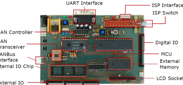
Control Area Network (CAN) has been developed for the vehicle network in mid 1980s by Bosch. It has become the most widely used network in automotive systems and the number of CAN nodes sold each year is currently around 400 million [16]. The purpose of this course is to teach students how to approach the vehicle network design based on CAN system. To provide an intuitive connection between the experiments in laboratory and those in industry, the course developed a low-cost learning board of automotive electronics that has two alternative modes with a network toggle switch as shown in Figure 1. One is the traditional mode in which the control signals of the actuators, such as turn signals, windshield wiping signals, etc, are transmitted by traditional wiring harness. The other is the CAN mode in which those control signals of the actuators are transmitted by CAN system. The students in this course can learn how to implement the CAN system to substitute the traditional one with the same functions from this automotive electronics learning board. The focus is on the learning of how to comprehend the mechanism of communication for CAN systems and how to synthesize CAN systems. This course is divided into three units: communication protocol of CAN Bus, hardware synthesis of CAN systems, and software Programming and System Engineering of CAN systems. The technical skills of CAN systems are integrated into the coursework. Students in this course must know how to communicate effectively, work in terms, and still have excellent skills. Furthermore, students in this course are expected to prepare for life-long learning and have the capability of continuous upgrading of skills.
A. Communication Protocol of CAN
The first step is to introduce the mechanism of communication. CAN is a broadcast communication with priority-based access to the medium. Its communication protocol that has become a data transmission standard in automotive applications implements a priority-based bus which has a mechanism of carrier sense multiple access with collision detection and collision resolution (CSMA/CDCR) to control
3
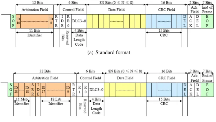
-access to the bus. A minimal communication profile of CAN consists of three layers: the physical layer, the data link layer, and the application layer. The ISO standards have defined the physical layer and data link layer for high-speed applications (1Mbps) and low-speed applications (125Kbps) in ISO 11898 [17] and ISO 11519-2 [18], respectively. CAN conforms to the open systems intercommunication model which is defined in physical layer. A node of CAN systems is defined as the unit which can transmit and receive the messages to and from the CAN bus, respectively. Any node in CAN systems does not play a preponderant role in the protocol. It can connect several devices and share data from other devices by a single pair of wires with the data exchanges between CAN nodes (units) at the same time. A message transmitted in CAN systems has an identifier, or an arbitration, which is unique in the network system and serves two purposes: a priority assignment for the transmission and message filter upon reception. In other words, it controls both bus arbitration and message addressing. It can be utilized for some purposes. Zuberi and Shin have presented the scheduling messages on CAN systems for some real-time applications corresponding to assigning different priorities [19-21]. Cavalieri has proposed a procedure for dynamic assignment of priorities to variables [22]. Tindell et al. have proposed an analysis of response time, or latencies, that takes into account the possibility that transmission errors can occur [23-25]. The relevant real-time requirements can be achieved by this approach. CAN bus is reliable so that all transmitted and received messages are guaranteed. CAN is suitable to provide the cost-effective communication network systems of in-vehicle electronics as an alternative to the expensive and cumbersome wiring looms [26-31]. It also has the potential to be the communication network systems of other applications. Figure 2 shows the configuration of a Data frame. The specific fields include Start of Frame (SOF), Arbitration Field (or Identifier), Control Field, Data Field, Cyclical Redundancy Check (CRC) Field, Acknowledgement (ACK) Field, and End of Frame (EOF). CAN has two formats. They are the standard format (the standard frame, CAN 2.0A) and the extended format (the extended frame, CAN 2.0B). The difference of these two formats is the bit size of the Arbitration Field. The Arbitration Field contains no more than 11-bit and 29-bit identifiers for the standard format and the extended format as illustrated in Figure 2 (a) and Figure 2 (b), respectively. Both of them contain 0 to 8 bytes of data in Data Field of the Data Frames. This communication mechanism is quite often new for those who take the course of CAN system. Bransford et al. who provided a comprehensive survey of researches found that “Helping students develop metacognition – knowledge of how they learn – improves the likelihood of their transferring information learned in one context to another one [11].” The instructor can give a general example to imitate that of CAN bus by the experiences or knowledge of students, especially for those from diverse backgrounds. For instance, the communication mechanism of CAN system is like a crowd of people if only one person can talk at same time. The ears of the people can sense the voice (carrier sense), everyone has a mouth and has the same opportunity to speak (multiple access), everyone can distinguish between one voice or multiple voices (collision detection), and everyone can arbitrate the priority of talkers if everyone has his unique priority of speaking (collision resolution). In order to train students in systematic problem-solving approach and to help them to make sense of new information, the inductive teaching methods of inquiry learning and problem-based learning were adopted in this unit. The questions that may be posed by teacher (teacher inquiry) or students (learner inquiry) will help the instructor to figure out what on earth the students from different disciplines are respectively deficient in. Then the instructor can build up the capability of students in this course appropriately.
4 -B. Hardware Synthesis of CAN Systems
The second unit of the course focuses on the hardware synthesis for the CAN unit. Students learn the communication mechanism of CAN system from the first unit of the course. In order to elevate the students’ interests, this course has assignments of hands-on projects and design problems with practical purpose. That will improve the linkages between classroom and industry. This unit not only fosters the interest in implementation of CAN system but raises the skills of micro controller designs extended to other application for students. Students have to synthesis the hardware of CAN units based on micro control unit (MCU, e.g., 8051), CAN controller (e.g., SJA1000), CAN transceiver (e.g., 82C251). They should study the data sheets of the above components first. Students are confronted with an open-end, ill-structured, and real-world (authentic) problem assigned in this unit for the hardware synthesis. The traditional lecture-based teaching approach is incompatible in this unit. In this course, the instructor has synthesized a pattern unit of CAN system, as shown in Figure 3, as a reference for students. The pattern unit has the basic functions of CAN system to show how CAN bus works. For the communication purpose, at least two of the pattern units should be duplicated with different arbitration, or ID. However, this pattern unit did not show up before students finished their original hardware synthesis. Students can compare their designs with this pattern unit after they have completed their design. They will learn what the shortcomings or excellences in their hardware synthesis after the instructor explains how he/she synthesized this pattern unit. The instructor will help students to develop problem-solving skills in hardware synthesis with worked-example instruction [32, 33]. Port 0 of the MCU is selected to serve as the address and data buses connected to the corresponding pins of the CAN controller. One pin of Port 2 of the MCU acts as chip control connected to chip select pin (CS) of CAN controller. Note that the high byte of the base address of CAN controller in the synthesis of CAN unit depends on Port 2. The pins of ALE, RD, WR, and INT0 of MCU should connect to the corresponding pins of CAN controller. Besides, the TX0 and RX0 pins of CAN controller have to connect to the TXD and RXD pins of the transceiver, respectively. The basic function of CAN is constructed based on the MCU. It seems very intuitive. Students may not be familiar with the design of MCU, CAN controller, or transceiver although they are interested in the hardware synthesis. In learning cycle, students work through sequences of activities involving complementary thinking and problem-solving approaches from some hands-on practices. The instructor should teach around the learning cycle including “why?”, “what?”, “how?”, and “what if?” [15, 34].
C. Software Programming and System Engineering of CAN Systems
The third unit of the course aims at the software functions of each unit in CAN system. The software is developed by Keil-C. Students can learn how to implement the functions of a CAN node (unit) by software programming. The variables for CAN controller declared as “XBYTE” in Keil-C can facilitate the software synthesis for CAN node (unit) since the pins of Port 0, Port 2 (control pin connected to the pin of chip selected in CAN controller), ALE, RD, WR, and INT0 of MCU have connected to the corresponding pins of CAN controller pertinently. The base address of the CAN controller can be specified according to the control pin of Port 2 in MCU. The MCU can access the data on the CAN Bus from the CAN controller and its transceiver. This unit of the course applies the project-based learning approach since the software for MCU is quite simple but the assignments of functions for each CAN unit are more complicated. The instructor in this unit should be familiar with and have a great deal of
5
-experience in both the hardware synthesis and the software programming of MCU. The project-based learning emphasizes the applications and integrations of the previous acquired knowledge while the problem-based learning help students acquiring the knowledge [15]. In this unit, students have an assignment to carry out the task in which the CAN system should act as the traditional network system, i.e., the learning method is the problem-based learning followed by more open-ended project-based learning. Although every node (unit) in CAN system is the same in the hardware synthesis, each has its own functions such as the arbitration (ID), mask, filter, etc., which are assigned by software. The arbitrary is unique for each CAN node in the CAN system. Otherwise, there will be some communication troubles in the CAN system. In this unit, students have to learn how to map out the specified functions in the automotive electronics learning board such as the protocol of data transmission between CAN units, event/time triggers of CAN units, the designation of arbitration (ID), mask, and filter for CAN units, the assignments of sensor and control signals, etc. The training for system analysis and the system engineering is important for novices in engineering. The course of CAN system is applicable to the inexperienced students in system synthesis since the node number of the CAN system assigned in this course is no more than 6. The task in this assigned project can appropriately help students to build up the capability of system engineers and to accumulate the experiences of solving real-world problems. Furthermore, the task will wean the students away from dependence on instructors as the primary source of
required knowledge and technology supports. It may assist student in becoming self-learners as well.
3. Evaluation
In order to evaluate the effectiveness of the cocktail teaching methods for different units in the course of the CAN system, we had to compare the results of the post-test with those of the pre-test. The questionnaire completed by the students can provide the qualitative feedback of this course. The pre-test was done in the first day of the course and the post-test was done after the last day of the course. We have two groups of students. One is the experimental group that had 3 students taking the course and the other is the compared group that had 9 students who did not take the course.
Table 1 shows the change in proportions of students getting correct answers in different categories of the course for the experimental group and the compared group in (a) and (b), respectively. In Table 1(a), all the students have taken relevant courses of MCU. Since there are only 3 questions in those questionnaires, the students did not have significant improvement in Category B (Hardware Synthesis of CAN Systems). However, there seemed to be a crucial improvements for the students in Category A (Communication Protocol of CAN) and Categrary C (Software and System Engineering of CAN Systems) for the experimental group. In Table 1(b), the students have no significant difference in the compared group. This meta-analysis may be insufficient to support the teaching and learning methods for the course of CAN system. However, we have found that students made great progress not only in domain knowledge of CAN systems but also in capability of discussing questions and solving problems about the MCU.
4. Conclusion
We developed the automotive electronic training board which has two modes including traditional and CAN networks with a toggle. This training board can confront the students with the authentic
6
-(real-world) problems in this course. A pattern unit of CAN system has been synthesis before the course.
Students can learn what the shortcomings or excellences in their hardware synthesis by comparing the hardware synthesized by themselves with this pattern unit of CAN. The instructors who educated students in this course should be familiar with CAN system, the hardware design and software program of MCU, and some inductive teaching methods. From our experiences, the inductive teaching and learning methods can apply to some engineering education pertinently. It depends on the contents in the course. In the first unit of the CAN course, the inductive teaching methods of inquiry learning and problem-based learning are suggested. In the other units, we recommend the hybrid approaches including problem-based and project-based learning.
Although the evaluation of the pedagogy was first done in this course, the teaching approaches were adopted in the course of CAN systems for many years. Some of the students that took the course of CAN systems have been with some firms of automotive electronic related industry. They are not novices in automotive network any more, especially for CAN systems. They are expert-like practitioners after graduation. That motivated this study of the teaching and learning approach. We will continue the meta-study the teaching and learning methods for the course of CAN system.
Acknowledgement
This research work is supported by National Science Council under Grand NSC 98-2511-S-018-007.
References
[1] Navet, N., Y. Song, F. Simonot-Lion, and C. Wilwert," Trends in Automotive Communication Systems", Proceedings of the IEEE Vol. 93, No. 6, 2005, pp. 1204-1223.
[2] Chavez, M.M.," Learner's Perspectives of Authenticity", American Council on the Teaching of Foreign Languages, 1994.
[3] Koschmann, T.D., A.C. Myers, P.J. Feltovich, and H.S. Barrow," Using Technology to Assist in Realizing Effective Learning and Instruction", Journal of the Learning Sciences Vol. 3, 1994, pp. 227-264.
[4] Newmann, F.M., H.M. Marks, and A. Gamoran," Authentic Pedagogue and Student Performance", American Journal of Education Vol. 104, No. 4, 1996, pp. 280-312.
[5] Hale, J.C., and H.L. Sellars," Historical Data Recording for Process Computers", Chemical Engineering Progress Vol. 77, No. 11, 1981, pp. 38-43.
[6] Bonert, R.," Interactive Simulation of Dynamic Systems on a Personal Computer to Support Teaching", IEEE Transactions on Power Systems Vol. 4, No. 1, 1989, pp. 380-383.
[7] Wiesner, T.F., and W. Lan," Comparison of Student Learning in Physical and Simulated Unit Operations Experiments", Journal of Engineering Education Vol. 93, No. 3, 2004, pp. 195-204.
[8] Okamura, A.M., C. Richard, and M.R. Cutkosky," Feeling is Believing: Using a Force-Feedback Joystick to Teach Dynamic Systems", Journal of Engineering Education Vol. 91, No. 3, 2002, pp. 345-349.
[9] Fraser, D.M., R. Pillay, L. Tjatindi, and J.M. Case," Enhancing the Learning of Fluid Mechanics Using Computer Simulations", Journal of Engineering Education Vol. 96, No. 4, 2007, pp. 381-388. [10]Chi, M.T.H., R. Glaser, and M.J. Farr, The Nature of Expertise, Hillsdale, N.J.: L. Erlbaum Associates,
7
-[11] Bransford, J.D., A.L. Brown, and R.R. Cocking, How People Learn: Brain, Mind, Experience, and School, Expanded ed., Washington D.C.: National Academy Press, 2000.
[12] Adams, R., J. Turns, and C.J. Atman, "What Could Design Learning Look Like?", Design Thinking Research Symposium VI, Sydney, Australia, 2003.
[13] Atman, C.J., R.S. Adams, M.E. Cardella, J. Turns, S. Mosborg, and J. Saleem," Engineering Design Processes:A Comparison of Students and Expert Practitioners", Jourmal of Engineering Education Vol. 96, No. 4, 2007, pp. 359-379.
[14] Marton, F., and R. Saljo, The Experiences of Learning, 2nd ed. ed., Edinburgh: Scottish Academic Press, 1997.
[15] Prince, M.J., and R.M. Felder," Inductive Teaching and Learning
Methods:Definitions,Comparisons,and Research Bases", Jourmal of Engineering Education Vol. 95, No. 2, 2006, pp. 123-138.
[16] Johansson, K., M. Törngren, and L. Nielsen, Handbook of Networked and Embedded Control Systems, Boston, MA: Birkhäuser, 2005.
[17] "Road Vehicles - Interchange of Digital Information: Controller Area Network for High Speed Communication": ISO-11898, 1994.
[18] "Road Vehicles - Low Speed Series Data Communication, Part 2: Low Speed Controller Area Network": ISO 11519-2, 1994.
[19] Zuberi, K.M., and K.G. Shin, "Non-Preemptive Scheduling of Messages on Controller Area Network for Real-Time Control Applications", in Proceedings of Real-Time Technology and Applications symposium, 1995, pp. 240-249.
[20] Zuberi, K.M., and K.G. Shin," Scheduling Messages on Controller Area Network for Real-Time CIM Applications", IEEE Transactions on Robotics and Automation Vol. 13, Apr. 1997, pp. 310-314. [21] Zuberi, K.M., and K.G. Shin," Design and Implementation of Efficient Message Scheduling for
Control Area Network", IEEE Transactions on Computers Vol. 49, 2000, pp. 182-188.
[22] Cavalieri, S.," Meeting real-time constraints in CAN", IEEE Transactions on Industrial Informatics Vol. 1, 1997, pp. 310-314.
[23] Tindell, K.W., and A. Burns, "Guaranteed Message Latencies for Distributed Safety-Critical Hard Real-Time Control Networks", Technical Report YCS 229: Department of Computer Science, University of York, York, U.K., 1994.
[24] Tindell, K.W., H. Hamsson, and A.J. Wellings, "Analysing real-time communications: controller area network (CAN)", in Proceedings of the 15th Real-Time Systems Symposium (RTSS’94), 1994, pp. 259-263.
[25] Tindell, K.W., H. Hamsson, and A.J. Wellings," Calculating controller area network (CAN) messages response times", Control Engineering Practice Vol. 3, 1995, pp. 1163-1169.
[26] Schill, J.," An overview of the CAN protocol", Embedded System Programming Vol. 10, 1997, pp. 46-62.
[27] Lawrenz, W., CAN System Engineering: From Theory to Practical Applications, New York: Spring-Verlag, 1997.
[28] Navet, N.," Controller area network: CANs use within automobiles", IEEE Potentials Vol. 17, 1999, pp. 12-14.
8
-[29] Wang, X., C. Chen, and H. Ding, "The Application of Controller Area Network on Vehicle", in Proceedings of the IEEE International Vehicle Electronics Conference, 1999 (IVEC’99), 1999, pp. 455-458.
[30] Etschberger, K., Controller Area Network, Germany: IXXAT Press, 2001.
[31] Chaari, L., N. Masmoudi, and L. Kamoun," Electronic Control in Electric Vehicle based on CAN network", IEEE Conference on Systems, Man and Cybernetics Vol. 7, 2002, pp. 4-7.
[32] Paas, F., and T. vanGog," Special Issue on Recent Worked Examples Research: Decreasing Extraneous and Increasing Germane Cognitive Load to Foster Learning and Transfer", Learning and Instruction Vol. 16, No. 1, 2006, pp. 87-91.
[33] Moreno, R., M. Reisslein, and G. Ozogul," Optimizing Worked-Example Instruction in Electrical Engineering: The Role of Fading and Feedback during Problem-Solving Practice", Journal of Engineering Education Vol. 98, No. 1, 2009, pp. 83.
[34] Felder, R.M.," Matters of style", ASEE Prism Vol. 6, No. 4, 1996, pp. 18-23.
Table 1. Comparison of results per category. (a) The experimental group.
% of students passed
Course Unit Category Question No. Pre-test Post-test Shift
A. Communication Protocol of CAN 1,2,3,4,5,6,7,9 54.2 95.8 41.7
B. Hardware Synthesis of CAN Systems 12,13,14 100.0 100.0 0.0
C. Software and System Engineering of CAN Systems 8,10,11,15 50.0 83.3 33.3
(b) The compared group.
% of students passed
Course Unit Category Question No. Pre-test Post-test Shift
A. Communication Protocol of CAN 1,2,3,4,5,6,7,9 22.8 8.1 -14.7
B. Hardware Synthesis of CAN Systems 12,13,14 19.6 17.6 -2.0
9
-Figure 1. The automotive electronics learning board with a network toggle switch.
(a) Standard format
(b) Extended format
10
-Figure 3. Hardware of the pattern unit for CAN system.
國科會補助專題研究計畫成果報告自評表
請就研究內容與原計畫相符程度、達成預期目標情況、研究成果之學術或應用價
值(簡要敘述成果所代表之意義、價值、影響或進一步發展之可能性)
、是否適
合在學術期刊發表或申請專利、主要發現或其他有關價值等,作一綜合評估。
1. 請就研究內容與原計畫相符程度、達成預期目標情況作一綜合評估
□
ˇ
達成目標
□ 未達成目標(請說明,以 100 字為限)
□ 實驗失敗
□ 因故實驗中斷
□ 其他原因
說明:
2. 研究成果在學術期刊發表或申請專利等情形:
論文:□已發表
□
ˇ
未發表之文稿□撰寫中 □無
專利:□已獲得 □申請中
□
ˇ
無
技轉:□已技轉 □洽談中
□
ˇ
無
其他:(以 100 字為限)
3. 請依學術成就、技術創新、社會影響等方面,評估研究成果之學術或應用價
值(簡要敘述成果所代表之意義、價值、影響或進一步發展之可能性)(以
500 字為限)
本計畫為研究「控制器區域網路(CAN)系統」課程教學法之效果,就車輛網路系統之 CAN 系統相關課程及其教學法之研究實為國內第一次,而時值車輛科技工業革命的關鍵 時刻,諸如節能、減碳、環保、綠能等之要求及其科技之發展,車輛電子更是日新月異, 而車輛網路系統更是不可或缺之要角,學生於進入職場前之學習與訓練,應是未來車輛科 技工業進步與競爭之重要因素,因此如何有效地訓練及教導學生具備進入職場前之 CAN 系統相關知識及技能,乃為本研究計畫之目標,本研究中針對不同單元或內容,提出引導 式混合教學法,諸如詢問式學習法(Inquiry Learning)、問題基礎式學習法(Problem-Based Learning)、專案基礎式學習法(Project-Based Learning)等,並經由前測及後測之評估,修課 學生具顯著學習成效,因此該教學法可供 CAN 系統相關課程授課教師參考,唯取樣數仍 顯不足,更待未來累積更多資料量,做更嚴謹之成效分析。出席國際學術會議心得報告
計畫編號 NSC 98-2511-S-018 -007 計畫名稱 車輛網路系統之嵌入式微處理器實驗教材發展之研究 出國人員姓名 服務機關及職稱 楊介仙 國立彰化師範大學 車輛科技研究所 副教授 會議時間地點 2010.04.05~11 美國佛州奧蘭多市 會議名稱 (中文) 2010 複雜系統研究、資訊學及電腦控制學等國際研討會 (英文) The International Multi-Conference on Complexity, Informatics andCybernetics (IMCIC 2010)
發表論文題目 A Feasible Approach to the Evaluation of the Tractions of Vehicle Wheels Driven by DC Motors (如附件一)
一、參加會議經過
4 月 6 日美國當地時間上午 08:00 抵達佛州奧蘭多市國際機場,逕赴該研討會之舉行 地點-奧蘭多雙樹旅館(Doubletree Resort Orlando),因介仙已完成線上註冊,因此僅需完 成報到及提領相關會議資料等,由於介仙亦擔任計算機科學及工程暨控制系統、技術及 應 用 分 項 會 議 (Computer Science & Engineering / Control Systems, Technologies & Applications)第一共同主持人(Co-Chairman, 如附件二第 10 頁),因此亦須完成主持人報 到及領取共同主持人應注意事項資料。
2010 複 雜 系 統 研 究 、 資 訊 學 及 電 腦 控 制 學 等 國 際 研 討 會 (The International
Multi-Conference on Complexity, Informatics and Cybernetics, IMCIC 2010)為國際資訊學暨系統 學學會(International Institute of Informatics and Systemics, IIIS)主辦之研討會,主要目的為透過 學術論文發表的方式,聚集專家及學者,經由研討複雜系統、資訊學及電腦控制學等三 項研究成果的討論,促進不同學術或研究領域間的專家及學者之交流與互動,亦促使可 能不同學術研究間之合作、不同領域間相互激盪及創造相類似之產物所需的人類智慧結 晶,因此,正式之學科導向的分項會議於焉形成,IMCIC 2010 之研討會大致分為二類, 一為 IMCIC 2010 之主題分項會議,另一為廣泛主題類之分項會議,IMCIC 2010 之研討 會冀望於各不同學科及研究透過論文發表及非正式相互間的對話及討論而獲得相互間的 技術交流,達到不同領域或學科間潛在可能之合作研究。 介仙於IMCIC 2010 研討會中發表一篇論文,論文題目如上表格所示,發表時間為 4
月 8 日上午 9:45 至 12:00,由於與 James P. Buckley 教授(USA)共同主持「計算機科學及 工程暨控制系統、技術及應用」分項會議,介仙與 Buckley 先生協商後,輪流引介該分 項會議論文發表主講人及其背景,並讓與會者認識共同主持人之一來自中華民國台灣。
二、與會心得
國大陸,再者為我國,一向在東亞及東南亞舉辦研討會之日本、韓國等所佔比率較少, 或因東北亞到美國東部較遠之故,或因語言的隔閡之故,但以介仙參與一些東方的學術 研討會的經驗觀之,日本、韓國之論文報告大多由學生報告,雖說日韓學生(即便是教授) 之英語說得能力不佳,聽得能力更是乏善可陳,但日韓學生敢於嘗試超過自己能力的挑 戰,就具保守性格的東方民族而言,實是難能可貴,足堪國內學生學習其學習態度,學 習總是潛移默化,一蹴可及實是不易的,而嘗試超過自己能力的學習,卻是進步的原動 力,饒是如此,真的要日本、韓國等國在英語國家以英文發表論文,確實是為難這些性 格保守的東方學生了。另一方面,中國大陸近幾年在國際學術研討會議均積極參與,即 便遠在美國東岸的國際學術研討會,亦不遑多讓,勘為我國學術研究參與國際相關學術 會議之警惕。 國內學生說起英語畏首畏尾,能力絕非低於日韓學生,但不敢勇於嘗試,我消彼長, 如此循環,國家競爭力將每下愈況,另一原因則是學生(特別是碩士生)參與國際研討會 之經費籌措不易,導致學生發表論文之意願降低,就韓國而言,由於韓國政府大力發展 科技及人才培育,碩、博士學生發表國際會議論文即給予補助,因此直接鼓勵碩、博士 學生積極參與國際學術會議,而東亞之國際學術會議參與之經費不多,且各國之英語能 力平平,可建立國內學生之自信,再逐步走向國際,因此介仙建議應鼓勵一般學生參與 東亞之國際學術會議,應是國內碩、博士學生英語聽說能力之學習及初試啼聲之場所, 而語言能力較佳的學生則鼓勵其參與英語國家之國際學術研討會。吾人實不願見國家競 爭力逐年下降,因此常鼓勵學生出國參與國際學術會議並報告論文,以培育具國際視野 之人才。 三、建議 近幾年來,國人參與國際學術研討會的人數正相對地逐年遞減中,早年幾乎都是國 人的人數比率居多,曾幾何時,日本、韓國,乃至大陸的參與人數比率已迎頭趕上,並 早已超越國人參與人數比率,常此以往,國人將會被國際學術研討會邊緣化,因此應鼓 勵並支持國內研究人員積極參與國際學術研討會,積極且不排斥擔任分項會議主持人, 增加中華民國台灣之暴光度,並培育具國際視野之人才,建議應給予參與的學生(包括大 學生及碩士生等)適當之經費補助,以資鼓勵。 四、攜回資料名稱及內容 研討會論文光碟一片、會議議程暨紀錄一本。
A Feasible Approach to the Evaluation of the Tractions
of Vehicle Wheels Driven by DC Motors
Jieh-Shian Young
Institute of Vehicle Engineering, National Changhua University of Education Changhua, Taiwan, R.O.C.
and
Sheng-You Wu
Institute of Vehicle Engineering, National Changhua University of Education Changhua, Taiwan, R.O.C.
ABSTRACT
This paper proposes an approach to evaluate the tractions of the vehicle wheels driven by DC motors directly. The database of the DC motors, such as current versus voltage, PWM and loading, has to be built through the automatic data acquisition system. Instead of the slip ratio measurements, the evaluation of the tractions can provide the force information of the traction wheels by using the interpolations of the database with applied voltages, PWM signals and measured currents of the DC motors. In order to verify the feasibility of this approach, the automatic data acquisition system has been implemented for a single traction wheel including the database establishments of DC motors. This system should assure that the commands and data transmitted are always correct. The details of the units in the system are discussed such as initializations of units, flow chart of PWM command transmissions, etc. The motor loadings are also evaluated with specific applied voltages, PWM values and measured currents. The result shows that it is feasible to evaluate the loadings through the interpolations of the database of the DC motor.
Keywords: Communication protocol, DC motors, pulse-width
modulation (PWM), slip ratio, traction forces.
1. INTRODUCTION
The global environmental protection becomes one of the most significant issues for the studies and developments of new alternative products, the vehicles of the transportation especially. For instance, the electric vehicle (EV) driven by direct current (DC) motor is a feasible and potential candidate for the future transportation vehicles. Comparing with traditional vehicle (internal combustion engine vehicle, ICV), EV does not need any additional costly hardware to achieve the engine control, brake control, or mission control [1]. For example, antilock braking systems (ABS) of vehicles have received a great concern and become one of the most common automotive technologies [2-9]. The aim of ABS is to control the wheel slip so as to attain the optimum values that can provide maximum negative traction force during heavy braking and maintain the sufficient stability and steering ability. For most road surfaces, the maximum tire-road adhesive coefficient is at the slip ratio ranged from 0.1 to 0.3 [10]. When a vehicle
brakes, the ABS will prevent the wheels from locking and keep the wheel slip ratio within a specific range. Most ABS control will retain the wheel slip ratio at a value 0.2 as compromise [2]. However, the wheel slip ratio is difficult to be measured from the speed of the vehicle. In addition, the optimal wheel slip ratios highly depend on the different road surfaces and road conditions. Fujimoto and Fujii [11] patented their slip ratio estimating device that can measure the slip ratio without using the speed of a vehicle body and can be utilized by the so-called the slip ration control device. Nakao also proposed a method and program for judging road surface conditions [12], This method and program can determine the slip ratio from wheel rotation speed.
The purpose of the measurement of slip ratio in ABS is to evaluate the forces between the tire and the road surface. The measurement of slip ratio is still a tough issue for ICVs since the exact speed of a vehicle is difficult to measure although there are some feasible ways to estimate the slip ratio[11, 12]. On account of the rapid improvements and developments in motors and batteries, the EV has been the most potential alternative to the traditional vehicles. In addition, EVs have attracted great interests as a feasible solution against the problems of environment protection and energy depletion. One of the advantages of the EV is that its motor torques can be measured easily [9]. Instead of the wheel slip ratio measurements, the traction evaluations of the in-wheel motors can directly provide the information of the tractions of the vehicle’s wheels driven by motors. They can be utilized to stabilize the steering of the vehicles traveling into other road surfaces such as a wet or slippery road surfaces. Accordingly, this paper proposes an approach to measuring the tractions of a single wheel based on the database of the permanent magnet (PM) direct current (DC) motors. We set up an automatic data acquisition system that can collect the database for a DC motor. The traction can be evaluated by interpolations from the applied voltages, PWM values, and measured currents of the DC motor. The result shows this approach is feasible.
Section 2 briefly discusses the force balance and the kinematics of a vehicle. Some related characteristics of PM DC motors are also addressed in this section. Section 3 states the construction of the automatic data acquisition system. In addition, the implementation of the system is also described in this section. The details of the data acquisition system are given in Section 4 including the flow charts of the initialization and command transmissions. Conclusions are drawn in
Section 5.
2. FORCE BALANCE AND KINEMATICS OF VEHICLE
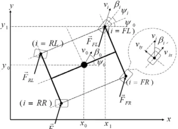
Recently, the studies of the relations between friction coefficient and slip ratio, so called the μ-λ curves (friction coefficient versus slip ratio), become one of main streams in the vehicle stability control such as slip ratio estimation, control of ABS, etc [11-13]. In Figure 1,
i
ω and respectively denote the rolling angular velocity and radius of the specified wheel indexed i. The slip ratio is defined as follows.
i r ( ) ( ) ⎩ ⎨ ⎧ < − > − = ), ( / ); ( / ix i i ix ix i i ix i i i i ix i i i v r v v r v r r v r s ω ω ω ω ω
where is ranged from -1 to 1. means the vehicle gains the traction from corresponding wheel, while as the corresponding wheel is in brake situation. The slip ratio is regarded as one of the most significant parameters for the quality of vehicle steering control. There are at least two issues to be concerned. One is that the road surfaces are manifold and tires are, too. It is hard to characterize all the conditions between tires and road surfaces. The other is that the speed of the vehicle is difficult to be measured actually. That is, evaluating the slip ratio is quite impossible for ICV in real time. However, the aims of the sensors to measure the slip ratio, of algorithms to evaluate the slip ratio, or of the estimations of the slip ratio are to provide the information of traction forces for wheels. Furthermore, the dynamics and kinematics of a vehicle can be analyzed if the forces of the traction wheels are known.
i s si >0 0 < i s
(a) Side view. (b) Top view. Figure 1. Kinematic model of a wheel.
By the Newton’s Law, the force balances of the traction wheels govern the dynamics and kinematics for a vehicle as shown in Figure 2. The dynamics of the vehicle highly depends on the traction forces provided by the wheels such positions, velocities, and accelerations of linear and rotational motions. In case the forces of all wheels are well evaluated, the measurements of slip ratio are not necessary and the steering capability and stability of vehicles can be achieved intuitively. So far, EV is entirely driven by the electrical motors (such as PM DC motors) whose torques generated can be controlled much more quickly and precisely than those of internal combustion engines [14]. For instance, the relationship between torque and current is very simple for a PM DC motor. It can be expressed in the following equation.
A KI T = ,
where T is the mechanical torque, K is the motor constant, and is the armature current. The torque can not only drive its armature and shaft but also provide the applied loading torques
and result in the angular acceleration of wheel. The torques from PM DC motor can be evaluated without any additional sensors if the database of this PM DC motor is established such as the current-PWM-torque data with specified applied voltage. That is, the tractions can be evaluated from interpolations with the PWMs, currents, and voltages applied to the motor.
A I
Figure 2. Kinematics and Force model of a vehicle.
3. THE AUTOMATIC DATA ACQUISITION SYSTEM OF TARGET DC MOTOR
Motors are classified as either alternative current (AC) or DC, which depends on the type of power applied to them. DC motors have well speed-control capability while AC motors generally run at a fixed speed determined by the frequency of power. The field flux of a PM motor, a kind of DC motor, retains constant regardless of speed. This fact makes for a very linear torque-speed curve for this kind of motors. This is profitable in control applications because of its simplicity in control. In addition, PM DC motor will become a feasible and potential candidate of the EV traction wheel drivers. In steady of analog-drive system of a DC motor control, the pulse-width modulation (PWM) is a completely different approach to controlling the torque and speed of a DC motor. It is digital inherently and can be controlled from a computer with a single pin of micro control unit such as single chip, etc The speed of a DC motor depends on the percentage duty cycles of PWM signals. The armature current of a DC motor will increase as the torque increases. The force information for a DC motor can be obtained from the relations between the percentage PWMs, currents, and voltages applied to this DC motor. It is feasible to develop the force evaluation algorithm from those above data.
In general, the characteristics of a PM DC motor are time variant although they are not quite different during a short interval. The database of a PM DC motor will become more reliable if it is updated in short periods when the vehicle needs maintenance services. Therefore, a quick data acquisition system for motors is indispensable. In this paper, we construct an automatic data acquisition system for PM DC motors. The system will facilitate the data acquisitions for PM DC motors. Figure 3 shows the function block diagram of the automatic data acquisition system for PM DC motors. PWM commands and the torque settings of loadings can be generated by the dedicated program in personal computer (PC) sequentially and automatically. When the motor control unit (MCU) receives
PWM commands from PC, it will follow these commands and send the corresponding PWM signals to drive the motor in appropriate actions with power supply. MCU also measures the voltages and the currents applied to the motor and the rotation speeds (revolutions per minutes, RPM) of the motor. The other motor which can be set by PC and is able to be controlled in order to keep constant torques provides the specified torque loadings. In addition, the torque sensor feeds back the measured torques to PC. The data acquisition unit can acquire and save the data of PWM commands, voltages, currents, RPMs, and torques as well as establish a database of the measured motor.
Figure 5. The characteristic curves for IG42GM Motor in 12-V[16].
Figure 3. The function block diagram of the data acquisition system for DC motors.
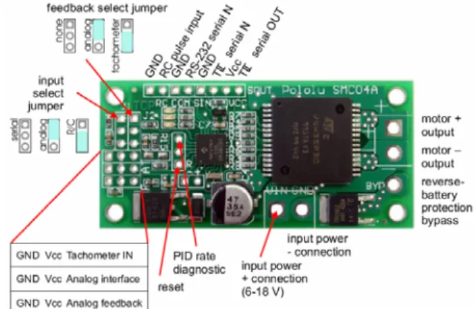
Figure 6. The motor controller (Pololu SMCO4A)[17]. A low-cost experiment test bed is employed so as to verify the
feasibility of the proposed approach. The test bed includes a personal computer (PC) as the data acquisition unit and the command generator with a dedicated program, a MCU (as shown in Figure 4) as the motor control unit, a digital tachometer to measure the RPM of motor, a PM DC Motor with its stand and controller, a current sensor chip (INA138)[15], and the test weights. This test bed utilizes a PM DC motor (IG42GM Motor)[16] and its motor controller (Pololu SMCO4A)[17] as show as Figure 5 and Figure 6, respectively. This motor is used to simulate the motor of the EV traction wheels although it provides a small maximal torque. Some appropriate weights ranged from 0.2-kg to 2-kg are hung on a 5-cm radius pulley which is mounted on the motor shaft. Substituting the motor for constant torque rotation and torque sensor, the weights simulate the loadings, or tractions, on the motor though the friction coefficient between the pulley and the rope is unknown. The loadings could be proportional to the weights. That is, the database of the motor for the loadings, or tractions, will be those proportional indices instead of real loadings. Besides, the friction coefficient may be varying a little in operation. However, it will not cause any significant problem because of the light weights.
Figure 7 shows the implementation of the automatic data acquisition system test bed of the PM DC motor. The dedicated program in PC can automatically generate the PWM commands sequentially and transmit these commands to MCU which can transfer these commands to corresponding PWM signals. The motor controller mounted on the MCU print circuit board can receive the PWM signals via its TTL serial input and drive the motor at specified speeds according to the PWM signals. The current sensor and the digital tachometer measure the applied currents of the motor controller and the RPMs of the motor rotation speed, respectively, for different loadings, different PWM signals, and different applied voltages. The analog signals of the applied currents measured can be converted into digital signals by the analog to digital (A/D) converter embedded in the micro control unit. MCU can receive the digital RPM signals via series port, or RS232, through its series port (RS232). MCU will also transmit the data of the currents and RPMs to PC with the specified weights after the currents settle to steady states. PC acquires these data and automatically sends another PWM command to MCU in order to acquire another corresponding data from the target PM DC motor until the full range of the specified PWM signals is fulfilled. The RPMs of the motor highly depend on the PWM signals. They are hardly affected by different loadings. Therefore, we take down the values of applied currents, PWMs, and torques as database while the corresponding values of RPM are as reference. The mesh diagram of the database which is measured for the PM DC motor by the automatic data acquisition system test bed is illustrated in Figure 8 with 12-V applied voltage. The unknown loading hung on the pulley of the motor can be evaluated from the database by interpolation. For instance, an unknown weight is applied while the percentage PWM signal and the applied current measured are 63% and 0.7666-A, respectively. Then, the weight can be evaluated as 0.8778-kg through interpolation from the PM DC motor database.
Figure 4. The motor control unit (MCU) for the data acquisition system.
(a) Top view of the test bed. (b) Front view of the test bed.
(c) The main program in PC.
Figure 7. The automatic data acquisition system test bed of the DC motor.
Figure 8. The sketch of Current versus PWM (%) and Loading (Kg) for IG42GM PM DC Motor.
4. THE DETAILS OF THE AUTOMATIC DATA ACQUISITION SYSTEM
The automatic data acquisition system includes two main units. One is the PC (with the dedicated program) which generates the PWM commands and saves the measured corresponding data of the target motor. The other is the MCU which receives the PWM commands, transfers the PWM commands to the compactable PWM signals to control the target motor, transmits the measured data to PC. The communication protocol between these two units becomes more significant. We adopt the shake-hand mechanism so that the data acquisition system can work without considering the order of turning on these two units. In addition, this system can measure the corresponding data automatically and sequentially by the appropriate commands of the motor. The brief logic of communication protocol will address as follows.
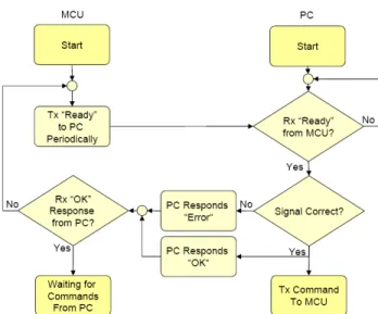
Figure 9 shows the flow chart of the communication protocol as these two units are initialized. In this figure, MCU transmits “Ready” signal to PC periodically until it receives the “OK”
signal from PC when PC is on. The periodical transmission is used to prevent the data passed errors when PC is not ready to receive any signal. MCU is ready to receive any command form PC as long as it receives “OK” signal but “Error”. PC waits for the “Ready” signal from MCU as it is initialized. Besides, it will check whether the signal is correct. If the signal is incorrect, PC will respond “Error” signal to MCU. Otherwise, PC will respond “OK” signal to MCU and will be ready to transmit other commands to MCU.
Figure 9. The flow chart of the communication protocol in
system initialization.
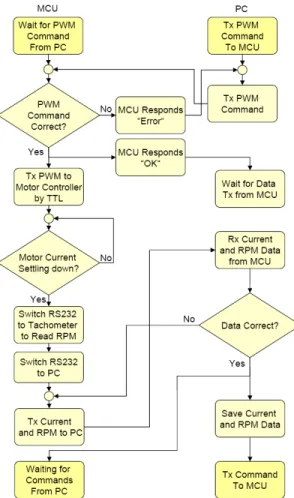
The procedure of data measurements can be undertaken by the data acquisition system with the PWM commands transmissions after the initialization of PC and MCU. However, this acquisition system should assure that the transmissions of the measured data are always correct. The shake-hand mechanism has been also adopted in the data acquisition system so as to prevent the measured data from the error transmissions. Figure 10 shows the flow chart of the communication protocol in commands transmissions from PC and the actions as well as the reactions between PC and MCU. First of all, PC transmits the appropriate PWM command to MCU and waits for the response from MCU. If the PWM command is correctly received by MCU, MCU will transmit “OK” response to PC, decode the PWM command and send the corresponding PWM signals to the motor controller via the TTL input of the motor controller. Otherwise, PC will receive “Error” response from MCU. In case that PC receives “Error” response from MCU, it will transmit the same PWM command again until it receives “OK” response from MCU. Then, PC will wait for the measured data from MCU. In the meantime, MCU will measure the applied current of the motor from the current sensor after it sends the PWM command to motor controller. When the current settles down, MCU switches the series communication, or RS232, to the digital tachometer in order to read the measured RPM of the motor since MCU has only one series communication port. MCU switches the RS232 to PC if the RPM data are acquired from the digital tachometer. Then, MCU transmits the data including the current and RPM of the motor to PC. PC will checks whether the current and RPM of the motor are correct. If no, PC will request MCU to send the same data again until these data transmitted are correct. If yes, PC will save these data and transmit another PWM command if necessary.
The objective of the automatic data acquisition system for PM DC motors is to facilitate the procedure to acquire the data of traction motors of vehicles so that the updated database can be utilized in the steering control, ABS, etc. For instance, we can utilize these databases of the motors to simulate the dynamics of a vehicle with this kind of the traction motors, to control the steering of this vehicle, or to equip the ABS for the vehicle with the forces feedback.
Figure 10. The flow chart of the communication protocol between PC and MCU.
5. CONCLUSIONS
The result shows the forces of the traction wheels between tires and road surface can be evaluated based on the database of the specified motors. It is independent of what kinds of tires or road surfaces they are. In addition, the slip ratio measurements for the traction wheels are not necessary since the force information can be evaluated by the interpolations of the database directly. However, this approach is not possible for the vehicles with internal combustion engine but for EVs with traction PM DC motors on account of the quick responses of applied currents, voltages, and PWMs for PM DC motors. Furthermore, the steering capability and stability of vehicles can be improved by feedback or logical control intuitively. We also provided the configuration of the automatic data acquisition system in order to facilitate the establishments of the database for PM DC motors. The system will make rapid upgrades of database for traction wheels of vehicles feasible in the near future. The communication protocols between PC
(with dedicated program) and MCU can assure the corrections of the command transmissions. We also implemented a low-cost experiment test bed to verify the feasibility of the concept. It shows that this approach can be implemented.
ACKNOWLEDGEMENT
This research work is supported by National Science Council under Grand NSC 98-2511-S-018-007.
9. REFERENCES
[1] Y. Hori, Y. Toyoda, and Y. Tsuruoka, "Traction Control of Electric Vehicle: Basic Experimental Results Using the Test EV“UOT Electric March”," IEEE Transactions on Industry Applications, vol. 34, pp. 1131-1138 1998.
[2] Y. S. Kueon and J. S. Bedi, "Fuzzy-seural-sliding mode controller and its applications to the vehicle anti-lock braking systems," in
Proceedings of IEEE/IAS Conference on Industrial Automation and Control: Emerging Technologies, 1995, pp. 391-398.
[3] P. Khatun, C. M. Bingham, P. H. Mellor, and N. Schofield, "Discrete-time ABS/TC test facility for electric vehicles," in
Proceedings EVS-16, China, 1999.
[4] P. Khatun, C. M. Bingham, and P. H. Mellor, "Comparison of control methods for electric vehicle antilock braking/traction control system," in Proceedings at the SAE 2001 World Congress, Detroit, MI, 2001, p. Paper 2001 010 596.
[5] X. He and J. W. Hodgson, "Modeling and Simulation for Hybrid Electric Vehicles—Part I: Modeling," IEEE Transactions on
Intelligent Transportation Systems, vol. 3, pp. 235-243, 2002.
[6] X. He and J. W. Hodgson, "Modeling and Simulation for Hybrid Electric Vehicles—Part II: Simulation," IEEE Transactions on
Intelligent Transportation Systems, vol. 3, pp. 244-251, 2002.
[7] R. Saeks, C. J. Cox, J. Neidhoefer, P. R. Mays, and J. J. Murray, "Adaptive Control of a Hybrid Electric Vehicle," IEEE
Transactions on Intelligent Transportation Systems, pp. 213-234,
2002.
[8] P. Khatun, C. M. Bingham, N. Schofield, and P. H. Mellor, "Application of Fuzzy Control Algorithms for Electric Vehicle Antilock Braking/Traction Control Systems," IEEE Transactions
on Intelligent Transportation Systems, vol. 52, pp. 1356-1364,
2003.
[9] Y. Hori, "Future Vehicle Driven by Electricity and Control—Research on Four-Wheel-Motored “UOT Electric March II”," IEEE Transactions on Intelligent Transportation
Systems, vol. 51, pp. 954-962, 2004.
[10] A. K. Baker, Vehicle Braking. London: Pentch Press, 1986. [11] H. Fujimoto and K. Fujii, "Slip Ratio Estimating Device and Slip
Ratio Control Device." vol. WO/2008/029524, W. I. P. Organization, Ed. Japan: Yokohama National University 2008. [12] Y. Nakao, "Method for Judging Road Surface Condition and
Device Thereof, and Program for Judging Road Surface Condition." vol. 7,512,473, U. S. Patent, Ed. Japan: Sumitomo Rubber Industries, 2009.
[13] W. Y. Wang, I. H. Li, M. C. Chen, S. F. Su, and S. B. Hsu, "Dynamic Slip Ratio Estimation and Control of Antilock Braking Systems Using an Observer Based Direct Adaptive Fuzzy–Neural Controller," IEEE Transactions on Industrial Electronics, vol. 56, pp. 1746-1756, 2009.
[14] T. Furuya, Y. Toyoda, and Y. Hori, "Implementation of Advanced Adhesion Control for Electric Vehicle," in Proceedings of 1996
4th International Workshop Conference on Advanced Motion Control, 1996, pp. 430-435.
[15] Burr-Brown, High-Side Measurement Current Shunt Monitor: Burr-Brown, 1999.
[16] S. Y. Ye, IG-42 Geared Motor Series. Hsinchu: PlayRobot, 2006. [17] Pololu, High-Power Motor Controller with Feedback User's
Guide (perliminary). Las Vegas: Pololu Robotics and Electronics,
Complexity, Informatics and Cybernetics: IMCIC 2010 The International Multi-Conference on The 16th International Conference on Information Systems Analysis and Synthesis: ISAS 2010 Jointly with The 8th International Conference on Computing, Communications and Control Technologies: CCCT 2010 and
April 6th - 9th, 2010 ~ Orlando, Florida USA.
General Framework and Plenary Keynote Speakers of the Collocated Conferences
Conference Program
TUESDAY, APRIL 06, 2010
(9:00 AM - 12:00 PM ) (1:00 PM - 5:00 PM )
Registration Registration
Florida Bay 1 Florida Bay 1
WEDNESDAY, APRIL 07, 2010
General Joint Plenary Session of all Collocated Conferences (with Plated Breakfast)
7:45 AM - 9:30 AM (Room: Coral A-B)
Registration Registration (8:00 AM - 12:00 PM) (1:00 PM - 5:00 PM) (Room: Florida Bay 1) (Room: Florida Bay 1)
( 9:45 AM - 12:00 PM ) ( 1:00 PM - 3:30 PM ) ( 4:00 PM - 6:30 PM )
Engineering Concepts, Relations and Methodologies I (ICEME)
Complexity I (IMCIC)
Education Research, Theories, Practice, and
Innovations I (ICETI)
Interdisciplinary Education, Distance Education and Open Learning (Virtual Session) (ICETI)
Learning Technologies / The Academic Sector & the ICT (ICETI / ICSIT)
Computer Science and Engineering (IMCIC)
The Academic Sector and the ICT (ICSIT)
Communications & Control Systems / Image Computing (CCCT)
Education, Learning and Training (ICETI)
Informatics I (IMCIC)
Communications & Control Systems, Technologies & Applications (Virtual Session) (CCCT)
Application of Education Technologies / Teaching Support Systems (Virtual Session) (ICETI)
ICT-Based Electronic Data Processing / Information Systems (ISAS / CCCT)
The Private Sector and the ICT (ICSIT)
Impact of Information and Communication Technologies (ICT) on Societies I (ICSIT)
Image, Speech and Signal Computing (Virtual Session) (CCCT)
Technological Development and Innovation I (ICEME)
Disciplinary Research / Meta-Engineering Praxis (ICEME)
Information Systems (Virtual Session) (CCCT)
IMCIC Conversational Meeting
Welcome Reception 7:00 PM - 8:30 PM (Room: Indian-Pacific)
THURSDAY, APRIL 08, 2010
General Joint Plenary Session of all Collocated Conferences (with Plated Breakfast)
7:45 AM - 9:30 AM (Room: Indian)
Registration Registration (8:00 AM - 12:00 PM) (1:00 PM - 5:00 PM) (Room: Florida Bay 1) (Room: Florida Bay 1)
( 9:45 AM - 12:00 PM ) ( 1:00 PM - 3:30 PM ) ( 4:00 PM - 6:30 PM )
Computer Science & Education Research, Theories,
Page 1 of 15 Program
2010/5/18 http://www.iiis2010.org/imcic/Program/html/program-26.htm
Papers Presentation Schedule Engineering / Cybernetics (IMCIC) Practice, and Innovations II (ICETI) Computing / Information Systems and Technologies (CCCT)
Education in STEM / Virtual Classroom & Universities (ICETI) Communications Systems I (CCCT) Complexity II (IMCIC)
Mobile /Wireless Systems, Technologies and Applications (CCCT)
Informatiom Systems and Education (CCCT) 0000007
Computer Science & Engineering / Control Systems, Technologies & Applications (IMCIC) Informatics II (IMCIC) Knowledge Generation, Communication and Management (KGCM)
Energy Storage - Hydrogen Storage, Thermal Storage, Batteries and
Ultracapacitors (ICEME) 0000004
Communication & Network Systems, Technologies & Applications (IMCIC)
The Public Sector and the ICT / ICT on Societies (ICSIT)
Computing
Technologies I (CCCT)
Disciplinary Research (ICEME)
Education: Concepts,
Technologies and Methodologies I (ICETI)
Meta-Engineering Science and Engineering
Philosophy (ICEME)
Information Systems Engineering and Management (Virtual Session) (ISAS)
ICEME Conversational Meeting
FRIDAY, APRIL 09, 2010
General Joint Plenary Session of all Collocated Conferences (with Plated Breakfast)
8:00 AM - 9:30 AM (Room: Indian)
Registration (7:45 AM - 12:00 PM) (Room: Florida Bay 1)
( 9:45 AM - 12:00 PM ) ( 1:00 PM - 3:30 PM ) ( 4:00 PM - 6:30 PM )
Knowledge Generation, Communication & Management - Human/Group/Organizational & MIS (KGCM / ISAS)
Education in Science, Technology, Engineering and Mathematics (STEM) (ICETI)
Education: Concepts, Technologies and Methodologies II (ICETI)
Meta-Engineering Technologies (ICEME)
Computing Technologies / Communication & Network Systems, Technologies & Applications (CCCT / IMCIC)
Control Systems, Technologies & Applications / Computer Science & Engineering (CCCT / IMCIC)
Complexity III (IMCIC) Communications Systems / Cybernetics / Informatics (IMCIC / CCCT)
Informatics / Cybernetics (Virtual Session) (IMCIC)
Technological Development and Innovation II (ICEME)
Process and Product Control (CCCT)
Complexity IV (IMCIC)
Impact of Information and Communication Technologies (ICT) on Societies II (ICSIT) Training (ICETI) Engineering Concepts, Relations and Methodologies II (ICEME)
Engineering Concepts, Relations and Methodologies III (ICEME)
ICSIT Conversational Meeting
Award Ceremony and Toast 7:00 PM - 8:30 PM (Room: Indian) TUESDAY, APRIL 06, 2010 9:00 AM - 12:00 PM 1:00 PM - 5:00 PM Registration
(Room: Florida Bay 1)
WEDNESDAY, APRIL 07, 2010
7:45 AM - 9:30 AM
General Joint Plenary Session of all Collocated Conferences (with
Plated Breakfast)
(Room: Coral A-B)
Page 2 of 15 Program
2010/5/18 http://www.iiis2010.org/imcic/Program/html/program-26.htm