行政院國家科學委員會專題研究計畫 成果報告
智慧型無線感應器系統平臺建構與其在土木結構診斷應用
之研究--子計畫:無線感測平台及其網路健全度分析與相關
知識平台之開發於於土木結構診斷之研究(II)
研究成果報告(完整版)
計 畫 類 別 : 整合型 計 畫 編 號 : NSC 97-2625-M-009-007- 執 行 期 間 : 97 年 08 月 01 日至 98 年 10 月 31 日 執 行 單 位 : 國立交通大學土木工程學系(所) 計 畫 主 持 人 : 洪士林 計畫參與人員: 碩士班研究生-兼任助理人員:呂怡廷 碩士班研究生-兼任助理人員:郭家宇 博士班研究生-兼任助理人員:林子軒 報 告 附 件 : 出席國際會議研究心得報告及發表論文 處 理 方 式 : 本計畫可公開查詢中 華 民 國 99 年 01 月 31 日
行政院國家科學委員會補助專題研究計畫
█ 成 果 報 告
□期中進度報告
計畫類別: □ 個別型計畫 █ 整合型計畫
計畫編號:NSC 97-2625-M-009-007
執行期間: 97 年 8 月 1 日至 98 年 7 月 31 日
計畫主持人:洪士林
共同主持人:
計畫參與人員: 林子軒、呂怡廷、郭家宇
成果報告類型(依經費核定清單規定繳交):□精簡報告 █完整報告
本成果報告包括以下應繳交之附件:
□赴國外出差或研習心得報告一份
□赴大陸地區出差或研習心得報告一份
■出席國際學術會議心得報告及發表之論文各一份
□國際合作研究計畫國外研究報告書一份
處理方式:除產學合作研究計畫、提升產業技術及人才培育研究計畫、
列管計畫及下列情形者外,得立即公開查詢
□涉及專利或其他智慧財產權,□一年□二年後可公開
查詢
執行單位:國立交通大學土木工程學系
中 華 民 國 九十九 年 一 月 三十 日
中文摘要 無線感測網路應用於土木結構健康監測可以看成一個完整的生命週期。經過有效的設 計規劃進行感測器的佈置,進而建立一個完整的監測系統,監測系統將資訊回授給後端做 資料分析與損害評估,接著做出決策與判斷,最後將經驗也就是知識存進知識庫中,提供 給下一次監測系統設計與規劃的輔助資訊,構成一個完整的生命之期。此生命週期的每一 個環節都將提供其必要的資訊,使得智慧型監測系統可以自動修正與檢討而達到最佳且完 整的狀態。本子計畫的目的即為無線感測平台之元件測試、環境干擾評估、網路健全度分 析與知識平台之開發,並應用於土木結構健康監測之規劃、設計與建置。整合土木工程結 構健康診斷的知識,並將原件測試、環境測試、網路測試等相關實驗所得到的資訊整合進 去,可以當作其他子計畫間良好的介面與橋梁,並於實際大樓中怖設本總計畫所開發之無 線感測器平台,並測試環境的干擾、感測節點的存活率、測試其對於突發事件的處理能力 等,最後將完成土木結構健康監測之無線感測網路知識平台,此知識平台之完成將可把整 個土木結構無線監測之生命週期串聯起來並期望能對國內土木結構監測技術之發展有所貢 獻。 關鍵字: 無線感測元件、無線感測網路、結構健康監測
英文摘要
After suspicious planning and installing wireless sensor network system in a given structure system, a comprehensive structural health monitoring (SHM) system can be established. The measured data then will be collected via these wireless sensor nodes and sent back to the corresponding data center. Finally, the data will be analyzed and the index of damage for the structure will be assessed and corresponding judgment as well as decision will be made. These related knowledge for damage assessment, described in the previous steps, then store in a knowledge base, that will be a computer assistant system for next SHM plans in future. The whole processes can be viewed as a SHM life cycle, and each process of the cycle may feedback their corresponding information to automatic revise the system in an optimal condition. The objective of this research is, based on the SHM life cycle, to develop a smart wireless sensor knowledge management platform for assisting civil engineers to plan, design, and install smart wireless sensor network for SHM. The platform will provide and integrate multidisciplinary knowledge among civil and related engineers to setup a SHM system including wireless sensor component testing, various environmental testing, and verifying robustness of sensor network. As a result, civil engineers can establish an overall SHM system in a way of reducing installing time, labor work, and costs. The whole project is scheduled as a three-year long research, including wireless sensor component testing, the effect of environmental conditions for wireless sensor nodes, and creating corresponding knowledge base in the first year. Following, testing of various topologies of wireless sensor network, robustness of wireless senor network, and cresting knowledge base for wireless sensor network in the second year. Finally, a practical wireless sensor network will be installed in a building in MCTU and a series of corresponding tests, testing of conflict for ambient noises, accessibility of wireless sensor nodes, and capability of handling of extraordinary events, will be made. Meanwhile, different tests will be performed in different sub-projects.
目錄 中文摘要 ... I 英文摘要 ... II 目錄 ... III 圖目錄 ... IV 表目錄 ... V 前言 ... 1 研究目的 ... 3 文獻探討 ... 3 研究方法 ... 11 研究結果與討論 ... 11 結論 ... 31 參考文獻 ... 32
圖目錄
圖 1 無線感測網路應用於土木工程監測之生命週期 ... 2
圖 2 ExScal hardware design ... 3
圖 3 MoteLab 架構圖 ... 4
圖 4 Eco hardware design ... 4
圖 5 Eco compare to MICA2DOT ... 5
圖 6 highly modular and miniaturized wireless platform for sensor networks ... 5
圖 7 TinyOS Structure(TinyOS Overview, Crossbow Training document) ... 6
圖 8 無線感測技術之比較圖 ... 6
圖 9Wireless Sensor 智慧灰塵(Smart Dust) ... 7
圖 10 小型鋼構架實驗 ... 8
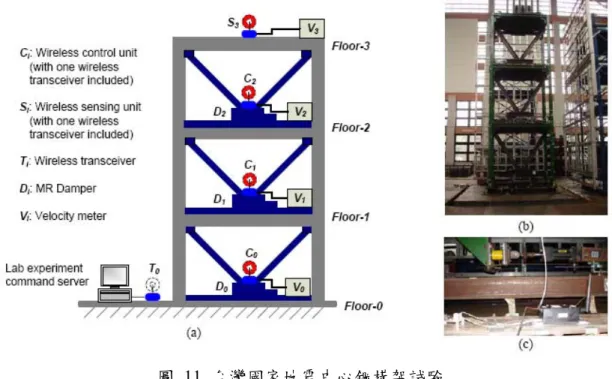
圖 11 台灣國家地震中心鋼構架試驗 ... 9
圖 12 無線感測系統感念圖 ... 9
圖 13 Kurata’s Wireless Sensor Test set-up: ... 10
圖 14 無線感測網路結構健康監測系統 ... 12 圖 15 無線感測網路結構健康監測系統功能圖 ... 12 圖 16 結構健康監測之感測模組規劃 ... 19 圖 17 無線感測平台硬體架構 ... 20 圖 18 感測模組功能方塊圖 ... 20 圖 19 本研究所發展之無線感測模組套件 ... 21 圖 20 無線感測平台主版與感測器連接圖 ... 21 圖 21 不同感測器置放位置示意圖 ... 22 圖 22 不同測試區域鋼材對 RSSI 的影響 ... 23 圖 23 平均 RSSI ... 23 圖 24 感測器置於封閉與開放空間示意圖 ... 23 圖 25 感測器置於封閉與開放空間對訊號 RSSI 的影響 ... 24 圖 26 感測器於鋼筋混凝土反力牆試驗位置示意圖 ... 24 圖 27 感測器置於反力牆內不同位置之 RSSI ... 25 圖 28 平均 RSSI ... 25 圖 29 建築物室內訊號測試平面圖 ... 26 圖 30RSSI 分佈圖 ... 26 圖 31 平均 RSSI ... 27 圖 32 不同量測時間之封包接收成功率比較. ... 27 圖 33 有時間排程與無時間排程對於封包接收成功率之比較 ... 28 圖 34 無線感測器所量得加速度 ... 28 圖 35 傳統有線感測器所量加速度 ... 29
圖 36 1HZ Sine Wave Input ... 29
圖 37 2.1HZ Sine Wave Input ... 30
表目錄 表 1 感測器的類型、量測類別與監測目的 ... 13 表 2 Displacement sensors ... 14 表 3 Velocity sensors. ... 14 表 4 Acceleration sensors. ... 15 表 5 Strain sensors. ... 15 表 6 Force sensors. ... 15 表7 Temperature sensors. ... 16 表 8 Pressure sensors. ... 16 表 9 Piezoelectric actuators. ... 16 表 10 速度計規格 ... 17 表 11 加速度計規格 ... 17 表 12 位移計規格 ... 18 表 13 應變計規格 ... 18
前言 長久以來,天然災害對人們的生命財產造成許多嚴重的傷害。因此在諸如地震、颱風 等災難發生前後,對結構物進行健康之診斷與評估更是目前重要的研究工作之一,尤其是 特定之重要公共建設或設施如醫院、消防局、災難處理中心、發電廠、水庫、主要橋梁道 路等。同樣的,如何在最短的時間內把主要倒塌或損壞結構的資訊傳送到災害應變中心, 以做最快速有效的災害搶救與資源分配也是相當重要的事。由於社會與政治之變遷快速, 使得目前的防災救災的工作勢單力薄,力量有限。而隨著人民知識與生活水準的日益提昇, 自我意識亦隨之提昇,政府應積極強化對人民生命財產安全的保護,以符合世界局勢與潮 流。因此,政府應儘速研訂具體有效的防災救災對策,積極結合產官學界之資源,以台灣 目前之科技優勢,研究發展下一代智慧型防災預防與警報系統,並有效加強與落實防災科 技研究成果於防災救災之預防工作,進而保障人民生命財產之安全。因此,整合先進科技 的『智慧型防災與預警系統』之研究與開發將是未來確保人民生命財產的重要課題。 本計畫為整合型計畫"智慧型無線感應器系統平臺建構與其在土木結構診斷應用之研 究"之子計畫,此整合計畫為以台灣目前在世界居於領先地位的先進資訊通訊技術 (Information and Communication Technology)為基礎,依據「地震與地震工程領域研究課
題 7:新材料、新工法與結構耐震性能之研究子項(2)發展先進智能材料成通訊技術在結構 安全即時監測與控制之應用」,擬開發建構『智慧型無線感應器系統平臺』並研究『其在土 木結構診斷應用』,計畫擬規劃實現內含五十個智慧型診斷點之土木結構監測與預警系統, 以整合土木、建築、通訊、控制與資訊等相關跨領域之技術,強化防災科技及其相關應用 之基礎研究,並加強防災科技落實於防災體系應用之研究,期能有系統地整合先進技術研 發智慧型防災與預警系統,以有效落實與推動防災救災之預防工作。 本整合計畫將透過技術開發與應用需求結合,以整合土木、通訊、電路設計、訊號處 理、自動控制與資訊軟體等相關跨領域之技術與專家,以建構專屬於土木結構診斷應用之 『智慧型無線感應器系統平臺』。希望藉由本計畫之執行與預期成效的獲得,能夠於未來強 化防災科技及其相關基礎研究與應用之研究,期能達到有效落實與推動智慧型防災與預警 系統之建立。
無線感測網路應用於土木結構健康監測可以看成一個完整的生命週期,如圖 1 所示。 經過有效的設計規劃進行感測器的佈置,進而建立一個完整的監測系統,監測系統將資訊 回授給後端做資料分析與損害評估,接著做出決策與判斷,最後將經驗也就是知識存進知 識庫中,提供給下一次監測系統設計與規劃的輔助資訊,構成一個完整的生命之期。此生 命週期的每一個環節都將提供其必要的資訊,使得智慧型監測系統可以自動修正與檢討而 達到最佳且完整的狀態。 Plane Design Decision Making Deployment Data Analysis and
Damage Estimating Monitoring Case Knowledge Storage Lifecycle of Wireless Sensor Network in Civil Engineering Infrastructure monitoring 圖 1 無線感測網路應用於土木工程監測之生命週期 然而,目前無線感測網路的研究中大多著重於感測器硬體的開發,實際上成功的應用 並不多,因為建置與應用無線感測網路於土木工程結構監測與傳統的監測系統相比雖有其 優點,但仍有相當多的問題,比如說實際土木工程環境、材料對無線訊號的影響、感測節 點佈置的位置、感測節點佈置的數量、佈置後的維護、資料的同步性等等。另外,不論無 線感測器硬體再怎麼成熟發展,沒有一個合適的應用領域也無法讓無線感測網路達到其應 有的效益。土木工程結構健康監測是一個可讓無線感測網路充分發揮的一個領域,然而土 木工程人員對於無線感測網路的知識缺乏、甚至是傳統監測的專家也無法快速的利用其建 立一個完整的監測系統。因為以無線感測網路為基礎的監測系統並非如傳統監測系統般的 單純,而需要許多跨領域的知識才能夠規劃與設計一個良好的無線感測網路監測系統。
研究目的 因此本子計畫的目的為無線感測平台之元件測試、環境干擾評估、網路健全度分析與 知識平台之開發,並應用於土木結構健康監測之規劃、設計與建置。整合土木工程結構健 康診斷的知識,並將原件測試、環境測試、網路測試等相關實驗所得到的資訊整合進去, 可以當作其他子計畫間良好的介面與橋樑。本子計畫為擬以三年的時間進行一系列之相關 研發工作主要為驗證與測試主計畫所發展之無線感測平台於土木建築環境的干擾評估、感 測器的性能評估,探討應用於結構健康監測的無線訊號同步問題,休眠與喚醒機制之研究, 感測節點存活的監控機制,測試其對於突發事件的處理能力,無線感測網路規劃與佈置之 建議等。最後並於實際大樓部署本總計畫所開發之無線感測器平台。 文獻探討 硬體
目前有相當多的研究致力於發展無線感測網路硬體,Dutta 等人(Dutta et al., 2005)設計 了一個新的無線感測平台可以進行有效的偵測、分群,並快速的回報資訊。並可以使用在
大尺度的範圍,可以長時間監測並且可以重複執行彈性的事件任務。圖 2 為其所發展的感
測器原型。
Werner 等人(Werner-Allen et al., 2005)發展了一個無線感測網路測試平台 MoteLab,這 個測試平台為以網際網路為基礎的平台,包含了感測節點、資料掘取中心、並提供了網路 的使用者介面,可以快速的部署感測節點,並包含了自動化的資料收集與除錯機制,其架
構如圖3 所示。
圖 3 MoteLab 架構圖
Park 發展了一個名為 Eco 的極小無線感測器(Park et al., 2005),體積只有 648mm3 重量
只有1.6g,一開始是設計用來監測幼兒的自發動作,但也可以用於其他領域。
圖 5 Eco compare to MICA2DOT
O'Flynn 發展了一個高度模組化與微小化的無線感測平台(O'Flynn et al., 2005),使用 2.4 GHz 的無線收發機,配有嵌入式軟體來達到省能的效果,由於其模組化的設計,其感測器
與制動器介面可以被無縫的整合,其大小為25mm 的立方塊,並且正在開發體積小於 10mm
立方塊的感測平台,圖為其所發展的無線感測平台。
圖 6 highly modular and miniaturized wireless platform for sensor networks 作業系統
目前國內外於無線感測網路作業系統的使用上,最為常用的為加州柏克萊大學所發展
的TinyOS 作業系統。TinyOS 其最早的 1.0 版本是由柏克萊大學於 2002 年 10 月份所發表
WindowsXP 等數種電腦作業平台,其優點為使用者可以藉由這個開放的作業系統,結合不
同的硬體來開發自己的相關應用。TinyOS 主要的設計目的為低電力與 ad-hoc 的感測網路。
其主要的元素為感測、驅動、網路通訊與電力管理。
圖 7 TinyOS Structure(TinyOS Overview, Crossbow Training document)
圖 8 無線感測技術之比較圖
http://doit.moea.gov.tw/news/newscontent.asp?IdxID=2&ListID=0613.
無線感測網路相關應用方面 近年來無線區域網路的發展使大家開始對感測器網路(Sensor Network)進行相關研究。 它是以感測為主要功能所發展出的網路架構模式,除了平時感測取得所需資訊外,並可依 照所收集的資料,進行儲存、運算及傳輸,並依此感測做出適當的回應動作(吳健豪, 尹華 強 et al. 2003)。無線感測網路的發展(王友群, 胡君琪 et al. 2003),最早是美國加州柏克萊 大學(UC Berkeley)的一項研究計畫,這項計畫開發出一種體積很小(與普通阿斯匹靈藥片大 小相似)的感測器如圖 9 所示,稱之為「智慧灰塵(Smart Dust)」(Arora, Dutta et al. 2004),採
用MEMS 技術。由於這項計畫是由美國國防部研究計畫單位(DARPA)所支助,原先的構想
是應用在軍事上。例如在戰場上,使用智慧灰塵技術來監控與了解敵軍的行蹤,如此一來, 就不需要冒著極大的危險派遣兵力深入敵方,便可完成蒐集敵軍情報的任務。
圖 9Wireless Sensor 智慧灰塵(Smart Dust)
而無線感測網路還有相當多的應用與研究(Akyildiz, Su et al. 2002; 王友群, 胡君琪 et al. 2003; 吳健豪, 尹華強 et al. 2003)。麻省理工學院的 LEACH(Low Energy Adaptive Clustering Hierarchy)計畫,改善原有的叢集網路(Cluster/Group Network),發展一個新的叢 集式網路,使其能讓感測器網路減少能源多餘的耗損,進而達到系統生命的延長。 SPIN(Sensor Protocols For Information Via Negotiation)計畫,是為了免除在網路上傳輸過多 不必要資料而損耗較多的能量,特徵在於各個感測節點須事先協商後才傳送資料,以免除 網路不必要的資料氾濫狀況,且各個感測節點可知道其現存能量的多寡,以對路由做適當 的調整,提高能量使用的效率。加州大學洛杉磯校區(UCLA)在無線網路的部份,改善在低
功率鏈結層的通訊協定,以及硬體上可重新設定的節點、以低功率 I/O 為中心的無線多媒 體節點。在低功率與能量探知系統方面,主要為因應低功率消耗網路系統,以乾電池為電 力來源,為了達到持續幾個月不需更換電池,則平衡運算與傳輸之間所耗能量的比例是其 研究重點。
無線感測網路於結構健康監測與損害評估方面
Farrar 提出現在大部分的結構健康監測系統(Farrar et al., 2006b),都是工程師利用現有 已發展好的系統,嘗試去驗證可由此系統所量得的特定的損害,在大多情況,都是沒有效 率的,因此研究學者們開始發展適合結構健康監測的感測網路系統。作者並提出設計一個
好的結構健康監測系統必須注意1.要被攫取的資料類型 2.感測器的類型、數量和位置 3.頻
寬、靈敏度、動態範圍4.資料擷取、通訊和儲存的系統 5.電源的需求 6. 試驗取樣的間隔(包
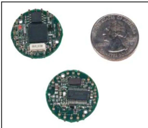
含連續監測、事件觸發、或是定期取樣)7.處理器和記憶體的需求和外力激發的來源(主動 式)。Wang 等人(Wang et al., 2005)提出一個整合的無線監測系統,可以支援多無線感測點之
即時的資料擷取。圖10 為其利用小型鋼構架來測試其系統。其並於南韓的 Geumdang Bridge
橋佈設其無線感測系統。
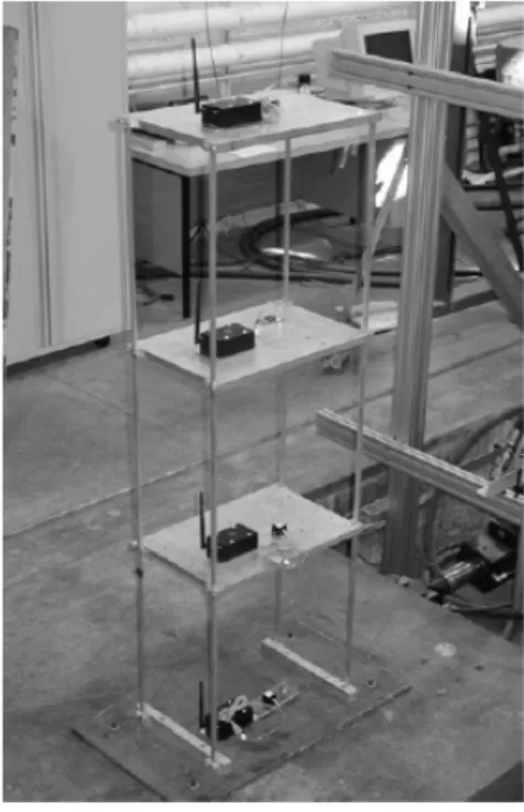
Wang 等人提出了分散式的結構控制(Wang et al., 2006),並將控制的演算法嵌入無線感
測平台,並於三層樓的半尺度鋼架,每層樓並配置一個MR damper 的模型來測試。
圖 11 台灣國家地震中心鋼構架試驗
在國外有許多應用無線感測網路於結構監測方面的相關研究(Jerome Peter Lynch 2002; Mehta and El Zarki 2004; Olariu, Wada et al. 2004),Lynch 等提到無線感測的監測技術除了可 以降低成本(Jerome Peter Lynch 2002),並且可以使監測系統更加的彈性化,圖 12 為無線感 測模組的概念圖。
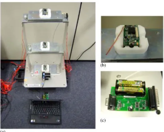
Xu 等人(Xu, Rangwala et al.)設計了一個名為 Wisden 的無線感測網路系統用來收集結構 的狀態資料,並且利用以小波為基礎的壓縮方法來克服低電源無線感測訊號頻寬限制的問 題。Kurata 與 Spencer 等人(Kurata, Jr. et al.)以 Berkeley Mote platform 為平台應用於建築物
之風險監測,並以兩層樓之鋼架來測試其效能,在其實驗中測試了加速度感測器與Berkeley
Mote platform 無線傳輸之效能,圖 13 為其實驗架構與使用之感測器模組。在感測器之開發 上,Lynch 等人(Lynch, Partridge et al.)設計了一個高效能平面壓阻式之加速度微感應器,利 用此壓阻式微感應器可用來設計一低成本之無線感測單元,自動監測結構物之加速度,其 並以一個五層樓之構架來測試此加速度器應用於無線感測系統之效能。
圖 13 Kurata’s Wireless Sensor Test set-up:
(a) Test structure A; (b) MICA; and; (c) Base station. (Kurata, Jr. et al.)
國內在無線感測網路相關研究方面,鄭山川“提出了 tatic PEAS-AP"和“dynamic
PEAS-AP"兩個方法去調整感測器探測範圍並且有效地延長感測網路生命期到最大。其在
最後模擬中顯示,使用static PEAS-AP 和 dynamic PEAS-AP 的感測網路生命期會比在 PEAS
中盲目的選擇探測範圍的感測網路生命期好得多。胡偉德描述了一種繞送機制並能偵測無 線感測器網路上之故障非靜止的錯誤。這個機制主要為以建立節點不相交的路徑及使用投
票方法來找出故障的感測器。這個機制成功地實作在NS2 網路模擬器(NS2 simulator),實 驗結果顯示這個機制僅需些許的負擔便可以有效地檢測故障的感測元件。 研究方法 本研究利用商用之無線感測平台於土木結構診斷應用之相關元件、材料、環境等測試 來規劃與提供總計畫所發展之無線感測平台之相關參數與建議。第一年主要的工作為以熟 悉感測網路相關技術,規劃並選擇適合土木結構診斷之無線感測網路技術為主要工作,第 二年本研究將以第一年之成果來輔助總計畫之無線感測平台開發,並針對總計畫所發展之 10 套無線感測系統模組原型(Prototype)於土木結構診斷應用之功能測試與驗證,主要分 為(1) 驗證與測試主計畫所發展之感測器的性能評估(2)驗證與測試主計畫所發展之無線感 測平台於土木建築環境的干擾評估(3)探討應用於結構健康監測的無線訊號同步問題 (4)探 討適用於土木結構健康監測的路由協定與無線感測網路之覆蓋問題。利用現在國際上常用 的商用無線感測系統,針對相關元件作一系列之測試,包含元件測試、環境對無線感測器 之干擾測試、土木建築材料對無線感測器的干擾測試、探討與研究適合土木結構診斷之無 線感測系統,並計畫利用小型模擬地震震動台配合所設計之小型構架來驗證與測試相關元 件之效能與其穩定性,並可與傳統感測單元相互比較。此資訊將可回饋給子計畫一至三作 為開發感測平台之參考。 研究結果與討論 即時無線感網路之結構健康監測系統 本研究的無線感測平台架構包含了感測器、資料擷取模組、無線傳輸與控制模組,基 地台與個人電腦。本無線感測系統處理程序與流程為當感測器偵測到訊號時會將訊號傳送 給資料擷取模組,資料擷取模組接收到訊號後再傳送給無線傳輸與控制模組來處理,並藉 由無線傳輸將訊號傳送至接收端之無線傳輸與控制模組,並由與個人電腦連接之基地台將 資料傳送至個人電腦做後續之資料處理與分析。感測器模組主要為包含了兩個感測元件, 一個為高精度的三軸加速度晶片,另一個為量測微振用的單軸加速度晶片。此感測模組也 包含了兩個24bit 的高精度 AD 分別與兩個加速度晶片連接,利用程式可以切換至任一個感 測晶片來做為量測之用。圖14 為本研究所發展的監測系統介面,圖 15 為其主要功能圖。
系統主要分為四個部分,第一個部分是資歷呈現的部分,可以在 PC 上即時顯示資料的波 形,或是利用網頁的方式呈現。第二個部分為感測節點的拓樸節點健康狀況的監測。第三 個部分為訊號處理與分析,第四個部分為結構健康監測的部分,可以找出破壞的位置與程 度並給出警告。 圖 14 無線感測網路結構健康監測系統 WSN‐ASHMS System Functions Data Representation Viewer Signal Processing and Analysis Structural Health Monitoring and Warning Sensor Nodes Topology Viewer and Health Monitoring Data Base PC BasedData Representation Web BasedData Representation Node Topology View Battery Monitoring Nodes Life Inspection FFT Wavelet Filter FRF Damage Detecting Damage Location Damage Level Warning 圖 15 無線感測網路結構健康監測系統功能圖
無線感測網路平台感測節點規劃 本研究將依結構健康監測的需求來規畫出適合之專屬無線感測模組。一般土木結構監 測系統主要量測結構的應力、應變、位移與量測環境的溫度、濕度等等。而量測的感測器 常用的有加速度計、速度計、應變計、荷重計、沉陷計、變位計、表面型溫度計、熱藕計、 相對溼度計等。茲將常用到的感測器分類整理如下。 表 1 感測器的類型、量測類別與監測目的 感測器類型 量測類別 監測目的 加速度計 結構的狀態 1. 竣工後橋梁結構地震反應資料即時記錄 2. 地震地表輸入資料蒐集 3. 橋梁基本振動頻率量測,可瞭解橋梁動態 特性,並與理論分析值比對。 4.結構系統識別。 速度計 結構之微震量測 位移計 量測橋梁與結構之位移變化 應變計 量測混凝土與鋼結構之應變 相對濕度計 量測環境之濕度變化 溫度計 量測環境之溫度變化 另外,感測器其試驗目的、荷載性質、試驗對象、試驗場合、結構破壞與否等不同因 素而有所不同,分類如表2-9。
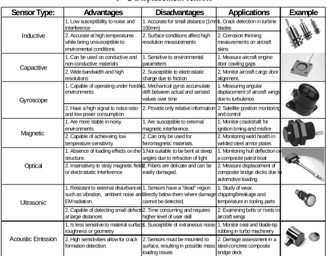
表 2 Displacement sensors
Sensor Type: Advantages Disadvantages Applications Example
1. Low susceptibility to noise and interference
1. Accurate for small distance (1mm-150mm)
1. Crack detection in turbine blades
2. Accurate at high temperatures while being unsusceptible to enviromental conditions
2. Surface conditions affect high resolution measurements
2. Corrosion thinning measurements on aircraft skins
1. Can be used on conductive and non-conductive materials
1. Sensitive to environmental parameters
1. Measure aircraft engine door cowling gaps 2. Wide bandwidth and high
resolutions
2. Susceptible to electrostatic charge due to friction
2. Monitor aircraft cargo door alignment.
1. Capable of operating under hostile environments
1. Mechanical gyros accumulate drift between actual and sensed values over time
1. Measuring angular displacement of aircraft wings due to turbulence.
2. Have a high signal to noise ratio and low power consumption
2. Provide only relative information 2. Satellite position monitoring and control
1. Are more stable in noisy environments
1. Are susceptible to external magnetic interference.
1. Monitor crackshaft for ignition timing and misfire 2. Capable of achieveing low
temperature sensitivity.
2. Can only be used for ferromagnetic materials.
2. Monitoring weld health in welded steel armor plates 1. Absence of loading effects on the
structure.
1.Not suitable to be bent at steep angles due to refraction of light
1. Monitoring hull deflection on a composite patrol boat 2. Insensitivity to stray magnetic fields
or electrostatic interference
2. Fibers are delicate and can be easily damaged.
2. Measure displacement of composite bridge decks due to automotive loading. 1. Resistant to external disturbances
such as vibration, ambient noise and EM radiation.
1. Sensors have a "dead" region directly below them where damage cannot be detected.
1. Study of wear, chipping/breakage and temperature in tooling parts 2. Capable of detecting small defects
at large distances
2. Time consuming and requires higher level of user skill
2. Examining bolts or rivets in aircraft wings
1. Is less sensitive to material surface roughness or geometry
1. Susceptible ot extraneous noise 1. Monitor seal and blade-tip rubbing in turbo machinery 2. High sensitivities allow for crack
formation detection.
2. Sensors must be mounted to surface, resulting in possible mass loading issues 2. Damage assessment in a steel-concrete composite bridge deck Capacitive Gyroscope Magnetic Optical Ultrasonic Acoustic Emission Inductive 表 3 Velocity sensors.
Sensor Type: Advantages Disadvantages Applications Example
1. High sensitivity and excellent noise immunity
1. Susceptible to electromagnetic field interference
1. Measuring gear speed in an automotive gearbox 2. Lower output, for use in high speed
applications
2. Must be mounted perpendicular to plane of motion
2. Measure rotational speeds in gas turbine engines 1. High accuracy and high reliability 1. Difficult to measure parts in hard
to reach areas
1. Monitoring vibrations of automotive tires 2. Not affected by surface roughness
or color
2. Requires powered light source 2. Monitor molten plastic flow in injection molding process 1. Larger frequency range then
magnetic sensors
1. Response is nonlinear for low frequencies (<10Hz)
1. Measure vibrations in cavitating pumps. 2. Reduces signal noise for high
frequency measurements.
2. Requires sensor to be mounted to structure.
2. Monitor seals in paper handling machines.
Piezoelectric Magnetic Induction
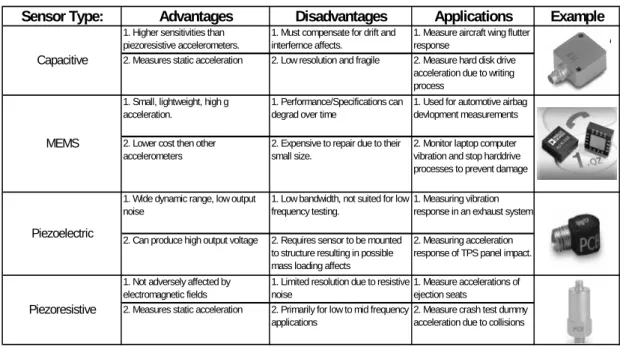
表 4 Acceleration sensors.
Sensor Type: Advantages Disadvantages Applications Example 1. Higher sensitivities than
piezoresistive accelerometers.
1. Must compensate for drift and interfernce affects.
1. Measure aircraft wing flutter response
2. Measures static acceleration 2. Low resolution and fragile 2. Measure hard disk drive acceleration due to writing process
1. Small, lightweight, high g acceleration.
1. Performance/Specifications can degrad over time
1. Used for automotive airbag devlopment measurements 2. Lower cost then other
accelerometers
2. Expensive to repair due to their small size.
2. Monitor laptop computer vibration and stop harddrive processes to prevent damage 1. Wide dynamic range, low output
noise
1. Low bandwidth, not suited for low frequency testing.
1. Measuring vibration response in an exhaust system 2. Can produce high output voltage 2. Requires sensor to be mounted
to structure resulting in possible mass loading affects
2. Measuring acceleration response of TPS panel impact. 1. Not adversely affected by
electromagnetic fields
1. Limited resolution due to resistive noise
1. Measure accelerations of ejection seats
2. Measures static acceleration 2. Primarily for low to mid frequency applications
2. Measure crash test dummy acceleration due to collisions
Piezoelectric
Piezoresistive Capacitive
MEMS
表 5 Strain sensors.
Sensor Type: Advantages Disadvantages Applications Example 1. Capable of recognizing static
forces
1. Requires sensor to be mounted to structure
1. Measure strains in gas turbine fan blades 2. Simplicity of mounting to the
surface
2. Susceptible to external sources of noise and temperature
2. Measure helicopter blade deflections
1. Not susceptible to electromagnetic interference
1. Requires fiber optic cable to be run to each sensor
1. Strain monitoring of civil structures, for instance bridges, dams, buildings, pipelines .
2. Multiplexing capability 2. Requires a power source 2. Monitoring ship hul strains
Piezoresistive
Optical
表 6 Force sensors.
Sensor Type: Advantages Disadvantages Applications Example 1. High stiffness allows direct
insertion in machine structures
1. More expensive then other types 1. Recording impact forces in military applications 2. High natural frequencies, ideal for
quick transient forces
2. The output can be nonlinear 2. Measuring wave forces on off-shore oil platforms 1.Multiplexing capability 1. Requires fiber optic cable to be
run to each sensor
1. Monitoring traffic loads over the span of a bridge 2. Ideal for high temperature
applications
2. Requires a power source 2. Measure clamping force of a car window closing
Optical Piezoresistive
表 7 Temperature sensors.
Sensor Type: Advantages Disadvantages Applications Example 1. Capable of operating in cryogenic
temperature range
1. Susceptible to external sources of noise
1. Measuring temperature inside catalytic converters
2. Immune to high levels of radiation 2. Sensors must be mounted to surface
2. Temperature measurement for feedback control of engine combustion
1. Negligible electromagnetic interference affects.
1. fiber optic cables are delicate and limit maximum temperature
1. Measuring temperature of electric generators 2. Small and flexible for easy
installation
2. Slow data processing 2. Temperature monitoring in semi-conductor manufacturing 1. Typically cheaper than other
sensors
1. Resistance vs. temperature is nonlinear causing limited temperature range
1. Measure automotive engine oil and coolant temperatures 2. Easy implementation due to small
size
2. Limited operating temperature range
2. Measure inside air temperature in HVAC systems 1. Offer higher temperature range
then thermoresistive sensors
1. Have upper temperature limit of 3100F
1. Engine and turbine exhaust gas monitoring
2. Are cheapest of all temperature sensors
2. Measured temperatures drift over time
2. Heat treating and metals processing temperatures Thermoelectric Thermoresistive Acoustic Optical 表 8 Pressure sensors.
Sensor Type: Advantages Disadvantages Applications Example
1. Measure both static and dynamic pressures
1. Increase in pressure might lead to transducer becoming nonlinear
1. Measure engine combustion chamber pressures
2. Reliable under varying environmental conditions
2. Can produce significant electrical noise.
2. Measure jet engine pressure at inlet and outlet of each component
Piezoresistive
表 9 Piezoelectric actuators.
Configuration: Sensing Direction: Advantages: Disadvantages: Applications:
Transverse
1. Ideal for static and low frequency applications. 2. Capable of applying tension and compression loads
1. Low electro-mechanical coupling 2. Requires strong bonds to ensure high fidelity. 3. Stability problems for large displacement
1. Fine tuning of laser equipment. 2. Alignment of fiber optics. 3. Control injection valves in the automotive industry
Shear
1. Extremely reliable (>109 cycles). 2. High resonant frequencies.
1. Needs to be pre-loaded to avoid un-poling resulting in lowered operational frequencies.
1. Atomic force microscopy. 2. Active vibration cancellation.
Tube Transverse
1. Capable of measuring displacements along all three axes. 2. Sub-nanometer resolution
1. Small Displacement 2. Relative to stack actuators, small force
1. Hard drive read/write head testing. 2. Needle valve actuation.
Ring Transverse
1. Available with clear aperatures for transmitted-light applications. 2. High resolution for static/dynamic applications.
1. More delicate than other configurations due to the center bore 2. Low force
1. Image positioning. 2. Micropositioning
Disk Transverse
1. Provide a relatively large travel range for their size. 2. Fast response w/ sub-nanometer resolution
1. Low force
1. Knife edge control in extrusion tools. 2. Tuning of circular boring, drilling processes.
Bimorph (PVDF) Transverse/Shear
1. Low operating voltage. 2. Excellent resistance to humidity.
1. Low frequency operation. 2. Low resolution (unsuitable for precision). 3. Low force and slow response
1. Position control of pneumatic valves. 2. Measuring accelerations of flexible structures. Stack
本研究為開發適用於結構健康監測之無線感測平台,由於應用於結構健康監測之監測 項目與感測器種類繁多,因此,本研究主要針對結構監測常用之加速度計、應變計等常用 之規格來設計。 以量測結構的動態參數來說,結構動態參數包含自振頻率、阻尼比、振型等參數,這 些參數基本上跟結構的負載無關,跟結構的形式、勁度、質量分佈,材料特性有關。常用 的結構動態參數方法有自由振動法、共振法、微振量測法。自由振動法是利用使結產生自 由振動,利用感測系統將結構之自由衰減震動曲線紀錄下來,藉此求出結構的動力特性參 數。共振法則是利用激盪器連續改變頻率,當結構出現共振時,此時的頻率即為結構之自 振頻率。微震量測法是利用結構周圍微小的震動來決定結構的基本動力特性。微震量測法 對儀器的要求比較高,由於目前結構物越來越高,橋梁跨距越來越長,自振頻率相對的低, 長江三峽萬縣鋼筋混凝土拱橋:豎向震動頻率 0.39Hz,橫向震動頻率 0.2Hz,香港青馬大橋自 振頻率為0.06Hz,因此要求感測器與放大器的頻率下限要夠低。再來由於微震量測是採用 自然環境的激勵,振動信號微弱,因此要求感測器要有足夠之靈敏度。靈敏度的計算為最 大輸出電壓除以感測器的量測範圍,以一般5V 輸出的感測器來說,若感測範圍為 1g,則 其靈敏度為5 V/g。另外在結構的強迫振動反應試驗與微震量測相比,由於外加荷載造成結 構的反應要微震大,結構動力反應測試的感測器規格要求就相對的比較低一點。表 10-13 為本研究整理之常用感測器之規格。 表 10 速度計規格
Sensor Type Function 頻率範圍 (Bandwidth)
Sensitivity Resolution Max. output voltage
Power supply Commercial Product 速度計 微震量測 0.2~100Hz 1V/kine(c m/s)或 10V/kine 15×10-7m/s (Appro.1 50μkine) 10V DC±15V VSE-15D 表 11 加速度計規格
Sensor Type Function 頻率範圍 Sensitivity Resolution Max. output
(Bandwidth) voltage Product 加速度計 地震加速 度量測 0.2-200HZ 1-2V/g 2*10-3-2* 10-5g 3-5V 3-5V CXL01LF1 表 12 位移計規格 Sensor Type 功能 解析度 輸入電壓 最大輸出電壓 常用廠牌 LVDT 位移計 2.5mV 2-5V 5V SDP-CT 表 13 應變計規格 Sensor Type 功能 解析度 輸入電壓 最大輸出電壓 常用廠牌 STRAIN GAGE 量測應變 Gage Factor= 2.1 5V(電阻 120 歐姆) -16V(350 歐姆) 5-16V VISHAY, KYOWA 由上述選擇感測器的條件與感測器的相關參數,本研究將感測模組分為四種,分別為 1.Vibration Type; 2.Strain Type; 3.Environment Type; 4.General Type。Vibration Type 主要以量 測加速度之加速度計為主。Strain Type 為量測應變,內建惠斯頓電橋電路使應變計達到隨 插即用之功能。Environment Type 主要是量測結構之環境參數包括溫度、濕度等等。因為感 測器的種類實在太多,因此,General Type 的目的為讓使用者依其感測需求可以外接不同的 感測元件來達成所需之應用。此架構可以很容易架構出所需之無線感測網路,將無線傳輸 模組與不同的感測模組可以搭配出不同的感測結點,而未包含感測功能的無線傳輸模組可 以當做中繼站、或是與PC 結合成為接收端。另外在 AD 的選擇上,本研究提出下述公式推 導配合感測器相關規格來選擇出我們所需的ADC。
Resolution min = ( device range/2resolution ) × ( 1/Sensitivity )
以加速度計為例,假設Resolution min 為我們所需要測量出的加速度最小解析度,單
位為(G)。device range 為 ADC 能夠輸入的最大電位差,而 2 的 resolution 次方則依不同的 ADC 有不同的數值,通常為 12 (bits)或者是 16(bits),最後 Sensitivity 為加速度計的敏感度,
Resolution,當因諸如經費考量等因素不能使用較大敏感度的加速度計,則可以選擇 Resolution 較高的 ADC,例如使用 16bits ADC 取代 12 bits ADC,來達到我們的需求。
2008/12/18
Dept. of Civil Engineering, NCTU 16
Structural Health Monitoring Based Wireless Sensor Networks Platform Wireless Communication and Processing Module Sensor Module • Vibration Type • Strain Type • Environment Type • General Type
Vibration
Node
Strain Node
Environment
Node
Accelerometer Strain gage Thermometer
Humidity
Sensor
interface
Node
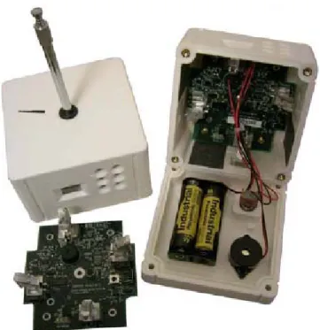
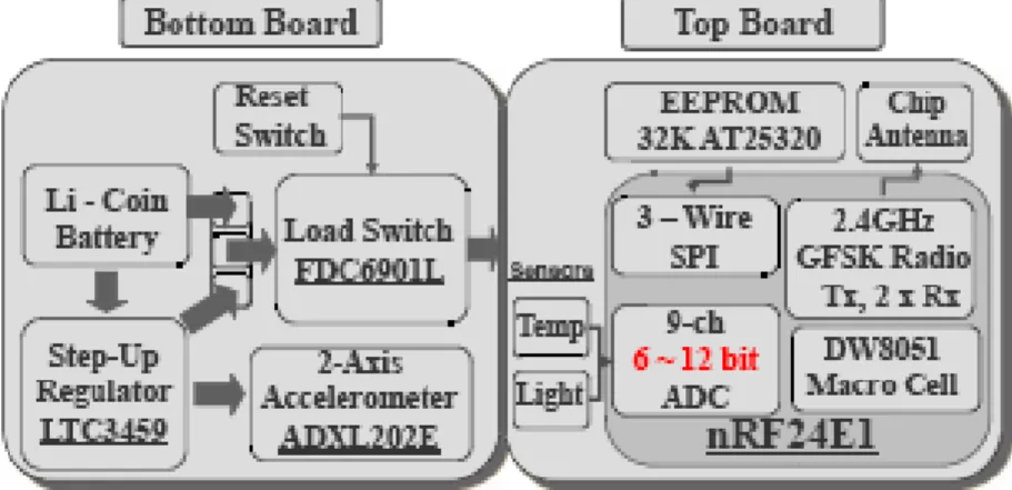
Specific senor Wireless module +Sensor module=Wireless Sensor Node 圖 16 結構健康監測之感測模組規劃 總計畫所發展的無線感測平台硬體 本計畫為驗證總計畫所發展的無線感測平台,平台的硬體架構如圖17 所示。本硬體平 台主要分為三個部分,分別為無線感測節點主板、感測模組和程式燒錄除錯版。本計畫所 設計之無線感測節點主板是以CC2430/31 EMK Module 為核心,採用 TI 所設計之 CC2430RF Chip 作為無線通訊模組。CC2430 是一個可嵌入式、採用表面黏著技術(Surface Mount Technology)、並遵照 IEEE802.15.4 規格的無線模組,具有一個 8-bit 8051 的微處理器與一
個2.4GHz IEEE802.15.4 規格的無線射頻收發器,並可工作在該頻段的 16 個不同的頻道。
除了標準的IEEE 無線射頻與 PHY/ MAC 無線介面。在主板之硬體設計,我們規劃了各種
工業標準之介面,如類比數位轉換、序列傳輸介面(SPI Socket)、RS232 介面(USART Socket)
Sensor Board with SPI Interface RS232 connecter board JTAG‐usb connecter board Adaptive Wireless Sensor Platform Hardware system CC2430/31 Module Connector Power Unit JTAG Socket USART Socket SPI Socket A/D Socket Battery Container Sensor Board with Analog output WSN Node Main Board Functionality Block Sensor Module Debugging Module 圖 17 無線感測平台硬體架構 感測模組功能方塊圖如圖18 所示,感測模組參考前述之規畫,主要分兩種型式,Type1 的感測模組為數位式,直接與主板上的SPI 介面溝通,或是感測器直接與主板上的 AD 來
溝通,Type2 為感測模組有一個 24bit 的 AD,感測器的資料由這顆 AD 來擷取,利用 SPI
介面與主版來溝通。圖19 為本研究所發展的無線感測平台套件,圖 20 為其與主板與感模 組連接的示意照片。
Sensor
Module
Circuit
SPI
Connector
A/D
Connector
Sensor Module
Circuit
SPI
Connector
24Bits
A/D
WSN Sensor Module
WSN Sensor Module: Type1
WSN Sensor Module: Type2
圖 18 感測模組功能方塊圖圖 19 本研究所發展之無線感測模組套件 圖 20 無線感測平台主版與感測器連接圖 無線感測器於土木工程環境與材料之干擾測試 本研究對無線感測器無線訊號的傳輸環境對於接收訊號強度是相當重要的。遮蔽效應 (Shadowing Effect)是由於無線訊號發射端與接收端之間的電波傳播受到物體阻隔,使得電 波傳播損耗增大的現象。當發射端與接收端處在不同的環境中,遮蔽效應所造成的傳播損 耗亦有所不同;因此遮蔽效應亦會影響到訊號的涵蓋區域大小,與可監測接收距離的長短。 由於無線感測器會置於土木建築結構上或是埋入結構內部,遮蔽效應相當大,因此需要了
解當感測器置於結構上或是結構內是否有有效的傳輸,傳輸距離是否會受影響,因此本研 設計一系列的實驗,來測試無線感測器的傳輸效能。
由於鋼材為土木結構最常用的材料,金屬對無線訊號的影響也很大,因此本研究將無
線感測結點至於鋼樑不同位置來評估其對訊號的影響。由圖22 可知在遮蔽比較大的位置,
對無線訊號的RSSI 比較低(越高越好),其影響也可由圖 22 看出。在開放空間(Free),其 RSSI
的值較穩定,有鋼材影響時,訊號跳動較大。圖23 為其平均 RSSI 的值,由圖也可以看出 開放空間的RSSI 值較高(越高訊號越好)。 對於封閉性越高的遮蔽其影響越大也可以由圖25 可以看出。為了測試鋼筋混凝土對於 無線訊號的影響,本研究利用交通大學結構實驗室之鋼筋混凝土反力牆來做測試,由圖27 可知一二樓間的鋼筋混凝土樓板對訊號的影響最大,可以看出其訊號不穩定,跳動最大, 平均RSSI 也最差,反力牆的通道因為是貫通的,所以訊號最為穩定。
Sending node
Receiving
node
6m
A
B
圖 21 不同感測器置放位置示意圖‐80 ‐75 ‐70 ‐65 ‐60 ‐55 ‐50 ‐45 ‐40 0 5 10 15 20 25 30 RS SI Number of Node Place A Place B Rree 圖 22 不同測試區域鋼材對 RSSI 的影響 ‐66 ‐64 ‐62 ‐60 ‐58 ‐56 ‐54 ‐52 B A Free 數列1 ‐65.48275862 ‐57.24137931 ‐56.72413793 R SSI 圖 23 平均 RSSI
Open Space
High
isolated
圖 24 感測器置於封閉與開放空間示意圖‐80 ‐75 ‐70 ‐65 ‐60 ‐55 ‐50 ‐45 ‐40 0 5 10 15 20 25 30 RS S I Number of Node Rree 封閉空間 圖 25 感測器置於封閉與開放空間對訊號 RSSI 的影響
Mid
1m
2
ndFloor
1
stFloor
A thickness of 50 in 50cm floorTop View
Side View
Transmitter
Receiver
圖 26 感測器於鋼筋混凝土反力牆試驗位置示意圖‐100 ‐90 ‐80 ‐70 ‐60 ‐50 ‐40 0 5 10 15 20 25 30 R SSI Number of Node 反力牆Tunnel Mid 2 Floor 圖 27 感測器置於反力牆內不同位置之 RSSI ‐90 ‐80 ‐70 ‐60 ‐50 ‐40 ‐30 ‐20 ‐10 0
反力牆 Tunel Mid 2floor
數列1 ‐80.27586207 ‐62.06896552 ‐74.86206897 R SSI 圖 28 平均 RSSI 本研究也在建築物室內擺放節點測試訊號的穩定度,節點佈置平面圖如圖29 所示,其 中B 點為接收節點,圖其 60 秒測試時間的 RSSI 分佈圖。由圖中可以很明顯的看出 Node4
距離B 點最近,其 RSSI 的訊號最好 Node1 置於房間其訊號跳動大,Node5 置於樓梯間,
因此訊號最差,且跳動最大最不穩定。圖31 為其平均 RSSI,由圖中也可以看 node4 的訊
B 1 2 3 4 5 圖 29 建築物室內訊號測試平面圖 ‐100 ‐90 ‐80 ‐70 ‐60 ‐50 ‐40 0 10 20 30 40 50 60 70 RS SI Number of Node Node1 Node2 Node3 Node4 Node5 圖 30RSSI 分佈圖
圖 31 平均 RSSI 感測網路時間排程試驗 對於長時間的量測,封包接收成功率必須被考慮。圖32 比較了封包接收成功率對於不 同量測時間的比較。如圖所示,封包接收成功率會隨著時間的增加而下降。圖33 顯示了良 好時間排程的重要性,如圖,如果有良好時間排程,封包接收成功率幾乎百分之百,此外, 在只有兩個節點同時送封包到接收端時,封包接收成功率可以到達百分之九十,然而,當 超過三個節點時,封包接收成功率會大幅的下降。 0.9925 0.993 0.9935 0.994 0.9945 0.995 0.9955 0.996 0.9965 0.997
10min 30min 60min 120min
Success Packets Received Rate
0 0.1 0.2 0.3 0.4 0.5 0.6 0.7 0.8 0.9 1 Well Time Schedule Non Time Schedule (2 nodes to Base) Non Time Schedule (3 nodes to Base) 圖 33 有時間排程與無時間排程對於封包接收成功率之比較 感測器校正 本研究將所發展之無線感測器置於振動台測試,與傳統有線加速度計比較,圖34 為無 線感測器,圖35 為有線感測器,由圖中可以看出不論是波形與振幅都相當的一致。另外, 本研究利用振動台輸入不同頻率的正弦訊號,由圖36 到 38 可以清楚的看出,本研究發展 之感測器可以準確的量所要的頻率的訊號。 0 5 10 15 20 25 -0.3 -0.2 -0.1 0.0 0.1 0.2 0.3 0.4 g Time(Sec) 圖 34 無線感測器所量得加速度
0 5 10 15 20 25 -0.3 -0.2 -0.1 0.0 0.1 0.2 0.3 0.4 g Time(Sec) 圖 35 傳統有線感測器所量加速度 0.0 0.5 1.0 1.5 2.0 0.000 0.005 0.010 0.015 0.020
Frequency
Amplitude
-15000 -10000 -5000 0.0 0.2 0.4 0.6 0.8Frequency
1.0 1.2 1.4 1.6 1.8 2.0Ph
a
s
e
1.6 1.8 2.0 2.2 2.4 2.6 2.8 3.0 0.00 0.02 0.04 0.06 0.08
Frequency
Amplitude
4000 6000 8000 10000 12000 1.5 2.0Frequency
2.5 3.0Phase
圖 37 2.1HZ Sine Wave Input
2.0 2.5 3.0 3.5 4.0 0.00 0.05 0.10 0.15
Frequency
A
m
plitude
-6000 -4000 -2000 2Frequency
3 4Phase
結論 本子計畫的目的為無線感測平台之元件測試、環境干擾評估、網路健全度分析與知識 平台之開發,並應用於土木結構健康監測之規劃、設計與建置。整合土木工程結構健康診 斷的知識,並將原件測試、環境測試、網路測試等相關實驗所得到的資訊整合進去,可以 當作其他子計畫間良好的介面與橋樑。第一年主要的工作為以熟悉感測網路相關技術,規 劃並選擇適合土木結構診斷之無線感測網路技術為主要工作本研究第二年針對總計畫所開 發之無線感測器進行測試,無線訊號的傳輸環境對於接收訊號強度是相當重要的。遮蔽效 應(Shadowing Effect)是由於無線訊號發射端與接收端之間的電波傳播受到物體阻隔,使得 電波傳播損耗增大的現象。當發射端與接收端處在不同的環境中,遮蔽效應所造成的傳播 損耗亦有所不同;因此遮蔽效應亦會影響到訊號的涵蓋區域大小,與可監測接收距離的長 短。由於無線感測器會置於土木建築結構上或是埋入結構內部,遮蔽效應相當大,因此需 要了解當感測器置於結構上或是結構內是否有有效的傳輸,傳輸距離是否會受影響,因此 本研設計一系列的實驗,來測試無線感測器的傳輸效能。本研究分別測試了無線感測器於 土木工程環境與材料之干擾測試,感測網路時間排程試驗,並發展了無線結構健康監測系 統之使用者介面,提供總計畫使用。
參考文獻
1. O. Gassmann, H.M., ed. Sensors Applications. Sensors in Intelligent Buildings, ed. J.W.G. J. Hesse, W. Gopel. Vol. 2. 2000, Wiley-VCH Verlag GmbH.
2. Mufti, A.A., B. Bakht, and G. Tadros. SHM technologies for civil engineering intelligent infrastructure. in Proceedinigs of The Second International Conference on Structural Health Monitoring of Intelligent Infrastructure. 2005. Shenzhen,China: Taylor & Francis.
3. Kiremidjian, A.S., et al. Structural Damage Monitoring for Civil Structures. 4. 吳健豪, 尹華強, and 許獻聰, 感測網路的技術與進展. 通訊雜誌, 2003(116).
5. 王友群, 胡君琪, and 曾煜棋, 感測網路將走入人類日常生活. 通訊雜誌, 2003(116). 6. Arora, A., et al., A line in the sand: a wireless sensor network for target detection,
classification, and tracking. Computer Networks-the International Journal of Computer and Telecommunications Networking, 2004. 46(5): p. 605-634.
7. Hellerstein, J.M., W. Hong, and S.R. Madden, The sensor spectrum: Technology, trends, and requirements. Sigmod Record, 2003. 32(4): p. 22-27.
8. Havinga, P., J.C. Hou, and F. Zhao, Wireless sensor networks. Ieee Wireless Communications, 2004. 11(6): p. 4-5.
9. Marsh, D., et al., Autonomic wireless sensor networks. Engineering Applications of Artificial Intelligence, 2004. 17(7): p. 741-748.
10. Wadaa, A., et al., Training a wireless sensor network. Mobile Networks & Applications, 2005. 10(1-2): p. 151-168.
11. Oyman, E.I. and C. Ersoy, Overhead energy considerations for efficient routing in wireless sensor networks. Computer Networks-the International Journal of Computer and Telecommunications Networking, 2004. 46(4): p. 465-478.
12. Olariu, S., et al., Wireless sensor networks: Leveraging the virtual infrastructure. Ieee Network, 2004. 18(4): p. 51-56.
13. 丁志明等, 微機電系統技術與應用. 伍秀菁、汪若文、林美吟 ed. 2003: 行政院國家科 學委員會精密儀器發展中心.
14. Vijay K. Varadan, K.J.V.a.K.A.J., RF MEMS and Their Application. 2003: John Wiley & Sons.
15. Thepvilojanapong, N., Y. Tobe, and K. Sezaki, SDC: A scalable approach to collect data in wireless sensor networks. Ieice Transactions on Communications, 2005. E88B(3): p. 890-902.
16. Luo, H.Y., et al., TTDD: Two-tier data dissemination in large-scale wireless sensor networks. Wireless Networks, 2005. 11(1-2): p. 161-175.
17. Zhao, J.L., et al., Optimizing sensor node distribution with genetic algorithm in wireless sensor network. Advances in Neural Networks - Isnn 2004, Pt 2, 2004. 3174: p. 242-247. 18. Mehta, V. and M. El Zarki, A bluetooth based sensor network for civil infrastructure health
monitoring. Wireless Networks, 2004. 10(4): p. 401-412.
19. Jerome Peter Lynch, K.H.L., Anne S. Kiremidjian,Thomas Kenny and Ed Carryer. A WIRELESS MODULAR MONITORING SYSTEM FOR CIVIL STRUCTURES in
Proceedings of the 20th International Modal Analysis Conference. 2002. Los Angeles, CA, USA.
20. Xu, N., et al., A Wireless Sensor Network For Structural Monitoring.
21. Kurata, N.S.J., Billie F; Ruiz-Sandoval, Manuel. BUILDING RISK MONITORING USING WIRELESS SENSOR NETWORK in 13th World Conference on Earthquake Engineering Conference Proceedings. 2004 Vancouver, Canada.
22. Lynch, J.P., et al., Design of Piezoresistive MEMS-Based Accelerometer for Integration with Wireless Sensing Unit for Structural Monitoring, JOURNAL OF AEROSPACE ENGINEERING
23. Yan Yu and J. Ou, Design of wireless intelligent sensor for structural health monitoring
24. Structural Health Monitoring Using High-Fidelity, Broadband, MEMS Displacement Sensors.
第十二屆電子計算機在土木工程國際研討會
The 12
thInternational conference on Computing in Civil and
Building Engineering
洪 士 林
國立交通土木工程學系 教授
一、參加會議經過
第 十 二 屆 電 子 計 算 機 在 土 木 工 程 國 際 研 討 會 (The12th
International conference on Computing in Civil and Building Engineering,
ICCCBE)於 2008 年 10 月 16 至 18 日在中國北京舉行,筆者之博士班
學生林子軒亦申請本校補助共同參與此次研討會,研討會中有發表一
篇論文 TinyOS Tutorial and Experimental Experience for Applying
Wireless Sensor Networks in Civil Engineering。因為同時第十四屆世界
地震工程年會(The 14
thWorld Conference on Earthquake Engineering)
亦在北京同時舉辦(12 至 17 日),此研討會為研究地震工程相關領域
四年一次的重要國際會議,為了不錯過此難得機會,筆者也同時報名
參加此研討會。所以於 10 月 11 日即搭乘澳航的班機經澳門轉機抵達
中國北京,先於隔日參加世界地震工程年會,再於 16 日參與電子計
算機在土木工程國際研討會。會議結束後於 18 日返國。
第十四屆世界地震工程年會由International Association for
Earthquake Engineering(IAEE)監辦,由中國地震工程學會(Chinese
Association of Earthquake Engineering (CAEE))負責舉辦。因延
續北京2008世界奧運會所帶來的人氣與熱絡氣氛,所以今年有近千位
世界各地學者專家參加此次會議,於12日上午開始分14個研討室進行
為期六天之研討會論文發表,同時亦有海報展示方式進行。期間一共
安排了11位Keynotes進行精彩的專題報告,報告內容涵蓋地震工程相
關議題,單就這11場深入的專題報告就已值得。且剛巧同年5月12日
在四川汶川發生規模7.9級的大地震,造成毀滅性的破壞與災難,更
使的今年的地震工程年會更具參與價值與重要。
因本次主要參與的研討會是第十二屆電子計算機在土木工程國
際研討會,故於16日即轉至此研討會。本屆會議由中國清華大學於北
京市友誼廳舉辦,議題涵蓋計算機於土木工程與房屋建築之理論與應
用等議題,共有近三百餘篇論文分別於10個研討會場中同時發表。也
因同年5月12日在四川汶川大地震所造成毀滅性的破壞、災難與震撼,
此次會議特別辦了一場Special session以探討與地震工程有關的研究
成果,也算是今年ICCCBE研討會的一個特色。筆者之論文發表被安
排在研討會的第二天,為訓練博士生之英文發表能力與處理問題能力,
本次所發表的論文由博士生發表,整體表現優異,對與會學者發問的
問題亦能提出簡短適確的回應。
此次研討會中三位Keynotes中的一位為本人之博士指導教授Dr.
Hojjat Adeli,雖自從Ohio State U.畢業後有多次藉研討會機會與他相
遇,此次亦能在北京遇見恩師備感興奮。
二、與會心得
此次有機會同時參與兩個重要的國際會議,一是世界地震工程年
會,另一是計算機在土木工程與房屋建築之應用,兩者都是筆者近年
來著重的研究領域。能有機會同時參加此國際會議,聆聽多篇專題報
告,並與國際學者友人討論交換意見,收穫頗多且深覺滿足。同時亦
感受世界各國學者專家無不日以繼夜埋首鑽研,並期望在學術界有更
高層次的突破發展,以獲最佳成果來增進科技進步與個人學術地位。
此次研討會中結交不少同道,交換彼此研究心得,增進不少見聞,相
信對今後不論教學與學術研究將有頗多助益。
因筆者第一次到北京市,且因北京剛舉辦過2008世界奧運會,舉
世聞名的場館—鳥巢與水立方—這些著名”結構”成為此次研討會另
一重要的研討議題,也是此次各國與會者相約幣參觀的景點。筆者亦
趁研討會空檔參觀這兩個特殊的結構,作為爾後教學的一個實例。此
外,亦在研討會最後一天搭乘北京地鐵(捷運)參觀一下”歷史”課本中
中的一些北京景點,天壇、圓明園及天安門。
三、建議
此次利用國科會補助就近同時參加兩個國際研討會,與各國學者
專家聚集一堂。藉論文發表、溝通理念、介紹新知、並可藉而敦睦國
民外交,收穫良多。建議有博士生參與之計畫,應盡可能也補助學生
同時參與國際研討會,也可真正落實所謂的”國際化”。並希望國科會
能更積極鼓勵研究人員鑽精研究,政府亦盡可能多方資助國內學者及
研究生出席國際性會議,藉由學術論文發表,促進科技交流,並而提
昇個人以及國家學術水準及形象。
四、攜回資料
兩個研討會的大會會議日程表和大會論文集。
五、附件
投稿於本次研討會的論文乙篇。
ICCCBE-XII & INCITE 2008
October 16-18, 2008, Beijing, China
©2008 Tsinghua University Press & Springer
TinyOS Tutorial and Experimental Experience for Applying Wireless
Sensor Networks in Civil Engineering
LIN Tzuhsuan, HUNG Shihlin*, QIN Fei†
Department of Civil Engineering, National Chiao Tung University, Hsinchu 300, Taiwan R.O.C.;
†Crossbow Technology Beijing Rep. Office, Beijing 663, China
Abstract: Recently, wireless sensor networks (WSN) have been increasingly becoming more important in
Civil Engineering because of the technical advantages of low power, low cost, self-organization and wireless communication. Large scale of self-powered smart sensors could be easily deployed to structures, and WSN technology enables these sensors collecting real-time data then sending them through mesh network wirelessly. This technology provides a much more flexible and reliable research method to Civil Engineering. Most of the above technical advantages are implemented based on the operation system of WSN. And cur-rently the broadly utilizing operation system for WSN is TinyOS. This innovation operation system supports an extensive variety of applications by providing event driven system, component libraries, distributed ser-vices, data acquisition tools and QoS service. TinyOS makes user easy to construct the individual applica-tion with high efficiency and reliability. This paper presents the Tutorial of TinyOS, especially in TinyOS archi-tecture, hardware components, programming language, network communication and sensor data acquisition. The experience of developing an intelligent monitoring system of civil infrastructures and building system based on wireless sensor networks was demonstrated, in which authors apply WSN in Civil Engineering. Passing through this comprehension makes the researchers easy to conduct their individual application to-ward wireless sensor network in civil engineering.
Key words: wireless sensor networks; TinyOS; mote; monitoring system.
Introduction
To monitor and control the responses of buildings and civil infrastructures in real time has been increa-singly more important. Therefore, to develop a low cost, high stability and more advanced monitoring sys-tem is important now. Due to many advantages like
smaller size, low power, lower manufacturing costs, self-organization and wireless communication [1-3], the wireless sensor monitoring system become an ap-propriate choice for developing an intelligent civil in-frastructures monitoring system. Numerous researches devoted to apply wireless sensor network in civil infra-structures monitoring. For example, Kurata, et al. dis-cussed using a smart sensor based MICA mote
plat-*To whom correspondence should be addressed.
Conference of ICCCBE XII & INCITE 2008
2
form to monitor risk of buildings for natural and man-made hazards. The performance of the MICA mote was investigated through shaking table tests of a two story steel structure[4]. Lynch et al. designed an active wireless sensing unit [5] that could input excitations into a structural system and proposed a computational framework for analyzing piezoelectric based active sensor signals for indications of structural damage. Wisden[6] that was designed for structural health mon-itoring, can measure tri-axial structural vibration data reliably across multiple hops with low latencies for sampling rates up to 200Hz. Straser et al. [7]developed a structural wireless monitoring system. This system includes data acquisition devices and a central data collection device that can monitor large civil structure during structural natural hazard or other extreme event.
Though many researches and applications have been realized, implements wireless sensor networks based monitoring system in buildings and civil infrastruc-tures is usually hard for civil engineer. Therefore, a broadly utilizing operation system TinyOS of WSN was design to implement wireless sensor networks ap-plication easily and efficiently. However, for civil en-gineers, students and researchers, using TinyOS to de-velop the individual application in civil engineering are not very easily. This paper presents the Tutorial of Ti-nyOS, especially in TinyOS architecture, hardware components, programming language, network commu-nication and sensor data acquisition. The implementing experience is also proposed, in which authors apply WSN in Civil Engineering. Passing through this com-prehension makes the researchers easy to conduct their individual application toward wireless sensor network in civil engineering.
1 Tutorial of TinyOS
As the technology moving on, from its root in the Computer Science and Electronic Engineer community, TinyOS has been adopted as an easy used WSN opera-tion system in more and more applicaopera-tion fields, like Civil Engineering.
TinyOS is designed for low power, ad-hoc, and em-bedded sensor networks; it is a component based and event driven operation system which make it a very flexible and easy to use. These features make TinyOS easy to deploy in different WSN platforms like Mica, TelosB, Imote2, EYES, BTNode, also Gains and Hawk
platform from China. Although the low level hardware devices are different, researchers who work on it could use similar environment and share their work results by the component mechanism.
New!
Fig. 1 Schema of TinyOS (Crossbow)
This is a great advantage for the WSN users who do not belong to CS or EE. A researcher in Civil Engi-neering field could use as much as existed code like the multi-hop algorithm due to the absence of embed-ded programming skill. Just as the Figure 1 shows, when the researcher wants use the Multi-hop protocol in his application based on TinyOS, the only thing is to find the Xmesh Component then adds it to extent the application. Therefore, researchers could focus on the key problems like data flow, analyses model etc, in-stead of paying too much time on the WSN tools itself.
Hardware Presentation/Abstraction Layer Mote Devices Sensor Devices
TOS Scheduler (“Main”)
System Components Library
Components TOS Component Interfaces
Application Configuration Application Specific Components Application Interfaces Events Commands
Hardware Presentation/Abstraction Layer Mote Devices Sensor Devices
TOS Scheduler (“Main”)
System Components Library
Components TOS Component Interfaces
Application Configuration Application Specific Components Application Interfaces Events Commands TOS User Legend HW
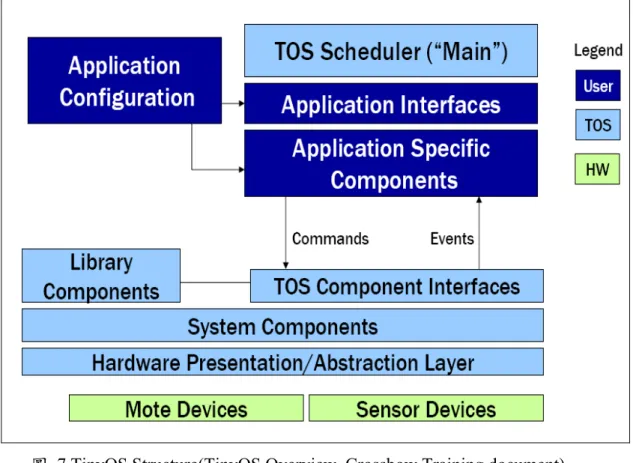
Fig. 2 Architecture of TinyOS ( Crossbow) The Figure 2 shows the architecture of TinyOS. The architecture divide into three parts, are represented by deep blue, light blue and green. The green one means
LIN Tzuhsuan et al TinyOS Tutorial and Experimental Experience for Applying Wireless Sensor Networks in Civil Engineer-ing
3
the hardware device provided by industry, basically consisted with MCU, radio chip, storage chip, and sen-sors. The light blue means the TinyOS core and Firm-ware, this part is also usually provided along with hardware device. The deep blue one is the user defini-tion part, should be modified by researchers. Also the share of components is realized in this part.
Fig.3 The process in TinyOS( Crossbow)
The process in TinyOS could be generally dived into two categories: event and task. Event represents a completed sensor reading, or a RF message received, or any other user specified event. When the event fired, a pre-defined function will be carried out to process this event. This kind of process should be as quick as possible to avoid interference among different events. So some long time desired process are classify as Task will be active when CPU is free, like some data recon-struction and signal process work should be done in Task.
The regular steps of a TinyOS process are as fol-lows:
1. Physical event fired. 2. Event handler signaled.
3. Event parsed and Task posted according to different Event.
4. Event finished 5. Task active 6. Carried Task 7. Task Finished
There are two types of component; module and component. Components is written with code and
wired together as a Configuration to create a Mote ap-plication. The interface provides two methods, “pro-vide” and “use”, to wire the components. The table 1 shows all description of keywords in TinyOS.
Table 1 Description of keywords in TinyOS.
Keword Description
interface A collection of event and
command definitions
module A basic component
imple-mented in nesC.
configuration A component made from
wiring other components.
implementation Contains code & variables
for module or configuration.
components List of components wired
into a configuration.
provides Defines interfaces provided
by a component.
uses Defines interfaces used by a
module or configuration.
as Alias an interface to another name.
command Direct function call exposed
by an interface.
event Callback message exposed
by an interface.
Due to the limited memory, the memory usage and memory space need to be managed. The TinyOS uses the static memory model to manage the memory. The components of static memory model are statically linked together and size required determined at com-pile time. The global variables are used to conserve memory and the pointers are also using here.
TinyOS, the innovation operation system enables re-searchers to implement their own WSN research easily, enables researchers share their code and research result all over the world instead of building everything by oneself, enables an entry level researcher build up a prototype system very easily and quickly. Plenty of component based libraries, supporting mesh protocols, distributed services, data acquisition tools and QoS service, which makes user easy to construct the indi-vidual application with high efficiency and reliability.