IEEE TRANSACTIONS ON MAGNETICS, VOL. 46, NO. 6, JUNE 2010 2397
Adjusting Electrode Potentials to Compensate Thermal/Tissue Effects in
Deep Brain Stimulation via Finite Element Electromagnetic Analysis
Wei-Yi Chuang
1, Paul C.-P. Chao
1;2, and Kuu-Young Young
1Department of Electrical Engineering, National Chiao-Tung University, Hsinchu 300, Taiwan Institute of Imaging and Biophotonics, National Chiao-Tung University, Tainan 711, Taiwan
The proposed method is intended to adjust the electrode potentials used in deep brain stimulation (DBS) with the consideration of both tissue transform and thermal effects caused by stimulation. During a typical DBS process, it is essential, for an effective treatment, to control the stimulation strength and region with varied applied electrode potentials. Some previous studies have been devoted for numerical simulations to find suitable electrode voltage levels for pre-desired stimulated strength and region. These studies consider only one of the two complexity factors due to the intrusion of the DBS lead: 1) a layer of extracellular fluid and giant cell often formed around the DBS leads, called the peri-electrode space and 2) thermal effects. These two factors should both be considered in finite element electromagnetic analysis (FEA), which provides the means to adjust electrode potential for the originally-desired DBS region—called the volume of tissue activated (VTA). Simulation results show that there should be a limiting stimulation voltage to meet the temperature constraint.
Index Terms—Deep brain stimulation (DBS), finite element analysis (FEA), peri-electrode space, thermal effect, volume of tissue
activated (VTA).
I. INTRODUCTION
D
EEP BRAIN STIMULATION (DBS) is a widely-usedapproach to treat varied brain diseases. This approach implants electrodes in a long-term fashion into selected brain targets to treat the symptoms of a number of neurological and other movement disorders, like Parkinson’s disease (PD). Once the electrodes are implanted, an electrode-brain interface (EBI) will be formed. This EBI consists of three main components: the implanted electrode, the layer of peri-electrode space sur-rounding the electrode and the sursur-rounding brain tissue. The peri-electrode space is filled with extracellular fluid at the acute stage during and immediately after implantation. For an exten-sive period of time (chronic stage), the peri-electrode space is eventually filled with giant cells, which are formed pathologi-cally, since the electrode is implanted chronically [1], [2].
During DBS, it is essentially to control the volume of tissue activated (VTA), given certain electrode voltage applied. A sat-isfactory control of VTA is necessary for doctors to restrict the stimulated region to the originally-planned, while keeping other regions intact. Therefore, a number of past studies developed analysis/prediction methods to maintain the desired VTA [2], [3], while considering the aforementioned peri-electrode space at acute/chronic stages. These studies perform varied electro-magnetic numerical analyses to find adjusted electrode voltage to compensate the effects of the growth of the peri-electrode space, often resulting in an increased voltage, due to a lower transfer coefficient of the space. However, these works did not consider that an increased voltage would lead to the temperature increase due to the Joule heat [4]. From hyperthermia therapies [4], a temperature above a certain level C can have neg-ative effects on a single neuron and neuronal network function
Manuscript received October 31, 2009; revised January 24, 2010; accepted March 11, 2010. Current version published May 19, 2010. Corresponding au-thor: P. C.-P. Chao (e-mail: [email protected]).
Color versions of one or more of the figures in this paper are available online at http://ieeexplore.ieee.org.
Digital Object Identifier 10.1109/TMAG.2010.2046399
[6], [7], somehow damaging neurons. Thus, this study investi-gates the dependence between stimulation voltage and thermal effect simultaneously with the prei-electrode space considered, also with the purpose not to exceed the aforementioned critical 38 C. A particular voltage adjustment methodology is proposed to maintain the same VTA at chronic stages as that in acute stage and to consider the thermal effect. The developed method ensures the quality of DBS treatment under the thermal effect consideration.
II. MATERIALS ANDMETHODS A. Model Geometry
An EBI finite element model as shown in Fig. 1 is con-structed and the resulted mesh is also shown in this figure. The model consists of three main components/regions [3], [4]: the implanted electrode, the surrounding brain tissue, and the layer of peri-electrode space. Two types of Medtronic leads, Model 3387 and 3389 DBS leads, are considered in the EBI model simulation. Each of the 3387/3389 DBS leads contains four 1.5 mm-in-length electrodes, the radius of which is 0.635 mm. The only difference between two types of leads is the distance between electrodes (1.5 mm spacing for model 3387 DBS lead while 0.5 mm spacing for model 3389 DBS lead). On the other hand, the brain tissue considered as homogeneous and isotropic material, is modeled as a cylinder surrounding the electrode lead, with 5 cm radius and 14 cm height. The layer of peri-electrode space was defined as 0.25 mm thick, referring to [3].
B. Bio-Heat Transfer Equation
The Pennes bio-heat transfer equation is used to explore the dependence between the stimulation voltage and the corre-sponding temperature in tissue, since it was widely popular in biomedicine [4], [7]. This equation is described as follows:
(1) where , , , and are the mass density, specific heat capacity, thermal conductivity, and temperature of tissue, respectively. In 0018-9464/$26.00 © 2010 IEEE
2398 IEEE TRANSACTIONS ON MAGNETICS, VOL. 46, NO. 6, JUNE 2010
Fig. 1. The electrode-brain-interface model for the 3387/3389 DBS leads. addition, is the blood density, and is the heat capacity of the blood. Finally, represents the body core temperature, is the blood perfusion, is the metabolic heat production in the tissue, and is the external heat source, i.e., the heat gen-eration by DBS. In this work, is in fact , where and are the electrical conductivity of the tissue and the elec-trical potential induced by DBS, respectively, whose settings were based on an experienced EBI model. The technique of the finite element analysis (FEA) method is utilized herein to sim-ulate the bio-heat transfer from the implanted electrodes to its surrounding tissue.
C. Simulation Parameters
Thermal- and electrical-related parameters based on [3], [8] [9], to be used in this study, are listed in Tables I and II, respec-tively. In the bio-heat simulation environment, the initial tem-perature of the brain tissue is set as 37 C, the normal human body temperature. At the acute stage, the peri-electrode space was filled with extracellular fluid (ECF), the value of is 1.7 [S/m]. At the chronic stage, giant cells (GCs) was filled in the peri-electrode space, the value of is 0.125 [S/m], which was obtained from [3]. Prior to obtaining the temperature distri-bution, the Laplace’s equation which follows from the full set of Maxwell’s equation for electromagnetics under the condition that all time-derivatives are zero is used to compute the electrical potential distribution [3]. With solved temperature incorporated the electro-magnetic fields of the EBI model is simulated by using COMSOL Multiphysics 3.5.
III. RESULTS ANDDISCUSSION
The objective of the study is to find the required stimulation voltage adjustment to maintain the same VTA at acute and chronic stages, with a further purpose—not to exceed the aforementioned critical 38 C in the peri-electrode space at both acute/chronic regions. The following are three procedure steps to achieve the simulation of the desired VTA. The first step is to simulate the electric potential distribution after implanting the DBS lead (Section III-A) at acute and chronic stages. The next step is to simulate the temperature distributions for different electric potential values (Section III-B). Finally, the required stimulated voltage is adjusted to achieve the originally-expected VTA by considering the thermal effects (Section III-C).
TABLE I
PARAMETERS OF THEBIO-HEATTRANSFEREQUATION(1/2)
TABLE II
PARAMETERS OF THEBIO-HEATTRANSFEREQUATION(2/2)
A. Electric Potential Distribution
Fig. 2 shows the simulated results about the electric potential distributions after implanting Model 3387/3389 DBS leads. At the initial acute stage, the peri-electrode space was filled with extra-cellular fluid. The specific brain region is stimulated by the voltage 1.561 V, as referring to [5] from medical treatment standards. Through implanting the lead for an extensive period
CHUANG et al.: ADJUSTING ELECTRODE POTENTIALS TO COMPENSATE THERMAL/TISSUE EFFECTS IN DEEP BRAIN STIMULATION 2399
Fig. 2. The electric potential distribution after implanting the DBS leads: (a) and (c) for Model 3387/3389 DBS leads at the actuate stage, respectively; (b) and (d) for the Model 3387/3389 DBS leads at the chronic stage, respec-tively, with the red “axial” line being a cross section as opposed to lead length at certain point of the end electrode, 72.5 mm from lead tip.
of time, the substance content of the peri-electrode space varied from extra-cellular fluid to giant cells. Since the electric con-ductivity of extra-cellular fluid (ECF) is higher than giant cells (GCs), it is often true that the volume of the tissue activated is larger at the acute stage than that at the chronic stage (due to a lower conductivity of GCs than ECF), also as shown in compar-ison between Figs. 2(a), (c) and (b), (d).
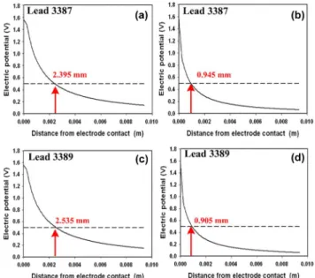
Fig. 3 presents the resulted electric potential distributions for the cross sections at electrodes, along the red “axial” on Fig. 2. We set a hypothetical activation threshold voltage at 0.5 V, as referring to [3] for the critical potential at the boundary of VTA. In results, there should be a difference in the effective VTA be-tween acute and chronic stages. It is seen from the results in Fig. 3(a), (b) that with Model 3387 DBS lead, the distance from the electrode to the tissue activated (the VTA boundary) is 2.395 mm at the acute stage and 0.945 mm at the chronic stage. Under the same situation, it is seen from Fig. 3(c), (d) that the distance from the electrode to the tissue activated was 2.535 mm at the acute stage and 0.905 mm at the chronic stage for Model 3389 DBS lead. Obviously, the volume of tissue (VTA) activated at the acute stage was larger than at the chronic stage. There was the same trend for both DBS leads. It means that if we want to maintain the same VTA level at the acute as chronic stages (i.e., the same quality of DBS treatment), increasing the stimulation voltage at the chronic stage is necessary. However, the quantity of voltage adjustment should be considered to avoid damage of tissue around the electrode due to unavoidable thermal effects. Thus, the next step is to explore the temperature distribution for the required stimulation voltage at the chronic stage, when a higher electrode voltage is required to achieve the same level of VTA as in the acute stage.
B. Temperature Distribution
The stimulation voltage was increased previously to the re-quired level at the chronic stage, such that the VTA could be the same as at the acute stage. Utilizing the essential stimulation voltage, the corresponding temperature distribution was derived from the Pennes bio-heat transfer equation.
Fig. 3. The electric potential distributions at the chosen cross as the red “axial” on Fig. 2: (a) and (c) representing the Model 3387/3389 DBS leads at the actuate stage, respectively; (b) and (d) at the chronic stage.
Fig. 4. (a) The electric potential distribution with the adjusted stimulation voltage of the Model 3387 DBS lead; (b) The corresponding temperature distribution.
Referring to Figs. 3(b) and 4(a), the stimulation voltage for the model 3387 DBS lead at the chronic stage should be in-creased to 3.1 V such that the activated voltage at the distance (from the electrode to the tissue) 2.395 mm can reach the hy-pothetical activation threshold voltage (0.5 V). Moreover, the maximum temperature is also increased to 38.93 C, as shown in Fig. 4(b)—above 38 , which means that the increased tem-perature caused by the stimulation voltage has a negative ef-fect on the brain function. Similarly, Figs. 3(d) and 5(a) present the value of stimulation voltage for the model 3389 DBS lead increased to 3.35 V. As shown in Fig. 5(b), the temperature in-creased to 39.16 C, indicating also a negative effect on the brain function.
In order to avoid unnecessary thermal damages, the appro-priate stimulation voltage should be adjusted by considering thermal effects. Thus, the next step is developed to adjust the appropriate stimulation voltage and avoid the temperature in-creasing to 38 C.
C. Adjusting Stimulation Voltage
Brain function is especially sensitive to the changes in tem-perature. According to previous simulation results, we compre-hended that if the stimulated distance from the electrode to the
2400 IEEE TRANSACTIONS ON MAGNETICS, VOL. 46, NO. 6, JUNE 2010
Fig. 5. (a) The electric potential distribution with the adjusted stimulation voltage of the Model 3389 DBS lead. (b) The corresponding temperature distribution.
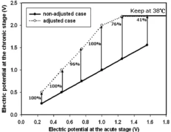
Fig. 6. The original stimulation voltages at the chronic stage vs. those adjusted at the acute stage for Model 3387 DBS lead.
tissue activated is the same as that at the chronic stage, the value of stimulation voltage should be increased. However, the tem-perature should be limited below 38 C for safety consideration. By previous temperature model established, while the stimula-tion voltage is 2.23 V (2.27 V) at the chronic stage, the temper-ature is 38 C. In other words, the stimulation voltage ought to be kept below 2.23 V (2.27 V) at the chronic stage for avoiding brain damage for Model 3387 (3389) DBS lead. Thus, in the ensuing simulations, the stimulation voltage values at the acute stage are set as 0.25, 0.5, 0.75, 1, 1.25, and 1.561 V [5].
Through the similar stimulation potential adjustment as shown in Sections III-A and III-B, Fig. 6 presents the analysis results for Model 3387 DBS lead, showing the original stimu-lation voltage for the acute stage and the adjusted stimustimu-lation voltage for the chronic stage. It is seen herein that if the stim-ulation voltage was approximately less than or equal to 1 V at the acute stage, the stimulation voltage at the chronic stage should be increased as about two times of that at the acute stage to achieve the same VTA. However, if the stimulation voltage at the acute stage is larger than 1 V, each corresponding stimulation voltage value at the chronic stage had to be adjusted to 2.2 V, less than two times, in order to meet the temperature constraint of 38 C. In this case, the VTA is of course less than required. Under the temperature limit (38 C), the required adjustment of stimulation voltage from the acute to chronic
Fig. 7. The original stimulation voltage values at the chronic stage vs. those at the acute stage for Model 3389 DBS lead.
stages is decreased, shown in percentages in Fig. 6. For Model 3389 DBS lead, similar results are shown in Fig. 7.
IV. CONCLUSION
A method is developed in this study to adjust the applied electrode voltage used in deep brain stimulation (DBS) with the consideration of tissue transform and thermal effects caused by stimulation. The adjustment guidelines are distilled from numerical electromagnetic simulations on electrical fields and temperature distribution. According to the simulation results, there is a limiting stimulation voltage to meet the temperature constraint at 38 C.
REFERENCES
[1] A. L. Benabid, S. Chabardes, and E. Seigneuret, “Deep-brain stimula-tion in Parkinson’s disease: Long-term efficacy and safety—What hap-pened this year?,” Curr. Opin. Neurol., vol. 18, pp. 623–630, 2005. [2] C. C. Mclntyre, S. Mori, D. L. Sherman, N. V. Thakor, and J. L. Vitek,
“Electric field and stimulating influence generated by deep brain stim-ulation of the subthalamic nucleus,” Clin. Neurophys., vol. 115, pp. 589–595, 2004.
[3] N. Yousif and X. Liu, “Modeling the current distribution across the depth electrode-brain interface in deep brain stimulation,” Expert Rev. Med. Devices, pp. 623–631, 2007.
[4] C. R. Butson and C. C. Mclntyre, “Role of electrode design on the volume of tissue activated during deep brain stimulation,” J Neural Eng., pp. 1–8, March 2006.
[5] M. M. Elwassif, Q. Kong, M. Vazquez, and M. Bikson, “Bio-heat transfer model of deep brain stimulation-induced temperature changes,” J. Neural Eng., vol. 3, pp. 306–315, 2006.
[6] W. C. Dewey, L. E. Hopwood, S. A. Sapareto, and L. E. Gerweek, “Cellular responses to combinations of hyperthermia and radiation,” Radiology, vol. 123, pp. 463–474, 1977.
[7] B. Bennetts, M. L. Roberts, A. H. Bretag, and G. Y. Rychkov, “Temper-ature dependence of human muscle ClC-1 chloride channel,” J. Physi-ology, vol. 535, pp. 83–93, 2001.
[8] S. Kim, P. Tathireddy, R. A. Normann, and F. Solzbacher, “Thermal impact of an active 3-D microelectrode array implanted in the brain,” IEEE Trans. Neural Syst. Rehabil. Eng., vol. 15, no. 4, pp. 493–501, Dec. 2007.
[9] C. M. Collins, M. B. Smith, and R. Turner, “Model of local temperature changes in brain upon functional activation,” J. Appl. Physiol., vol. 97, pp. 2051–2055, 2004.