JOURNAL OF LIGHTWAVE TECHNOLOGY, VOL. 11, NO. 2, FEBRUARY 1993 343
High-speed Optical Receiver with
Soft Decision
IS1 Cancellation
Pi-Yang Chiang and Ming-Seng Kao, Member, IEEE
Abstract-Due to the stimulating success in developing optical amplifiers, intersymbol interference (ISI) will become the domi- nant limit on both bit rate and transmission distance in long-haul optical fiber communication systems. Here we present a receiver with “Soft Decision IS1 Cancellation” (SDIC) to deal with IS1 in high-speed lightwave systems. The analytical and simulation results show that the transmission distance can be doubled with SDIC. In addition, the receiver with SDIC allows the IS1 cancellation circuit operating with processing and propagation delay much longer than 1-b period. Therefore, it is very promising in very high bit rate optical systems.
I. INTRODUCTION
N the area of optical fiber communications, fiber loss and
I
dispersion are two main constraints on the maximum bit rate and transmission distance. Recently, the problem of trans- mission loss has been significantly relaxed by the introduction of erbium-doped fiber amplifier. Therefore, transmission loss will no longer be a critical issue in system design whereas the intersymbol interference (ISI) caused by fiber dispersion, will be treated as the limiting factor in future long-haul high-speed optical systems.The receiver architecture proposed by Personick [ 11 forces the Fourier transform of the output pulse be of raised-cosine shape. In time domain, the output of the neighboring pulses will be zero at the sampling instant of the decision bit. Hence this equalizer can completely eliminate ISI. However, in order to compensate high-frequency components of the transmitted signal, the zero-forcing equalizer inevitably passes excessive noise components which reduces the signal-to-noise ratio.
Tradeoff between the minimization of noise and IS1 had been made by using Chernoff-Bound approximation to op- timize the equalizer [2]-[4]. The optimization does improve performance analytically, but the resultant filter is too compli- cated to be implemented practically. Furthermore, the filter is linear so it cannot deal with nonlinear distortion in a lightwave channel such as the chirping of a semiconductor laser.
A promising way to cancel both linear and nonlinear IS1 is taking discrete-time electrical signal processing such as maximum likelihood (ML) sequence estimation or decision feedback [5]. The best and well-known ML sequence estima- tion, the Viterbi algorithm, is unfortunately not suitable for high-speed lightwave systems because of limited electronic speed. The nonlinear cancellation (NLC) based on decision
Manuscript received January 15, 1992; revised May 20, 1992. The authors are with the Department of Communication Engineering and the Center for Telecommunications Research, National Chiao-Tung University, Hsinchu, Taiwan, Republic of China.
IEEE Log Number 9204440.
feedback algorithm was introduced by Winters and Gitlin for optical communication systems [ 6 ] . Before deciding a
bit, the NLC detector first estimates total IS1 contributions due to neighbor bits through a lookup table. Second, the IS1 level is fed back to adjust the decision threshold. For every decision bit, the above two steps must be concluded in a time much less than 1-b duration to ensure a correct decision. For optical communication systems with gigabit per second bit rate, however, the bit duration is less than 1 ns. In addition, the feedback switching transients tend to corrupt the input analog signal. Therefore, the NLC circuit is difficult to implement and/or is complicated [7].
In this paper, we present the “Soft Decision IS1 Cancella- tion’’ (SDIC) algorithm to eliminate linear and nonlinear 1%. It has excellent performance and is easy to be implemented at high transmission rate above gigabit per second without much circuit complexity. Unlike the previous NLC technique, the key idea of SDIC lies on the fact that it is not necessary to do IS1 cancellation for every bit, we merely cancel IS1 for those marginal bits near the decision threshold. In other words, whether to do IS1 cancellation or not is soft decided that the IS1 cancellation process- is actuated only when the signal level is near the decision threshold. Therefore, a much longer processing and propagation delay time in the IS1 cancellation circuit is permissible and the cancellation circuit can operate at a lower speed than the transmission bit rate. Thus the present algorithm is quite suitable for high-speed optical systems. The analysis and simulation results show that SDIC can even double the transmission distance while keeping at the same bit error rate (BER).
There are several differences between the NLC technique and the SDIC algorithm. First, the NLC technique continu- ously performs IS1 cancellation for every bit whereas merely marginal bits near the decision threshold are treated in the SDIC scheme. Therefore, the permissible processing time of the SDIC scheme is inherently much longer than that of the NLC technique because the occurrence probability of a marginal bit is very small. Second, the NLC technique can employ multiple decision elements and look-ahead computa- tion to increase permissible propagation and processing delay [7]. However, the circuit complexity increases about L times for L-fold increases in the permissible delay. For the SDIC technique, the permissible delay can be easily extended with little increase in circuit complexity. Third, theoretically the NLC technique will have better performance than the SDIC scheme because the IS1 is canceled for every bit. And the NLC technique works in the presence of large IS1 whereas 0733-8724/93$03.00 0 1993 IEEE
344 JOURNAL OF LIGHTWAVE TECHNOLOGY, VOL. 11, NO. 2, FEBRUARY 1993
U
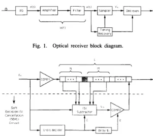
Fig. 1. Optical receiver block diagram.
N
Fig. 2. Decision circuit with soft decision IS1 cancellation.
the SDIC scheme works only when the IS1 is small. However, because the contribution to bit error rate due to IS1 mainly comes from those marginal bits near the decision threshold and the presence of large IS1 is seldom found, the SDIC scheme should have nearly the same performance as the NLC technique in practice.
In Section 11 we show the receiver block diagram and its operation. The performance of the SDIC algorithm is analyzed in Section 111 by evaluating the error probability. Next, a computer simulation is executed to verify the performance and the results are shown in Section IV. Finally, we present conclusions for this paper in Section V.
11. SYSTEM ARCHITECTURE
Fig. 1 shows the block diagram of the optical receiver with SDIC. It is the same as the usual optical receiver except that SDIC is included in the decision circuit. The photodiode (PD) converts the optical power to electrical current and adds noises at the same time. In principle, to minimize noise the impulse response of the transfer function H ( f ) of the cascade of the
amplifier and filter should match the input pulse shape, i.e., a matched filter. However, a matched filter will spread each pulse and increase ISI. Therefore, H ( f ) should be chosen to reduce noise but not to significantly increase ISI. In general, it may be a low pass filter with appropriate bandwidth.
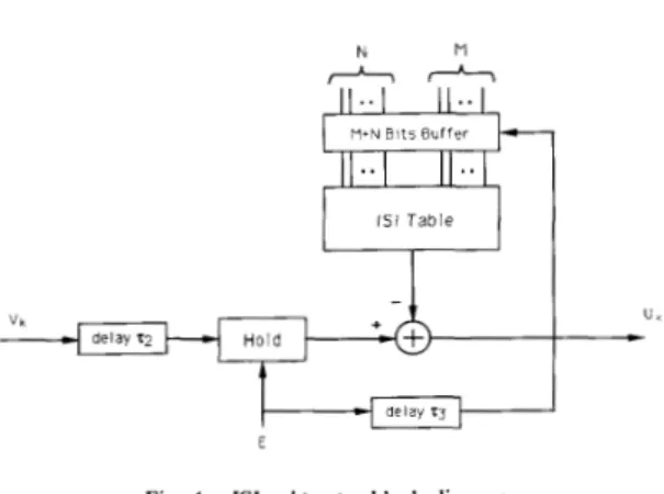
Assume the timing recovery circuit is ideal without jitter, so after sampling, the signal is converted to discrete samples ready for decision. The decision circuit with SDIC is shown in Fig. 2. Above the dashed line is a one-threshold comparator COMPl followed by several shift registers. Below the dashed line is the SDIC circuit which selectively performs IS1 cancel- lation. The SDIC circuit is composed of a U-bit decider, an IS1 subtracter, and another one-threshold comparator COMP2. The operation of the decision circuit is described as follows. As shown in Fig. 2, the k t h sampler is fed into COMPl and the SDIC circuit. The threshold of COMPl is chosen optimally for signals with ISI. The outputs of COMP1, we call them the first decision bits, are stored in the shift registers. On the other hand, the U-bit decider determines whether a
I
I
c o n d i t i o n Ill te s t
-1
-
c o n d i t i o n (21 t e s tFig. 3. U-bit decider block diagram.
bit needs IS1 cancellation or not. If the kth sampler is near the decision threshold of COMP1, it is recognized as an “Undetermined bit” (U-bit), the output of the U-bit decider enables the IS1 subtracter to cancel IS1 from the previous M
and next N neighboring bits, then the IS1 canceled sampler comes to COMP2 to make the second decision. Note that the threshold of COMP2 is chosen optimally for signals without ISI. The second decision then replaces the first decision in the register at the appropriate time. And the delay 71is used
for accurate replacement timing. Otherwise, the Icth bit is recognized as a “determined bit” (D-bit). In this case the SDIC is not actuated and the first decision is unchanged. Thus not all the bits but those near the decision threshold of COMPl need IS1 cancellation and make the second decision. It is because of these marginal bits that the contribution of IS1 of the bit error is very significant, therefore cancellation of IS1 for these bits can significantly reduce bit error probability. Because the SDIC executes IS1 cancellation merely for some specific bits rather than for all the bits, the processing speed can be much slower than the system bit rate and it renders SDIC suitable for high-speed lightwave systems.
The heart of the SDIC circuit is the U-bit decider. Its block diagram is shown in Fig. 3. There are two threshold levels: T h H for high threshold level and ThL for low threshold level. T h H is higher than T h l , the threshold of COMP1, and ThL is lower than T h l . The optimal T h H and ThL can be determined for a particular signal power, ISI, and noise. The optimization will be discussed later. The U-bit decider determines which bit needs further processing based on the following two test conditions:
1) The sampled signal level is between ThL and T h H . 2) Neither of the previous M bits satisfies test conditionl). The first test, which is the key idea of SDIC, is to examine which is a marginal bit. The second test is to prevent from successive IS1 cancellations and to provide a much longer time than a bit period for processing and propagation delay through the cancellation and replacement path. By increasing M , one
can force the IS1 cancellation circuit to operate at a desired slow speed with little performance degradation.
A decision bit with sampled level V k , if both conditions are
true, is marked as U-bit, and the IS1 cancellation circuit begins to work. Otherwise, the bit is marked as a D-bit and the SDIC does nothing if any of the two conditions is false.
345
CHIANG AND KAO: HIGH-SPEED OPTICAL RECEIVER
ThH is the threshold of “1” (high-level signal) and T h L
is the threshold of “ 0 (low-level signal). If v k is greater than
T h H , the Icth bit is definitely judged as a “1.” We can choose
ThH high enough that the probability of v k being greater than
ThH is extremely small when a “0” is sent. Similarly, if v k is smaller than T h L , the error probability that it represents
a “0” is also extremely small. We mark these two kinds of the sampled signal as D-bits without question. For bits for which condition 1) is true but condition 2 ) is false, the IS1 cancellation circuit will also not be enabled in order to provide enough time for the cancellation process and to prevent error propagation. So we mark them as D-bits as well. If there are
successive bits located between T h L and T h H , all bits except
the first are marked as D-bits so as not to interrupt the IS1
cancellation process of the first bit. The reason that condition
2 ) prevents error propagation is explained below. If a U-bit
is detected, none of the previous M bits may be U-bits. That
is, we find IS1 contribution of the decision bit merely by the estimates of the previous M bits which are all D-bits and
unchanged by SDIC. Thus error propagation may occur only when some estimates of the D-bits are wrong. As discussed earlier, however, the error probability of a D-bit is extremely small. Consequently, there is nearly no error propagation with test condition 2). It is not necessary to consider the next N bits
here because their IS1 contributions are fed forward instead of backward. If the bit in process is a U-bit, and some of its next N bits are also located in the marginal region, the IS1
cancellation process starts regardless of the marginal bits. And when the bits come into the U-bit decider, they will be marked as D-bits due to the preceding U-bit.
The U-bit decider classifies bits into D-bits and U-bits. For a D-bit, the decision of COMPl is kept unchanged. If a sampled
signal is classified to be a U-bit, IS1 subtracter begins to work. The block diagram of IS1 subtracter is shown in Fig. 4. It is made up of an IS1 lookup table, a buffer, a holder, and an adderhubtracter. All the linear and nonlinear IS1 caused by the
M
+
N neighbor bits can be predetermined and stored in the table. Therefore, total IS1 contributions of the previous M andnext N bits can be subtracted from the sampled signal v k . The buffer and the holder are used to holding the first decisions, or estimates the M
+
N neighbor bits and the sampled signal during the subtraction process, respectively. The delays 7 - 2 , ~ are used for accurate subtraction. The delay rz is adjusted for holding the correct sampled signal which waits for IS1 subtraction. The delay 7-3 is adjusted for holding the correct neighbors of the U-bit.Note that not every bit need to be further processed; and if any need, the time between this and the last IS1 cancellation is at least of M - bit duration time (usually much more than
that). This characteristic is very promising when the receiver is operated at very high speed. Only the COMP1, the shift registers, and the U-bit decider must operate at the speed of the transmission bit rate, the other circuits may operate at a much lower speed.
N M
M * N B l t s B u f f e r
Fig. 4. IS1 subtracter block diagram.
probability is evaluated by statistical analysis. In the next section, we will carry out computer simulation to verify the analysis. Results of both show that a receiver with SDIC indeed can effectively improve system performance.
A receiver with SDIC is a nonlinear system. To evaluate the error probability, we consider a bit with its previous M and next N bits as a bit block, and find the error probability of the bit for all the combinations of the binary-bit pattern in the block. Because every bit has its block with length M
+
N+
1 , the average error probability is the estimate of BER.The filter output can be written as
+ E
v ( t ) = d i p ( t - ZT)
+
n ( t )a = - c c
where n ( t ) is the effective noise, d; is the binary data for the
ith bit, and p ( t ) is the pulse shape.
By merely considering the IS1 induced by previous
M
and next N bits, the discrete-time sampler att
= kT isk+N
i = k - M
if k
where P = p ( 0 ) is the signal level of the decision bit.
1, = p(kT - i T ) , i
#
k , is the IS1 level contributed by the i t h bit att
= IcT,nk = n ( k T ) is the sample of n ( t ) att
= IcT, M is the number of the previous bits which generate IS1 to the decision bit, and N is the number of the next bitswhich generate IS1 to the decision bit. Assume all the bits are equally probably as “1” or “0,” then the error probability of the first decision is readily given as
1
2
Pe,first = -[Prob(Vk
>
Thl)dk = 0)+Prob(Vk
<
Thlldk = l)]. (3)The error probability with SDIC, denoted as P e , s ~ 1 ~ , de- pends not only on the sample at
t
= kT but also on thefirst decisions of the neighbor M
+
N bits because of the IS1 subtraction.111. PERFORMANCE EVALUATION
Define the general neighborhood bit pattern set Dk as
We evaluate the Derformance of SDIC bv both statistical
I
I
probability with SDIC can be expressed as
1 1
Pe,SDIC =
2M+N
z[PeOD f pel01 (5)346 JOURNAL OF LIGHTWAVE TECHNOLOGY, VOL. 11, NO. 2, FEBRUARY 1993
when d k = 1 and its neighbors are D . P e 0 ~ can be further written as
P,OD = Prob ( v k
>
ThHIdk = 0)+Prob(Vk+i E (ThL,ThH)3i E { l , . . . , M } , Vk E (Th1,ThH)Jdk = 0) + P r o b v k + i $! (ThL,ThH)Vi E { l , . . . , M } , Vk E (Th1,ThH) k+N v k
-
(
(6) diIi>
Th2ldk = 0 i=k-M i # kwhere di is the first decision of the i t h bit.
There are three terms in the right-hand side of (6). The first term is the probability that as “0” is sent, the sampled signal v k is already greater than the high threshold level ThH. The
second term is the probability that as “0” is sent, some of the previous M samples locate between ThL and ThH and v k is greater than T h l but smaller than ThH. In this case, though
v k is near the threshold T h l , the U-bit decider does not mark
it as a U-bit. Therefore the second decision is not made and the final decision is wrong. The third term is the probability that as “0” is sent, the kth bit is marked as a U-bit, but the output of the IS1 subtracter is still greater than Th2. Although
Fig. 5. Probability density function of Vk .
where P,OD and P u l ~ are the probabilities that the kth bit is classified as a U-bit with neighborhood pattern
D
and d k = 0 , 1 respectively. They can be easily written asP u o ~ = Prob ( v k + ; $! (ThL,ThH)Vi E { l , . . . , M } ,
Vk E (ThL, T h H ) d k = 0
1
vk
E (ThL, T h H ) dk = 1 ) .(9)
PulD = Prob ( v k + i $! (ThL,ThH)Vi E { l , . . . , h f } ,
(10) In general, the probabilities Pe,first, P e , s ~ l c 1 and P, depend on the bit pattern set
D ,
IS1 level, and noise distribution, which are difficult to be analytically expressed. Here for illustrative purpose, we find them for a simplified case. For a decision bit, consider the IS1 generated merely by the preceding 1 band next 1 b with the same contributions. Namely, M = N =
1,Dk = {dk-i,dk+i}, and
I , i = k - l , k + l
0, others. Then v k is given as
the first decision is replaced, the second decision by COMP2
is still wrong. Note that the effect of IsI due to the previous and next bits is included in vk (by ( 2 ) ) in all the above three terms.
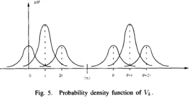
Further assume the effective noise to be Gaussian distributed with variance
02.
The mean ofvk
varies for different combina- tions of d k - 1 , d k , and d k - 1 . The probability density function (pdf) of v k is shown in Fig. 5.Clearly, from the pdf of Vj the optimal threshold of COMPl
Similarly, PelD can be further written as
PelD = Prob
(v,
<
ThLldk = 1 ) should be chosen as(13) P + 2 1 P 2 - - + I . T h l =
-
-
+Prob(Vk+i E (ThL ,Th H)Ii E { l , . . . , M } , v k E (ThL,Thl)ldk = 1 ) 2Define the Q function as
(14)
l o o
v k + i $! (ThL,ThH)VZ E { l , . . . , M } ,
Q(y) =
-
1
exp ( - ; ) d x .v k E (Th L,T hH) fill
Thus the error probability of the first decision is
1 T h l - I
(7)
Pe,first
=f0(%)
+
4~(o,)
The other parameter of interest is the occurrence probability of the U-bit. It can be written as
P + I - T I L )
+
( P + 2 f ; T h l )-Q
+
tQ(
onCHIANG A N D KAO: HIGH-SPEED OPTICAL RECEIVER 341
I
0 I
Th2 P
Fig. 6. pdf of U k if IS1 is correctly canceled.
By (13), it can be simplified as
Pe,first =
a~(,)+5~(,-)+a~(T)-
1 T h l 1 T h l - I 1 T h l - 2 1(16) Note that Pe,first is in fact the error probability of an usual receiver with optimum decision threshold.
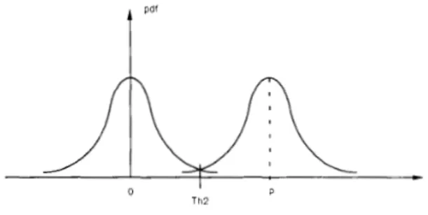
Now we consider the error probability with SDIC. If all the IS1 are correctly canceled, the IS1 subtracter output u k becomes ISI-free with pdf as shown in Fig. 6. Therefore, the optimal threshold of COMP2 is
(17)
P Th2 =
-.
2
The probabilities P e o ~ and Pel, are in general pattern-
dependent. For example, let d k - 1 , d k , d k + l be 1, 0, 1, re- spectively, i.e., d k = 0 , D = ( 1 , I } , then Peo{l,l} is as
given by (18), shown at the bottom of this page, where
A T h = i ( T h H
-
T h L ) is a half of the deviation betweenthe two thresholds, and min ( a , b) denotes the smaller one of a, b. The first and second terms of (18) arise from the first and second terms of (6), respectively. And the last four terms are generated by the third term of (6). All the error probabilities
for any other combinations of d k - 1 , d k , d k + l can be found similarly. The average of all these probabilities is the estimate of BER.
The probability that the kth bit is a U-bit for d k = 0,
D
= { 1 , 1 } isIn the above equation, the right-hand sides consist of two product terms. The first product term is the probability that the (k-1)th bit is not located between ThL and ThH. The second term is the probability that the kth bit is located between
T h L and ThH. The probabilities for other combinations
of & - I , d k , d k + l can be found similarly. The overall U-bit occurrence probability is the average of these probabilities.
In the following discussion, we assume the transmitted pulse be an ideal square pulse stream in NRZ format. The optical fiber is modeled as a linear filter with impulse response
where ~f is the time for light to travel through the fiber,
U F is the root mean square pulse width of the impulse. For convenience, we use a normalized root mean square pulsewidth of equal to O F / T , where T is the bit duration. The
response of the amplifier and the filter are jointly modeled as a Buttenvorth filter with bandwidth SW, and for simplicity, a
normalized bandwidth bw equal to B W
*
T is used instead ofThH - 21 P
-
ThH P + I - ThH)
- Q ( p + l - T h L ) ] } PeOtlJ1 = Q ()+;{
[Q()I
on(-
).
+ [Q( on O n x[ ~ ( y )
- Q ( ~ ' : ; ~ I ) ]+;{
[ l - Q ( P - on ThH) ]
+
[ l - Q ( P + I - T h H ) ] } an x:{
2 [l-Q(=$>]+
[ l - Q ( P + I u - T h H ) ] }[o(
Th2+
I+
min ( A T h , I ) - 2 1)
-Q
("t;
' I ) ] on P - ThH + ' { [ i - ~ ( 2) ] + [ i - Q ( p + l o i T h H ) ] } x ; { [ o ( ~ ) ] + [ Q ( P + ' - T h H ) ] }
gnx
[o(Th2::-21)
-Q("":r2")]
+:{
[o(p-o:hH)]
+
[Q(P+'gi*hH)]}
x L { [ l - Q ( F ) ] + [ l - V ( 2 P + I - T h H ) ] } on X
[
Q( T h 2 + 1 - 2 1 ) on -Q
(
Tht:
' I ) ]+:{
[Q(p-u:hH)]+
[ Q ( p + ' u ~ T h H ) ] } x:{
[Q(F)]
+
[ Q ( p + l u ~ T h H ) ] } Th2+
I+
min ( A T h , I ) - 2 1' I 10.' 10-5 348 ,/. ,_.'. - ,_I,. - /" - _,/ 10-4
,
, ,.
, , , , , ,,
JOURNAL OF LIGHTWAVE TECHNOLOGY, VOL. 11, NO. 2, FEBRUARY 1993
10-2
I O V ' I ' ' ' ' ' 5 , ' I
0 0 0 2 0 0 4 0 0 6 0 0 8 0 1 0 1 2 0 1 4 0 1 6 0 1 8 0 2 dTh
Fig. 7. P,,SDIC versus dTh with bu! = 0.5. 0 1 1 0.08 -
E
0.07 0.06 - 0.05I
0.04L
0 1 0.15 0.2 0.25 0 3 0.35 0.4Fig. 8. dTh* versus u f with bw = 0.5.
BW. We further define a parameter dTh as
1
dTh = -(ThH 2
-
T h L ) / P (21) which is half the deviation between ThL and ThH normalizedby P.
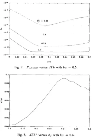
Fig. 7 shows the error probabilities with SDIC as a function of dTh for different af with bw = 0.5. When dTh = 0, there will be no U-bit detected, and the first decision of every bit is kept unchanged. In this special case, P e , s ~ l c is equal to Pe,first and is the error probability of an usual receiver without SDIC. As dTh increases, the IS1 cancellation circuit begins to
work, P e , s ~ l c decreases as expected. There exists an optimal
dTh, beyond which P e , s ~ l c does not decrease but increases instead. As dTh becomes too large, the probability that a bit
locates between T h L and ThH increases, by test condition 2)
of the U-bit decider, the number of U-bits may decrease, and the IS1 cancellation circuit works less frequently.
There exists an optimal dTh, dTh*, to reach the minimum
error probability. Fig. 8 shows that dTh* varies with of.
For small af,dTh* increases with of extending the IS1 cancellation process. When a f becomes large, the probability
of wrong IS1 cancellation increases, dTh* therefore decreases.
To demonstrate the excellent performance of a receiver with SDIC, the error probabilities Pe,first, P,,SDIC versus a f are shown in Fig. 9. The upper curve is Pe,first, the error probability of an usual receiver. The lower curve shows
P e , s ~ l c , the error probability of the receiver with SDIC. Let
of be linearly proportional to the system transmission distance,
I
0.1 0 15 0.2 0.25 0 3 0.35 0.4
Fig. 9. Pe,first and P,,snlc versus af with bw = 0.5
the receiver with SDIC can nearly double the transmission distance at BER = and extends half of the transmission distance for BER =
lo-'.
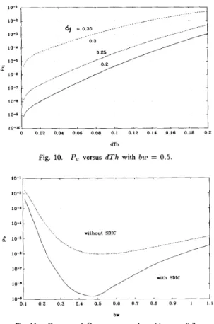
If longer distance is not needed, the SDIC receiver can substantially reduce error probability. For a f = 0.3, as an example, the receiver with SDIC can reduce error probability by nearly three orders of magnitude (from lop6 to lo-'). Note that as af increases, the difference between Pe,first and P e , s ~ l c imreases because the receiver with SDIC cancels ISI. Unfortunately, the improvement by SDIC decreases as IS1 becomes large due to the incorrect IS1 cancellation processes. This is different from that of continuous-time equalizer.Another major advantage of the SDIC algorithm is that the IS1 cancellation circuit can operate at a lower speed than the transmission bit rate when optimal dTh is chosen. Because one
U-bit occurrence represents one IS1 cancellation process, let us consider the characteristic of U-bit occurrence probability
(P,). Fig. 10 shows P,, versus dTh for different af. It is reasonable to assume that the increase of P, with the increase of dTh means that the rate of the IS1 cancellation process
increases as well. If dTh is kept fixed, larger uf creates more
sampled signals located between T h L and ThH, hence, it
results in larger P,. From Fig. 8, the optimal dTh is usually
less than 0.1. It is apparent that P, is of a lower order than
Namely, the IS1 subtraction circuit can work at a lower rate than the transmission bit rate, which is suitable for high- speed receivers. In the next section, we will show that one can force the subtraction circuit to operate at a desired low speed with little performance degradation. In addition, the IS1 cancellation is very efficient. Notice when a f = 0.3, it can decrease error probability by nearly three orders of magnitude by merely doing IS1 cancellation 1/1000 of the transmitted bits. This means after IS1 cancellation, most error bits can be recovered.
Next let us consider the effect of filter bandwidth. The noise in the receiver is dominated by circuit noise or shot noise and both can be approximated as additive white Gaussian noises [6]. If a large bandwidth is chosen, although the IS1 can be minimized, the effective noise increases. On the other hand, small bandwidth will result in significant ISI. Hence there exists a tradeoff between noise and ISI. This is shown in Fig. 11 with af = 0.3. The upper curve is Pe,first and the lower curves shows P,,SDIC. It is clear that the optimal bandwidth of
I 10-1 10-2 ',,, 10-4 - 2 1 0 - 5 - 10-8 - /./--. without SDIC .~..-- .__. ..-- .-.- ~ -... --- --- ... ~~~ ... ~ .... --.--- --.. %_ ,.., 349
CHIANG AND KAO: HIGH-SPEED OPTICAL RECEIVER
intensity modulation/direct detection system with transmission bit rate of 2.4 Gb/s through a single-mode fiber. A pseudo- random binary data stream is generated by shift registers with length 7. The stream contains all bit patterns with length 7 which is enough for IS1 generation. A total of
lo9
b have been transmitted. In the transmitter, the laser driving current pulse is modeled in the NRZ form asi 10-7 10 8 -
3
w i t h SDlC t < O - b rFig. 11. Pe,first and Pe,snlc versus bui with af = 0.3.
Pe,first is 0.52 and 0.48 for P e , s ~ 1 c . The optimal bandwidth
for P e , s ~ 1 c is slightly smaller than that for Pe,first because
the SDIC algorithm enhances IS1 cancellation capability, the optimal bandwidth would like to reduce noise while allowing more ISI. Consequently, the resulting bandwidth is smaller. On the left side of the optimal bandwidth, the performance is degraded by ISI; and on the right side, the performance is degraded by noise. Fig. 11 shows that the optimal bandwidths for Pe,first and P e , s ~ l c are nearly the same. If an usual receiver is operating at its optimal filter bandwidth for lowest error probability, the SDIC algorithm can significantly reduce the error probability while keeping about the same bandwidth.
Iv. COMPUTER SIMULATION
In the preceding section, we evaluated the performance of the SDIC receiver by statistical analysis. However, real lightwave systems are nonlinear, for example chirping in high- speed modulation of a semiconductor laser may result in nonlinear IS1 which is pattern-dependent. Therefore, statistical analysis can only approximately predict system performance. To understand the performance of the SDIC receiver in the presence of light-source nonlinearity and the accuracy of analytical results, in this section we carry out computer simu- lations taking into account a practical laser model.
In the simulation, each function block in the system is modeled by computer and the overall system is a cascade of each model in sequence. The example we take here is an
( t
- T ) 2Ib
+
L e x p(-+
t>
Twhere Ib is the bias current, I,,, is the peak modulation current,
t,
is the pulse rise time, and T is bit duration equal to 417 ps[8]. Here Ib,
I,,
andt ,
are taken as 38 mA, 28 d, 100 ps,respectively. The optical pulse of the semiconductor laser is obtained by solving the rate equation with the same parameter as in [8]. Hence the nonlinear distortion induced by high-speed modulation of the diode laser can be simulated. The optical fiber is modeled as a linear filter with impulse response as in (20). In the receiver, the amplifier and the filter are again modeled as a Butterworth filter with normalized bandwidth bw and the overall noise is Gaussian distributed.
Fig. 12 shows the BER as a function of dTh with a f = 0.35. The solid line is the analytical result and the circles are simulation results. The deviation between the analytical and simulation results comes from the linear channel and equal IS1 contributions of neighboring bits assumed in the analysis. Both results indicate that there exists an optimal
dTh to get minimum BER. We further see that the analytical
result is close to the simulation result, i.e., that the analytical expressions can appropriately evaluate system performance even in the presence of nonlinear distortion. Fig. 13 shows
P, with respect to dTh with af = 0.35. It is obvious that the analytical formula is very close to the simulation result. Because the number of U-bits is much larger than that of error bits, therefore the analytical expression of P, comes
closer to the simulation result than that of P,, From the above figures, it can be found that the analytical results provide an accurate estimate of U-bit occurrence and are close to BER
JOURNAL OF LIGHTWAVE TECHNOLOGY, VOL. 11, NO. 2, FEBRUARY 1993 350 / - analytical 0 0 0 2 0 0 4 0 0 6 0 0 8 0 1 0 1 2 0 1 4 0 1 6 0 1 8 0 2 dTh 10-5
Fig. 13. Analytical and simulation results: P, versus dTh with bur = 0.5.
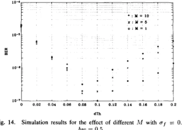
10-5 m . a * 0 1 . 10-7 0 0 0 2 0 0 4 0 0 6 0 0 8 0 1 0 1 1 0 1 4 0 1 6 0 1 8 0 2 dTh
Fig. 14. Simulation results for the effect of different M with uf = 0.3,
bur = 0.5.
of simulation results. Therefore, the analytical formula can be used to determine the optimal dTh and to estimate the error
probability of the receiver with SDIC.
Note that P, is also the occurrence probability of the IS1
cancellation process. For P, = on the average we just have to do one IS1 cancellation per
lo3
b. However, because the U-bit occurs randomly, the real processing speed should be faster than a 10-3-b rate. By the test condition 2 ) of the U-bit decider, the cancellation process is actuated at most once per M
+
1 b. Thus the permissible processing time of the cancellation circuit is extended to M+
1 b duration. But if two U-bits occur within M+
1 b then one of them will be ignored and judged as a D-bit without a second decision. Therefore, the BER is expected to increase with M . the simulation resultsof Fig. 14 show how BER’s vary with dTh for different M .
At the optimum dTh, the BER for M = 5 is slightly larger
than that for M = 1. And the BER for M = 10 is still on the same order as that for M = 1. Therefore, we can easily extend the permissible delay of the cancellation circuit with little performance degradation, which renders SDIC a promising scheme to implement IS1 cancellation in high-speed lightwave systems.
V. CONCLUSION
In this paper, we present a receiver with “Soft Decision IS1 Cancellation” to deal with IS1 problem in high-speed optical
systems. The major constraint in treating the IS1 problem of high-speed receivers is the limited processing speed. Here the SDIC receiver can easily relax this limitation by doing IS1 cancellation merely for some marginal bits but not for all bits, therefore the cancellation circuit can operate at a desired lower speed than the transmission bit rate with little performance degradation. Additional features of the present receiver include: 1) the IS1 is treated by discrete-time signal processing instead of continuous-time equalization, 2 ) both linear and nonlinear IS1 can be canceled, and 3) there is nearly no error propagation. Both statistical analyses and computer simulations are carried out to evaluate the system performance. The results show that the SDIC receiver can nearly double the transmission distance at BER = and for fixed distance, it can decrease the BER by approximately three orders of magnitude.
REFERENCES
S. D. Personick, “Receiver design for digital fiber optic communication systems,” Bell Syst. Tech. J., vol. 52, pp. 843-874, July-Aug. 1973. G. F. Hermann, “Linear detection in a Poisson regime with random pulse heights,” IEEE Trans. Commun., vol. COM-24, pp. 254-259, Feb. 1976. K. E. House, ‘‘Filters for the detection of binary signaling: Optimization using the Chernoff bound,” IEEE Trans. Commun., vol. COM-28, pp. 257-259, Feb. 1980.
J. R. F. da Rocha and J. J. O’Reilly, “Linear direct-detection fiber-optic receiver optimization in the presence of intersymbol interference,” IEEE
Trans. Commun., vol. COM-34, pp. 365-374, Apr. 1986.
R. E. Blahut, Digital Transmission of Information. New York Addison- Wesley, 1990.
J. H. Winters and R. D. Gitlin, “Electrical signal processing techniques in long-haul fiber-optic systems,” IEEE Trans. Commun., vol. 38, pp. 1439-1453, Sep. 1990.
S. Kasturia and J. H. Winters, “Techniques for high-speed implementa- tion of nonlinear cancellation,” IEEE J. Select. Areas Commun., vol. 9, pp. 711-717, Jun. 1991.
J. C. Cartledge and G. S. Burley, “The effect of laser chirping on lightwave system performance,” J . Lightwave Technol., vol. 7, pp. 568-573. Mar. 1989.
Pi-Yang Chiang was born in Taipei, Taiwan, Re- public of China, on March 22, 1968. He received the B.S. degree in electrical engineering from National Taiwan University, Taiwan, in 1990, and the M.S. degree in communication engineering from National Chiao Tung University, Taiwan, in 1992.
He now serves in the army of the R.O.C. on a tour of duty from 1992 to 1994. His current interests are in the areas of optical communication systems and computer communication networks.
Ming-Seng Kao (S’89-M’90) was born in Taipei, Taiwan, R.O.C., in 1959. He received the B.S.E.E. degree from the National Taiwan University, in 1982, the M.S. degree in optoelectronics from the National Chiao-Tung University, in 1986, and the Ph.D. degree in electrical engineering from the National Taiwan University, in 1990.
From 1986 to 1987 he was an Associate Re- searcher at the Telecommunications Laboratories, Chung-Li, Taiwan, where he worked on optical fiber communication systems. Since February 1990 he has been with the Department of Communication Engineering at the National Chiao-Tung University. He is currently interested in multiwavelength optical networks and photonic switchings.