High-Efficiency Polymer Light-Emitting Diodes Using Neutral Surfactant Modified
Aluminum Cathode
Yu-Hua Niu and Alex K.-Y. Jen*
Department of Materials Science and Engineering, Box 352120, UniVersity of Washington, Seattle, Washington 98195
Chingfong Shu
Department of Applied Chemistry, National Chiao-Tung UniVersity, Hsin-Chu, Taiwan ReceiVed: June 23, 2005; In Final Form: January 10, 2006
High-efficiency polymer light-emitting diodes were fabricated by inserting a layer of nonionic neutral surfactant between the electroluminescent (EL) layer and the high-work-function aluminum cathode via spin coating. It was found that both the poly(ethylene glycol)- and poly(propylene glycol)-based surfactants as well as their copolymers can all demonstrate similar performance enhancement. Device performances comparable to or even better than those of the control devices using calcium as the cathode have been achieved for both poly-(p-phenylene)-based and polyfluorene-based conjugated polymers with orange-red, green, and blue emission colors. It is possible that when both surfactant and aluminum are used as the cathode, the abundant hole injection through a hole-transporting layer and hole pile-up at the inner side of the EL/surfactant interface might cause an effective electric field to induce the realignment of the dipole moment of those polar surfactant molecules, thus lowering the barrier for electron injection. In addition, the coordination between the aluminum and oxygen atoms on the surfactant might cause n-type doping in the areas near surfactant in the EL polymer layer that causes the enhancement of electron injection.
Introduction
Great attention has been attracted in industry and academia since the first demonstration of polymer light-emitting diodes (PLEDs) in 1990 due to their potential applications in large area flat-panel displays and low-power-consumption white light illumination.1,2Efficient and balanced charge injection from both the anode and the cathode into the electroluminescent (EL) layer is very important for achieving high-performance polymer LEDs. The common approach to realizing efficient electron injection is to employ a low-work-function metal such as calcium or barium as the cathode and then protect it by depositing a stable metal like aluminum or silver on top of them.3-6 These low-work-function metals are highly reactive and tend to create detrimental quenching sites at areas near the interface between the EL layer and cathode. The mobile metal ions formed during the cathode evaporation process could also affect the long-term stability of the devices.7To tackle these problems, a layer of ultrathin “insulating” compound, such as lithium fluoride (LiF) or cesium fluoride (CsF), was used as an electron-injection buffer between the EL layer and a high-work-function aluminum (Al) electrode.8,9The devices fabricated in this way showed rather promising results, with the performance being equal to or even exceeding those achieved using Ca as the cathode. This strongly stimulates the interest to investigate the underlying mechanisms that cause the improved electron injection.10-12 Considering that the thickness of this ultrathin layer is generally less than 1 nm and is strongly dependent on the cathode metal used,13,14it is hard to believe that such a thin layer only functions as an insulating layer. The evidence obtained from X-ray photoelectron spectroscopy (XPS) experi-ments indicates that LiF or CsF may dissociate into ions initially
and then the low-work-function metal ions migrate into the EL layer, doping the material and lowering the electron-injection barrier.15,16 This would create the same problem faced when using the active metals mentioned above as the cathode due to the diffusion of these metal ions.
Recently, several papers report significantly improved electron injection of high-work-function Al cathodes by using either soluble metal-ion-containing polymers or surfactants.17-21It was believed that the metal ions contained in the interlayer or in the surfactant additives are essential to the enhanced EL performance. However, new experimental results showed that the metal ions are not a prerequisite for this. For example, efficient polymer LEDs have also been achieved by blending 10% poly(ethylene glycol) (PEG),22a non-metal-ion-containing surfactant, into the EL polymer and using Al as the cathode. Believing that the key to improve the LED performance lies in the interfacial modification between the EL layer and Al, we investigated the feasibility of using similar materials simply as an interfacial charge-injection layer.
In our previous communication,23 we found that highly efficient polymer LEDs can be achieved simply by spin coating a layer of nonionic neutral surfactants from their solutions either in water or in other polar solvents on top of the EL polymer layer and using Al as the cathode. We demonstrated the results by using orange-red-emitting poly[2-methoxy-5-(2′ -ethylhexyl-oxy)-1,4-phenylenevinylene] (MEH-PPV) as the EL polymer and with polyoxyethylene(12) tridecyl ether (P12TE) as the neutral surfactant. The device with the P12TE/Al cathode reached a higher performance than that of the control device using Ca/ Al as the cathode.
In this paper, we report the progress of applying the neutral surfactants to other polymer LEDs with blue or green emission. We also expanded the list of the neutral surfactants by using * Corresponding author. E-mail: [email protected].
10.1021/jp053426e CCC: $33.50 © 2006 American Chemical Society Published on Web 03/09/2006
compounds with different segment lengths. By using all homologous compounds with a general chemical formula, CmH2m+1(OCkH2k)nOH, and their copolymers with a high enough molecular weight to form thin films, similar performance enhancement can also be achieved. In addition, it was found that, by using the triblock copolymers of poly(ethylene oxide) [(EO)x] and poly(propylene oxide) [(PO)y] with the general formula (EO)x(PO)y(EO)x, very promising long-term stability can also be realized as a result of the increased glass-transition temperature (Tg) by adding the hard (PO)ysegments as well as the increased molecular weight. In-depth understanding of the mechanisms is also elucidated by comparing the performance of devices with neutral surfactants as the interfacial modification layer to that of devices with only a layer of short-chain polar molecules with only one hydroxyl end group as well as that of devices with a layer of nonpolar molecules composed of pure alkyl chains.
Experimental Section
All of the commercially available poly(ethylene glycol) (PEG)- or poly(propylene glycol) (PPG)-based nonionic surf-actants, polyoxyetholene(6) tridecyl ether (P6TE, m ) 13, k ) 2, n∼ 6), polyoxyetholene(12) tridecyl ether (P12TE, m ) 13, k ) 2, n∼ 12), poly(ethylene glycol) hexadecyl ether (BJ76, m ) 16, k ) 2, n∼ 10), poly(propylene glycol) (PPG, k ) 3, Mn∼ 1000), and poly(propylene b-poly(ethylene glycol)-b-poly(propylene glycol) (PEP, Mn ∼ 2000) were purchased from Sigma-Aldrich. A triblock copolymer of poly(ethylene oxide) [(EO)x, k ) 2] and poly(propylene oxide) [(PO)y, k ) 3], (EO)106(PO)70(EO)106(EPE), with a higher molecular weight, Mn∼ 13 000, was provided by BASF Chemicals. As contrasts to understand the mechanisms, 1-octadecanol (m ) 18, n ) 0) and octadecane were purchased from Sigma-Aldrich also. The chemical structures of the above-mentioned neutral surfactants and chemicals for contrast are shown in Scheme 1.
Light-emitting conjugated polymers with three representative colors such as MEH-PPV (orange-red), poly[2-(2′-phenyl-4′,5′ -bis(2′′-ethyl-hexyloxy)phenyl)-1,4-phenylenevinylene] (P-PPV) (green), and [poly(9,9-bis(4-di(4-n-butyl-phenyl)aminophenyl))- stat-(9,9-bis(4-(5-(4-tert-butylphenyl)-2-oxadiazolyl)-phenyl))-stat-(9,9-di-n-octyl-fluorene)] (PF-TPA-OXD) (blue) were cho-sen. They were all synthesized according to the published procedures, and their chemical structures are shown in Scheme 2.24-27
The LEDs were fabricated on indium tin oxide (ITO) covered glass substrates. A layer of polyethylene dioxythiophene polystyrene sulfonate (PEDOT:PSS, Bayer AG) film (40 nm) was spin coated on precleaned ITO as the hole-injection anode buffer. After the PEDOT:PSS layer was vacuum-dried, the substrates were moved into a glovebox filled with circulated argon for protection and all the subsequent device fabrication processes were done under this inert circumstance. A layer of light-emitting conjugated polymer, with a nominal thickness of 80 nm, was then spin coated on top of the PEDOT:PSS layer. An ultrathin layer of neutral surfactants or 1-octadecanol with a thickness of less than 10 nm was spin coated from their solutions in 2-ethoxyethanol, which will not cause erosion of the underlying EL layer. For octadecane, hexane was used as the solvent to ensure a good solubility and that no erosion to the underlying EL layer would occur. Finally, Al (200 nm) was evaporated as the cathode under vacuum (<1× 10⁻⁶ Torr). For the control devices, a layer of Ca (20 nm) was evaporated before the evaporation of Al. On each substrate, five LEDs with the same size are fabricated simultaneously by defining the cathode via mask.
After being encapsulated by cover glasses via ultraviolet cured epoxy, the LEDs were moved out of the glovebox and the performance test was carried out at room temperature. Current-voltage (I-V) characteristics were measured on a Hewlett-Packard 4155B semiconductor parameter analyzer. The EL spectra were recorded by a pettier-cooled CCD spectrometer (Instaspec IV, Oriel Co.). The light power of the EL emission was measured using a calibrated Si photodiode and a Newport 2835-C multifunctional optical meter. Photometric units (cd/ m2) were calculated using the forward output power together with the EL spectra of the devices under assumption of the emission’s Lambertian space distribution.28,29
For photocurrent versus voltage characteristics measurement, an illumination with a light intensity of 100 mW/cm2 was exposed onto the LEDs from a simulated AM1.5 light source (Oriel Co.). Open-circuit voltages of those LEDs were thus derived from the zero current point on the photocurrent-voltage curves.
Results and Discussion
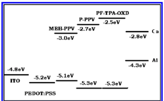
As depicted by the energy level diagram in Scheme 3, the energy level of the highest occupied molecular orbital (HOMO)
SCHEME 1: Chemical Structures of the Neutral Surfactants that Work as Effective Cathode Buffers and 1-Octadecanol as Well as Octadecane that Were Used as Contrasts
SCHEME 2: Chemical Structures of the Conjugated Polymers in Concern
of PEDOT:PSS is around -5.2 eV and the HOMO level of MEH-PPV is also around -5.1 eV. Therefore, there is almost no hole-injection barrier between PEDOT:PSS and MEH-PPV. On the other hand, the energy level of the lowest unoccupied molecular orbital (LUMO) of MEH-PPV is around -3.0 eV and the work functions of Al and Ca are -4.3 and -2.9 eV, respectively.30As a result, a large energy barrier for electron injection exists when Al is used as the cathode alone, while there is almost no barrier for the Ca cathode. Due to the difference on the electron injection, the external quantum efficiency at 35 mA/cm2differs tremendously between LEDs with Al as the cathode (less than 0.01%) and LEDs with Ca as the cathode (1.39%).
Table 1 presents the external quantum efficiency, driving voltage, and brightness of MEH-PPV-based LEDs with different kinds of cathode structures at a current density of around 35 mA/cm2. The maximum external quantum efficiency for each device is also listed for reference. The results show that, together with the Al cathode, the PEG-based neutral surfactant molecules (P6TE, P12TE, BJ76), PPG, as well as their copolymers (PEP and EPE) all demonstrate comparable device performances. It should be mentioned that the thickness of the neutral surfactant layer has not yet been optimized. Nevertheless, all of the external quantum efficiencies of these devices are more than 2 orders higher than that of the control device that uses only Al alone as the cathode without inserting such a kind of neutral surfactant layer. The performance of the devices reaches the same level or sometimes an even higher level than that of another control device with Ca as the cathode.
Since open-circuit voltages can reflect the built-in electric field strength, the barrier for electron injection in the case of the same anode structure in those devices can be measured.31 They were derived from the zero current points of the
photo-current-voltage characteristics under the illumination of a 100 mW/cm2AM1.5 simulated solar source. As expected from the work-function difference between Ca and Al, the LED with the Ca/Al cathode exhibits an open-circuit voltage (Voc) of 1.52 eV, much larger than that of the LED with the Al cathode, 1.26 eV. As shown in the last column of Table 1, by adding a layer of neutral surfactant, the open-circuit voltages of those devices were increased to the same level as the LED with Ca as the cathode, showing that the electron-injection barriers were reduced to a similar level when Ca was used as the cathode. In our previous publication, we made an elaborate comparison between devices with the structures ITO/PEDOT:PSS/MEH-PPV/P12TE/Al and ITO/MEH-ITO/PEDOT:PSS/MEH-PPV/P12TE/Al to understand the mechanism for this dramatic lowering of the electron-injection barrier. Because the HOMO level of PEDOT:PSS, -5.2 eV, is very close to the HOMO level of MEH-PPV, -5.1 eV, the contact between PEDOT:PSS and MEH-PPV is basically Ohmic. Together with the fact that hole transport is dominant in MEH-PPV,32an abundance of holes can be transported to the cathode side and be blocked at the MEH-PPV/P12TE interface. This hole accumulation can form increased local electric field intensity within the P12TE layer. It is this increased field intensity that greatly enhances the injection of electrons. For the latter device, it only has bare ITO without a PEDOT: PSS anode buffer layer. The work function of ITO is around -4.7 to -4.8 eV,33and a barrier of∼0.3 eV for hole injection to MEH-PPV exists. As a result of lacking abundant hole accumulation at the MEH-PPV/P12TE interface, the P12TE layer behaves as a pure insulating layer and the LED shows a performance even worse than that obtained when using Al alone as the cathode. On the basis of this sharp contrast, the greatly increased electron injection in LEDs with a configuration of ITO/PEDOT:PSS/MEH-PPV/P12TE/Al can be explained as follows: The abundant hole accumulation at the MEH-PPV/ P12TE interface forms a very strong local electric field within the P12TE layer. This enhanced electric field will increase the injection of electrons either via the increased tunnel efficiency34 or by lowering the electron-injection barrier to a similar level as when Ca is used as the cathode via the realignment of the dipole moment of the polar surfactant.35
To further elucidate the mechanism, we chose octadecane, a pure alkyl chain, and 1-octadecanol with one hydroxyl end group as model compounds for contrasts. As depicted in Table 1, inserting a layer of octadecane only has a small effect on the device performance, showing that the tunnel efficiency increase mechanism plays a very minor role on the electron injection. On the other hand, inserting a layer of 1-octadecanol, a polar molecule with the potential of realignment of polar moment, shows a much more prominent performance enhancement with the maximum external quantum efficiency reaching 0.677%. This shows that between the tunnel efficiency increase and
SCHEME 3: Demonstration of the Energy Levels of the Conjugated Polymers to the Work Functions of the ITO, Ca, and Al
TABLE 1: Performance of LEDs with Device Structure ITO/PEDOT:PSS/MEH-PPV/Cathode cathode J (mA/cm2) biasa (V) ηexta (%) Ba (cd/m2) ηmax (%) Voc (V) Al 35.1 3.69 0.0089 4.24 0.019 1.26 Ca/Al 34.7 3.63 1.39 493 1.90 1.52 P6TE/Al 35.1 3.72 1.74 985 2.14 1.54 P12TE/Al 34.2 3.50 1.70 900 2.33 1.56 BJ76/Al 34.9 4.09 1.85 928 2.21 1.42 PPG/Al 34.9 5.17 1.24 610 1.45 1.56 PEP/Al 34.8 4.57 1.08 571 1.35 1.52 EPE/Al 34.7 3.49 1.39 757 1.79 1.58 octadecanol/Al 35.4 4.31 0.258 178 0.677 1.37 octadecane/Al 35.6 4.75 0.047 21.3 0.053 1.16
aCorresponding to a current density of around 35 mA/cm2.
TABLE 2: Performance of LEDs with Device Structure ITO/PEDOT:PSS/EL Polymer/Cathode EL polymer cathode J (mA/cm2) biasa (V) ηexta (%) Ba (cd/m2) ηmax (%) Voc (V) MEH-PPV Al 35.1 3.69 0.0089 4.24 0.019 1.26 MEH-PPV Ca/Al 34.7 3.63 1.39 493 1.90 1.52 MEH-PPV EPE/Al 34.7 3.49 1.39 757 1.79 1.58 P-PPV Al 35.1 7.03 0.0416 43.7 0.046 1.27 P-PPV Ca/Al 35.1 6.01 1.41 1526 1.62 1.73 P-PPV EPE/Al 34.9 5.83 3.10 3130 3.21 1.97 PF-TPA-OXD Al 35.2 10.6 0.0369 12.9 0.053 1.55 PF-TPA-OXD Ca/Al 34.8 8.23 0.616 390 0.637 1.98 PF-TPA-OXD EPE/Al 34.9 6.79 0.579 219 0.704 2.11
dipole moment realignment mechanisms the latter plays a more dominant role.
However, even this mechanism cannot completely explain the contribution of performance enhancement when neutral surfactant is used as the cathode buffer layer because the performance of MEH-PPV-based LEDs with the 1-octadecanol/ Al cathode is 2-3 times lower than that of the LEDs with neutral surfactants as the cathode buffer layer. The main structure difference between the neutral surfactants and octa-decanol results from the lack of a periodical appearance of oxygen on the molecular chain of the latter. The mechanism proposed by Deng et al.22explains that the coordination between Al atoms (implanted into the surfactant layer during the cathode evaporation) and oxygen atoms in PEG (PPG and their copolymers also) may form an ultrathin layer of interfacial n-type MEH-PPV that contributes to the electron-injection barrier-lowering phenomenon. We believe this n-type doping
effect moves the recombination zone from the area very near the cathode to the inner area with less plasmon resonance quenching.36
Similar improvements were also observed in the LEDs with green and blue emissions that were fabricated on the basis of two series of light-emitting conjugated polymers, poly(phenylene vinylene) derivatives (PPVs) as well as polyfluorenes (PFs). The device performance parameters of them with three different cathode candidates, Al, Ca/Al, or neutral surfactant (EPE as an example)/Al, are collected in Table 2. External quantum efficiency versus current density characteristics and brightness versus current density characteristics of those devices are also compared in Figure 1 (MEH-PPV), Figure 2 (P-PPV), and Figure 3 (PF-TPA-OXD). When neutral surfactant was used as the cathode buffer layer together with Al, they all showed a much more improved performance than even the LEDs with Ca as the cathode. From the energy level diagram in Scheme 3, it is easy to judge that the mechanisms deduced from MEH-PPV-based LEDs would also apply to P-MEH-PPV-based and PF-TPA-OXD-based LEDs. In conjunction with this, photocurrent-voltage characteristics (Figure 4, with P-PPV-based LEDs as examples) and the open-circuit voltage variation presented in Table 2 give us quite clear evidence for this judgment.
Figure 1. External quantum efficiency vs current density characteristics and brightness vs current density characteristics of the LEDs based on MEH-PPV with different cathodes: Al (0); Ca/Al (O); EPE/Al (4).
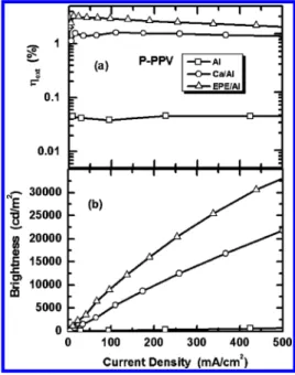
Figure 2. External quantum efficiency vs current density characteristics and brightness vs current density characteristics of the LEDs based on P-PPV with different cathodes: Al (0); Ca/Al (O); EPE/Al (4).
Figure 3. External quantum efficiency vs current density characteristics and brightness vs current density characteristics of the LEDs based on PF-TPA-OXD with different cathodes: Al (0); Ca/Al (O); EPE/Al (4).
Figure 4. Photocurrent density of the P-PPV-based LEDs with PEDOT:PSS as the anode buffer layer but different cathodes under the illumination of a simulated AM1.5 light source (100 mW/cm2).
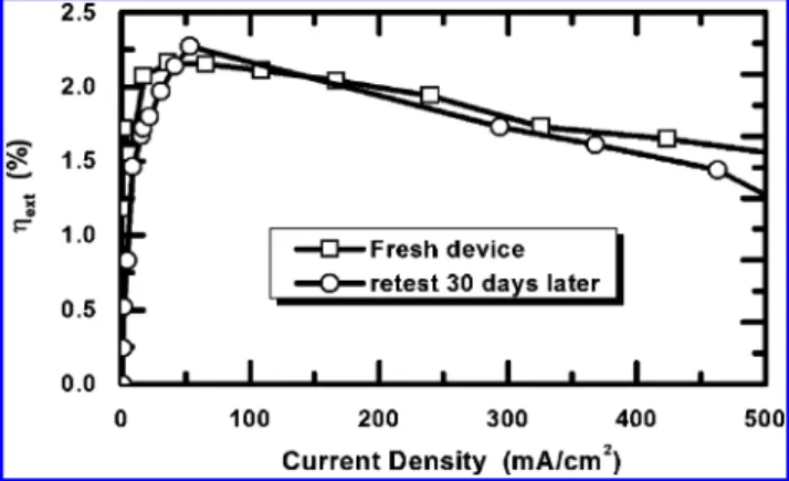
Because the number averaged molecular weights (Mn) of neutral surfactants, P6TE, P12TE, BJ76, PPG, and PEP inves-tigated up until now are in the range from about 500 to about 2000, a concern on their effect to the device stability might arise. In contrast to this, the Mnvalue of EPE is about 13 000. A very uniform solid-state thin film can be formed by EPE via spin coating. More importantly, the stability of LEDs with EPE/ Al as the cathode is very promising during shelf storage. As shown in Figure 5 with P-PPV as an example, the external quantum efficiencies of two neighboring LEDs on the same ITO substrate, with one being tested soon after the device fabrication and encapsulation and another being tested after shelf storage for 30 days, were almost the same, showing very good shelf stability.
Conclusions
In summary, high-efficiency polymer light-emitting diodes were fabricated by spin coating a layer of nonionic neutral surfactant between the EL layer and the high-work-function aluminum cathode. It was found that both the poly(ethylene glycol)-based and poly(propylene glycol)-based surfactants as well as their copolymers can all bring similar performance enhancements. Device performance comparable to or even better than that of control devices with a calcium cathode was achieved for both poly(p-phenylene)-based and polyfluorene-based con-jugated polymers with various emission colors. It was proposed and verified with confident experiments that when the combina-tion of neutral surfactant and aluminum was used as the cathode, the abundant hole injection through a hole-transporting layer (PEDOT:PSS as an example) and hole pile-up at the inner side of the EL/surfactant interface will cause an effective electric field to induce the realignment of the dipole moment of those polar surfactant molecules. The barrier to electron injection is lowered in this way. On the other hand, the coordination of an aluminum atom to the oxygen on the molecular chain of the surfactant may cause n-type doping to the EL polymer near the surfactant, thus contributing to enhancement of device perfor-mance via either increased electron injection or moving the recombination zone to the less quenching interior area of the EL layer.
Acknowledgment. Financial support by the Air Force Office
of Scientific Research (AFOSR) through the MURI Center and
the National Science Foundation through the NSF-STC Program are acknowledged. A.K.-Y.J. thanks the Boeing-Johnson Foun-dation for financial support. Y.-H.N. thanks Dr. Hong Ma for helpful discussion.
References and Notes
(1) Burroughes, J. H.; Bradley, D. D. C.; Brown, A. R.; Marks, R. N.; MacKay, K.; Friend, R. H.; Burn, P. L.; Holmes, A. B. Nature (London)
1990, 347, 539.
(2) D’Andrade, B. W.; Forrest, S. R. AdV. Mater. 2004, 16, 1585. (3) Braun, D.; Heeger, A. J. Appl. Phys. Lett. 1991, 58, 1982. (4) Cao, Y.; Yu, G.; Parker, I. D.; Heeger, A. J. J. Appl. Phys. 2000, 88, 3618.
(5) Gommans, H. H. P.; van der Gon, A. W. D.; Andersson, G. G.; van IJzensoorn, L. J.; Pijper, R. M. T.; Brongersma, H. H. J. Appl. Phys.
2003, 94, 5756.
(6) Nakamura, A.; Tada, T.; Mizukami, M.; Yagyu, S. Appl. Phys. Lett.
2004, 84, 130.
(7) Parker, I. D.; Cao Y.; Yang, C. Y. J. Appl. Phys. 1999, 85, 2441. (8) Hung, L. S.; Tang, C. W.; Mason, M. G. Appl. Phys. Lett. 1997, 70, 152.
(9) Piromeriun, P.; Oh, H.; Shen, Y.; Malliaras, G. G.; Scott, J. C.; Brock, P. J. Appl. Phys. Lett. 2000, 77, 2403.
(10) Yoon, I.; Kim, J.-J.; Lee, T.-W.; Park, O.-O. Appl. Phys. Lett. 2004, 76, 2152.
(11) Le, Q. T.; Yan, L.; Gao, Y.; Mason, M. G.; Giesen, D. J.; C. W. Tang, J. Appl. Phys. 2000, 87, 375.
(12) Shaheen, S. E.; Jabbour, G. E.; Morrell, M. M.; Kawabe, Y.; Kippelen, B.; Peyghambarian, N.; Nabor, M.-F.; Schlaf, R.; Mash, E. A.; Armstrong, N. R. J. Appl. Phys. 1998, 84, 2324.
(13) Hung, L. S.; Zhang, R. Q.; He, P.; Mason, G. J. Phys. D 2002, 35, 103.
(14) Heil, H.; Steiger, J.; Karg, S.; Gastel, M.; Ortner, H.; von Seggern, H.; Sto¨βel, M. J. Appl. Phys. 2001, 89, 420.
(15) Brown, T. M.; Friend, R. H.; Millard, I. S.; Lacey, D. J.; Burroughes, J. H.; Cacialli, F. Appl. Phys. Lett. 2004, 77, 3096.
(16) Campbell, I. H.; Kress, J. D.; Martin, R. L.; Smith, D. L.; Barashkov, N. N.; Ferraris, J. P. Appl. Phys. Lett. 1997, 71, 3528.
(17) Xu, Q.; Ouyang, J.; Yang, Y. Appl. Phys. Lett. 2003, 83, 4695. (18) Lee, T.-W.; Park, O. O.; Do, L.-M.; Zyung, T.; Ahn, T.; Shim, H.-K. J. Appl. Phys. 2001, 90, 2128.
(19) Cao, Y.; Yu, G.; Heeger, A. J. AdV. Mater. 1998, 10, 917. (20) Lee, T.-W.; Park, O. O. AdV. Mater. 2001, 13, 1274.
(21) Lee, T.-W.; Lee, H.-C.; Park, O. O. Appl. Phys. Lett. 2002, 81, 214.
(22) Deng, X. Y.; Lau, W. M.; Wong, K. Y.; Low, K. H.; Chow, H. F.; Cao, Y. Appl. Phys. Lett. 2004, 84, 3522.
(23) Niu, Y.-H.; Ma, H.; Xu, Q.; Jen, A. K.-Y. Appl. Phys. Lett. 2005, 86, 083504.
(24) Braun, D.; Heeger, A. J. Appl. Phys. Lett. 1991, 58, 1982. (25) Spreitzer, H.; Becker, H.; Kluge, E.; Kreuder, W.; Schenk, H.; Demandt, R.; Schoo, H. AdV. Mater. 1998, 10, 1340.
(26) Johansson, D. M.; Srdanov, G.; Yu, G.; Theander, M.; Ingana˜s, O.; Andersson, M. R. Macromolecules 2000, 33, 2525.
(27) Shu, C.-F.; Dodda, R.; Wu, F.-I.; Liu, M. S.; Jen, A. K.-Y. Macromolecules 2003, 36, 6698.
(28) Greenham, N. C.; Friend, R. H.; Bradley, D. D. C. AdV. Mater.
1994, 6, 251.
(29) Forrest, S. R.; Bradley, D. D. C.; Thompson, M. E. AdV. Mater.
2003, 15, 1043.
(30) Weast R. C.; Astle, M. J. CRC Handbook of Chemistry and Physics, 63rd ed.; CRC Press: Boca Raton, FL, 1982.
(31) Wei, X.; Raikh, M.; Vardeny, Z. V.; Yang, Y.; Moses, D. Phys. ReV. B 1994, 49, 17480.
(32) Campbell, I. H.; Smith, D. L.; Neef, C. J.; Ferraris, J. P. Appl. Phys. Lett. 1999, 74, 2809.
(33) de Morais, T. D.; Chaput, F.; Lahlil, K.; Boilot, J.-P. AdV. Mater.
1999, 11, 107.
(34) Parker, I. D. J. Appl. Phys. 1994, 75, 1656.
(35) Sigaud, P.; Chazalviel, J.-N.; Ozanam, F. J. Appl. Phys. 2002, 92, 992.
(36) Chance, R. R.; Prock, A.; Silbey, R. In AdVances in Chemical Physics; Prigogine, I., Rice, S. A., Eds.; Wiley: New York, 1978; pp 1-65.
Figure 5. External quantum efficiency vs current density characteristics from a freshly made LED (0) and from the same device that was stored on a shelf for 30 days (O). Device structure: ITO/PEDOT:PSS/P-PPV/ EPE/Al.