2006IEEEInternational Conferenceon Systems, Man,andCybernetics
October
8-11, 2006,
Taipei, TaiwanDesign and
Implementation
of the Intelligent Stop and Go System in
Smart Car, TAIWAN iTS-1
Bing-Fei Wu, Senior Member, IEEE, Tsen-Wei Chang, Jau-Woei Perng, Member, IEEE, Hsin-Han
Chiang,
Student Member,
IEEE, Chao-Jung Chen, Student Member, IEEE, Tien-Yu Liao, Shinq-JenWu,Member,
IEEE,and Tsu-Tian
Lee,Fellow,
IEEEAbstract-Inthis paper, the intelligent Stop and Go system
(S&G) is designed and implemented for low speed traveling vehicles in urbane area. The human-driving like fuzzy logic
control is applied for achieving desired speed and safe inter-vehicle spacing. By proposed intelligent Stop and Go system, the following functions can be obtained including
collision avoidance, traffic accidence reduction, driving
pressure decrease, and increment of traffic capability.
Furthermore, the real car equipped with sensors and a
longitudinal controller is provided to demonstrate three
scenariosthat meetthesituations of lowspeedvehicles inurban area. Threeseniors includepedestrian crossing,stopin front of
obstacle, and Stop and Go. The application of proposed intelligent StopandGo system ispossiblefor lowspeed driving
assistance in urban area by ourexperimentalresults.
I. INTRODUCTION
T he main objective of the intelligent transportation system(ITS)istointegrateman,vehicle, and information of roadway for providing a safe environmentoftransportation and solving practical traffic problems. In the researches of intelligent vehicle, how to applytechnologies ofelectronic, information, machine andsensorin ITShas becameapopular subject for mobile industries and academic organizations. One of ITS technologies is how to increase the traffic capability by intelligent vehicle. In highway, the speed of vehicles locates in 40 km/hto 170km/h and the preceding vehicleskeeptraveling. Therefore,theadaptive cruise control (ACC) isapopular methodforincreasingcapabilityoftraffic. On the contrary, in urban area, the speed ofvehicles is less than 40 km/h and the preceding vehicles stop and go frequently. The intensive attention causesthe sufferance of driver's
sprit,
andeven more, leadstotraffic accidents. Itis driver'snightmares. Furthermore, in this situation, the traffic capability is reduced and much time is spent for drivers. Therefore, the StopandGo(S&G)isdevelopedtodeal with theseproblems. Ourworkis todesignanintelligentstopand go system (ISGS) for solving previous mentioned problems andis verified inarealcar.Recently,theresearchesofS&Gbasicallycanbeclassified into four fields including human driving comfortable consideration, robust control, intelligent control, andothers.
B.F.Wu*,T. W.Chang,J.W.Perng,H. H.Chiang, C. J.Chen,and T. Y. LiaoarewithDepartment ofElectricalandControl Engineering, National ChiaoTung Univeristy,Hsinchu,300,Taiwan,(phone:886-3-5131538; fax: 886-3-5712385;*conespondingauthore-mail:[email protected]).
S. J. Wu is with the Department ofElectrical Engineering, Da-Yeh
Uniniversity,ChanghuaCity, 515, Taiwan,(e-mail:jen(&mail.dyu.edu.tw).
T.T.Leeis withDepartment ofElectricalEngineering, NationalTaipei
In human driving comfortable consideration [ 1-4], the researches consider how to generate the proper reference signal for controller to let driver feel comfort by LQ, statistical analysis, least square method, and least-squared withforgetting factor respectivepapers. By theseapproaches, the design of controller will be simpler than incorporating comfortable consideration into controller. About robust control, [5] uses the second order sliding mode control to implement the stop and go system in a real car. The model match control (MMC) based on sliding mode control is applied into S&Gin [6]. The MMC based on sliding mode control is more robust andrapidresponse than MMC based onconventionalPIDcontroller. Inintelligent field,the fuzzy logic controller is applied into electronic vehicle control rather thanconventional vehiclein [7]. The other researches including, study in S&G longitudinal vehicle model and vision-based S&G for longitudinal and lateral are addressed in [8]and[9],respectively.
Our work achieves the characteristics of safety, humanization and efficiency in ITS. In the following, the functions ofourworkare providedto satisfythreekinds of characteristics. The functions ofour work contain collision avoidance, traffic accidence reduction, scanning deadspace elimination of radar, driving pressure decrease, controller with intelligent human-like driving behavior consideration, and increment oftraffic capability. Finally, three scenarios includingpedestriancrossing,stopin frontof anobstacle, and S&Garedemonstrated.
The paper isorganizedasfollows. In Section
II,
theoverall structure of ISGS is specified. The experimental results includingthreescenariosareexhibitedinSectionIII. Finally, theconclusionsaregiveninSectionIV.II. INTELLIGENT STOPANDGoSYSTEM
In this section, the overall design structure of ISGS and, longitudinal modelof S&Gareintroduced.
A. The OverallStructureofanIntelligentStopandGo System
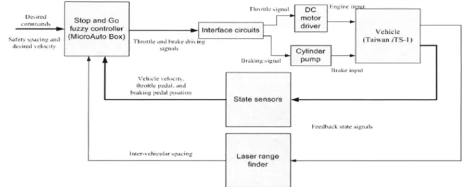
The overalldesignstructureisshowninFig. 1.Thevehicle sensors, including laser range finder for distance measurement, velocitysensor, and sensors ofbraking pedal and throttle angle position areadopted. The measuredstates
are transferred into fuzzylogic controller, which commands the vehicle to follow a given speed and safety spacing by throttle andbraking systems. Inthe case of an existing front obstacle, the vehicle will stop completely with safety distance. When the obstacle vanishes, the vehicle will go forwardaspresetvelocity.
Fig. I Theoverallstructure of ISGS
B. LongitudinalModel ofStopandGo
[7],[8]
Basically, longitudinal vehicle dynamic is complex and nonlinear. It contains engine and transmission systems, brakesystem,and drive train system as shown inFig. 2.The real car, TAIWAN, iTS-1 provided by China Motor Corporation, is shown inFig.3. Therelative parameters of real car arelistedin Table 1. Assumptions of no torsion of drivingaxleandslipatthe wheelareconsideredforsimplify of longitudinal S&G vehicle model [8]. The distinct components oflongitudinal vehicle model of S&G can be listedasfollowing[7].
1) I/O of Engine andtransmissionsystems
- Input:Throttleangle (i.e. Engine input) - Output:Drivingenginetorque
- Output(enginetorque)dependenton
* Engine input
* Gearratioof transmission system * Vehicle speed and wheelspeed
- Gearratioisanonlinearfunction of the
engine input 2) I/Oof Brake system
- Input: Brakeinput - Output:Brakingtorque
- Brakingtorqueisanonlinearfunction of
brakingpressure 3) I/OofDrivetrain
- Input:Driving enginetorqueandbraking
torque
- Output: vehiclespeed/acceleration - Drivetrain iseffectedby wheel inertia and
externaldisturbance(aerodynamic drag, rollingresistance, and climbing torque) The more detail mathematical descriptionsoflongitudinal S&Gvehicle modelcanbe referred in[8].
Due tothenonlinearity ofvehicle model, uncertainty of vehicle parameters and external disturbances from aerodynamicsand roadcondition, thefuzzylogic isabetter choice for controllerdesign.
AFig.2Lrogunlecs RladmdloSG 7
Fig.2Longitudinalvehicle model of S&G[7]
TABLE I
THERELATIVE PARAMETERS OF TAIWAN iTS-1 MISUBISHI SAVRIN 2.4
Engine type L4DOHC 16VVVT+DDM
Exhaust 2400 c.c.
Horsepower(hp/rpm) 150/6250
Torsion
(kgm/rpm)
19.2/3000Transmission
INVECS-II
SPORT-MODE4A/T
III. INTELLIGENTFuzzY LOGIC CONTROLLER
Inourdesignasshown in Fig. 4, the fuzzy logic controller
is adopted, because accurate mathematical model and imprecise inputs are not needed. Moreover, it can handle
nonlinearity and uncertainty rather than conventional nonlinear controller. Finally, the linguistic control laws are
like the driving behavior of human being.Inourdesign,two fuzzy logic controllers for throttle and brake systems are
applied to achieve desired commands including safety distance ( Dd ) and desired velocity ( vd ). The PID (KPB,K1B, and KDB) and PD (KPT and KDT) gains are
tuned properly for imitating human driving behavior. The membership functions and rule tables of fuzzy logic controllers for throttle and brakesystemsare shown in Figs.
5 and 6, respectively. The switching mechanism bases on
whether D Dd is ornot. D is the inter distance measured
by laserrangefinder. IfD Dd,thebrakingdriving signal is
enable. On the other hand, ifD<Dd, the throttle driving
signal is enable.
Fig.4The Structure ofintelligent fuzzy logic controller
NB NS ZR PS PB
(c) The rule table for fuzzy logic of throttle control Fig. 5 Membership functions and rule table for throttlesystem
NB NS LR PS
/~~~~~~~~~
P'B
-8 3 0 3 8 edt
(a) The membership functions for fuzzy logic input edt
Ldtd
(b) The membership functions for fuzzy logic input edid
rnf I nif2 tnmf3 af4 tmf5
4rd
(a)The membershipfunctions for fuzzy logic input ev,
NB NS PS PB
(c) The membership functions for fuzzy logicoutputUbrake
t1dtds NiB NS ZR PS PB
NH
1 lifI nlfl il!fI Intl rl NS mf nil tl[ i n!1
rzm4 mW mn14 m4 rml
P11 ntl miS mi'5 Ins mtf5
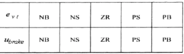
(d)The ruletableforfuzzylogicofbrakecontrol Fig.6Themembership functions and rule table for brake system
0
0
-l -(.7 0 0.7 1
(b)Themembershipfunctions forfuzzy logicoutput Uthrotlle
It I
II
l1
IV. EXPERIMENT RESULTS
Inthissection,theequipments in TAIWAN iTS-1 will be describedfirst.Threekinds of scenariosarearranged to meet the traffic situations in urban area. The results show that proposed ISGS can be applied into real application.
A. Vehicle Equipments
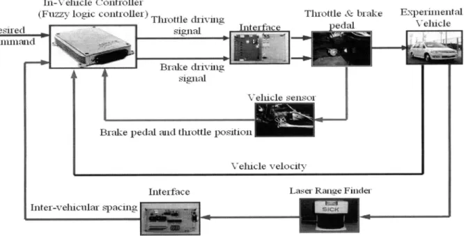
Theequipments in TAIWAN iTS- 1 as shown in Fig. 7 can be describedasfollowing:
1) In-Vehicle Controller: The intelligent fuzzy logic is implemented inreal-time hardware MicroAutoBox to generate throttle and brake driving commands for achieving desired signals.
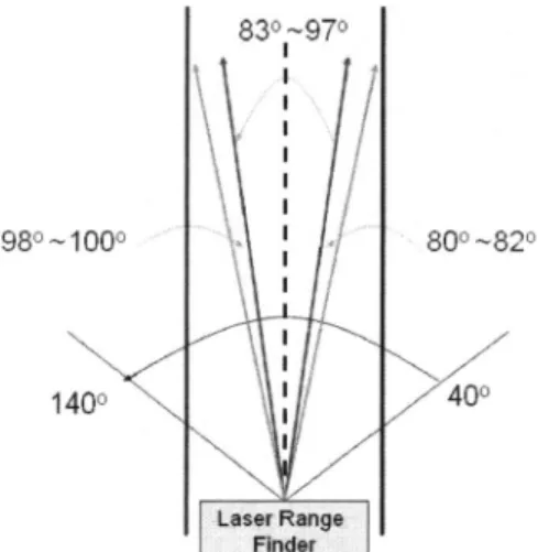
2) Sensors: The laser rangefinderisprovidedto measure
inter-vehicle distance and designed to eliminate the deadspace ofscan for safetyas shown inFig. 8. The total scanangle ofradaris 100°(40° 140°). The scan
angle
83° 970oflaser range finder ischosentodetectthe distance with respect to preceding vehicle. The additional 3°inboth sidesare usedtodetect obstacles for reducing the dead space ofscan. The velocity is measured from appearance of vehicle speed. The positions of throttle angle and braking pedal are
measured by throttle and brake position sensors
respectively.
3) Braking System: The cylinder pump mechanism is used to force the
braking pedal
to achieve proper action.4)ThrottleSystem:TheDCmotorcontrolledbyPWMis appliedtocontrol the
angle
ofthrottle.5) PowerSystem: The power system
including
inverters and two batteries isprovided
forMicroAutoBox,
computer,andinterface circuits.
6) PC: The PC is
provided
for recoding all data from in-vehiclesensors.II-N
elncle
(Cnlltrioller
(<Fls-lt3ic-lltv:Ll;)Tlixcttle
&hiviiig
Desireda1
si--''4B. Experimental Scenarios
The experiment with TAIWAN iTS-1 is held at a public parking lot. In the following, three scenarios are demonstratedforverifying the feasibility of our ISGS. 1)Scenario 1: Pedestrian crossing (velocityl 5 km/h, safety
distance 4mand automaticstart-up)
In this scenario, the real car approaches at 15 km/h, then the pedestrian in front of vehicle 15m is detected. This information is sent to the controller, and the cylinder pump mechanism is acted to brake real car before the pedestrian 4m. Afterpedestriancrossesthe road,the real car will go forward continuously as set velocity 15 km/h. The relative experimentaldatais shownin Fig. 9.
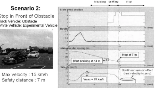
2)Scenario 2: Stop in front of an obstacle (velocity 15 km/h andsafe distance 7m)
In the following, an obstacle appears in front of vehicle, and thevehiclewill enable brake before 14mof thisobstacle. Thevehicle will stopbeforethe safetydistance 7m. Fig. 10 showsthe relative experimentaldata.
3)Scenario3: Stop &Go(star-updistance5mand safe distance3m)
Due to the traffic jam getting worse day by day, in this scenario, the situation of traffic jam is considered. In this situation, all vehicles stop and go by front vehicles in 0-5 km/h onebyoneslowly. TheISGS isdesignedforreducing driverspiritual loads.
In this scenario, by the distance and velocity of front vehicle measured with laser range finder, the fuzzy logic controller will control throttle and brake to follow front vehicles.
FromFig.
11,
when the interdistance islargerthanSm,
the experimental vehicle will follow up and stop before front vehicle23m. Therefore, theintelligentstop and go systems will reduce the spiritual load and increase the traffic capability.Throttle&- bhrak-e Experneittal
ped,a Velicle
_ ~ ~~~~~~~
Bi-ake pedal iuiclthrottle posltioll
-^
Lasel
Rati2Le Fiierte
980 ..1000 140 800-~820 7 7', 7'
/4Q01
~Lase:r
Range FinderFig.8Dead space eliminationapproachoflaser rangefinderscan
V. CONCLUSION
By
ourdeveloped
technology
and testedonrealroads,
theapplication
ofintelligent
stop and go can be utilized toimprove
the traffic situation. Three scenariosincluding
pedestrian crossing,
stopin front ofanobstacle,
andstop& go have been demonstrated on the real road forverifying
thefeasibility
of theproposed
ISGS.AcKNoWLEDGMENT
Thework is
supported by Promoting
Academic Excellence ofUniversities fromMinistry
ofEducation,
Taiwan,
R.OC. underGrant No. EX-91I-E-FA06-4-4.Theauthorswouldalso like tothankProf. C. K. Lin forthe constructivesuggestion
on
equipping cylinder
pump mechanism inbraking
systems
and C. H.
Yen,
C. H.Lee,
and L. S. Ma for their devotion in datacollectionandexperimental
demonstration.Scenario 1:
Pedestrian Crossing
REFERENCES
[1] K.Yi,I.Moonand Y. D.Kwon,"Avehicle-to-vehicle distance control
algorithm for stop-and-go cruise control," in 2001 Proc. ofIEEE
Intelligent Transportation SystemsConf,pp. 478-482.
[2] M. Canale, and S. Malan, "Tuning ofStop and Go driver control
strategies using drivingbehavioranalysis,"in 2002 Proc.ofIntelligent
VehicleSymposium,pp.407-412.
[3] M. Persson, F. Botling,E. Hesslow, and R. Johansson,"Stop & Go
controllcrforadaptivccruisccontrol,"in 1999Proc.ofIEEEmnt.Conf.
ControlApplications,pp. 1692-1697.
[4] K. Yi, and I. Moon, "A driver-adaptive stop-and-go cruise control
strategy,"in 2004 Proc.ofIEEE Int.ConfonNetworking, Sensingand
Control,pp. 601-606.
[5] L. Nouveli&re and S. Mammar, "Experimental vehicle longitudinal
controlusingsecond orderslidingmodes,"in 2003 Proc.ofAmerican ControlConf.,pp.4705-4710.
[6] Y. Bin, K. Li, X. Lian, H. Ukawa, M. Handa, and H. Idonuma, "Longitudinalaccelerationtracking control of vehicularStop-and-Go
cruise control systems," in 2004 Proc. of IEEE Int. Conf on
Networking, SensingandControl,pp.607-6 12.
[7] Z. Eizad, and L. Vlacic,"A controlalgorithmandvehicle model for
Stop& Gocruisecontrol."in 2004 Proc.ofIEEEIntelligent Vehicles
Symposium,pp. 401-406.
[8 H.Ohtsuka and L.Vlacic,"Stop& Govehiclelongitudinal model,"in
202Proc.ofIEEE5hInt.ConfonIntelligent Transportation Systems,
pp. 206-209.
[9] M.Parent,P.Daviet,J.-C.Denis,and T.M'Saada,"Automaticdriving
in Stop and Go Traffic," in 1994 Proc. of Intelligent Vehicles
Symposium,pp. 183 188.
Pedestrian acceleration, brad'ing crossing9restart
Stopat4m
SatbrakingatI5
Nnliinearsensoreffect
freaIeocityis eroI
Vmax'~15kmtII
Max velocity: 15 km/h
Safety distance: 4 m
Automatic start-up
Fig.9Stopbefore thepedestrianinScenario I
vwoing braking stclp
Scenario 2:
Stop in Front of Obstacle
BlackVehicle: Obstacle
WhiteVehicle: ExperimentalVehicle
Max
velocity:15
km/h
Safety
distance
:
7 m
Fig.
Scenario:
Stop and Go
.10Stop in front ofobstacle in Scenario 2
IStgaitfunctiopn stp gn o go
o so o "q '90