Pulse Electrodepositions of PtRu on Large-Area Carbon
Nanotubes for Enhancement of Methanol Electro-Oxidation
Yi-Fan Hsieh,
*
Yu-Chi Hsieh,*
Pu-Wei Wu,**
,zChen-Hong Liao,*
andYun-Min Chang
*
Department of Materials Science and Engineering, National Chiao Tung University, Hsin-chu 300, Taiwan We employed an electroless deposition technique to prepare Ni seeds uniformly on a carbon cloth, followed by carbon nanotube 共CNT兲 formation at an elevated temperature. Subsequently, a pulse electrodeposition was used to impregnate PtRu nanoparticles on the CNT structure. Similar procedures were performed on carbon supports including Vulcan XC72R, BP2000, and carbon nanocapsules共CNCs兲 for comparison purposes. Diffraction patterns from an X-ray confirmed a PtRu alloyed phase. An analysis from inductively coupled plasma-mass spectrometry indicated that the PtRu composition was relatively unchanged. Images from scanning and transmission electron microscopes revealed dense CNTs throughout the carbon cloth with nanoparticulate PtRu evenly impregnated. Considerable PtRu aggregations were found on the CNCs and BP2000. We observed a significantly improved coulomb efficiency and an electrochemically active surface area for the CNT-grown carbon cloth. In both apparent current density and mass activity for methanol electro-oxidation, the CNT-grown carbon cloth revealed the largest values. We attribute the performance enhancement to the large-area CNT structure that allowed facile access of electrolytes.
© 2009 The Electrochemical Society. 关DOI: 10.1149/1.3246002兴 All rights reserved.
Manuscript submitted March 16, 2009; revised manuscript received September 14, 2009. Published November 10, 2009.
The development of direct methanol fuel cells共DMFCs兲 has re-cently received considerable attention for their potential applications in transportation and portable electronics.1,2Due to the CO poison-ing in methanol dehydrogenation, electrocatalysts such as PtRu are used to improve the DMFCs efficiency.3,4Responsible mechanisms for methanol electro-oxidation, including bifunctional model and ligand effect, are proposed.5,6 The bifunctional model involves a synergistic mechanism in which a partially oxidized surface Ru pro-vides the oxygenated species to oxidize the poisoning intermediates to CO2. The ligand effect describes the alteration of the electronic
structure in Pt caused by nearby Ru atoms. Instead of directly de-posited on an electrode structure, the PtRus are prepared as nano-particles and impregnated on carbonaceous materials to obtain better distribution, size, and utilization rate. The conventional selection criteria for carbon supports are large surface area, reasonable elec-trical conductivity, and acceptable corrosion resistance.
Many types of carbonaceous materials are investigated as elec-trocatalyst supports.7 For instance, extensive reports cover carbon blacks, mesoporous carbons, and nanostructured carbons with im-pressive results.8-13In particular, the nanostructured carbons demon-strate promising characteristics because their unique morphologies and shapes often lead to synergistic effects when electrocatalysts are deposited. To date, a wide variety of nanostructured carbons, such as carbon nanotubes共CNTs兲, carbon nanocapsules 共CNCs兲, and carbon nanofibers, have been synthesized and evaluated for DMFCs.14-18 Among them, CNTs have been investigated extensively as catalyst supports for DMFCs and polymer electrolyte fuel cells for both anodes and cathodes.19-24It is recognized that the CNTs demonstrate superb characteristics over conventional carbon blacks in surface structure, mechanical and thermal properties, electrical conductivity, and surface area. Moreover, due to their filamentous morphology, electrodes made of CNTs reveal a desirable porosity for facile ac-cess of electrolyte and gaseous reactants.16
Typical fabrication schemes for the CNT-based DMFC elec-trodes involve preparations of PtRu nanoparticles on the CNTs via a chemical route, followed by a physical transfer to a carbon cloth.25 Because the transfer process deposits the catalyzed-CNTs exclu-sively on the carbon cloth surface, the resulting catalyst utilization rate is rather limited.26To obtain better catalyst efficiency, an alter-native approach is to synthesize the CNTs directly on the carbon cloth, followed by electrodepositions of PtRu on the CNTs. This method is expected to produce significant improvements if the CNTs
could be distributed uniformly throughout the carbon cloth. One embodiment of this method was demonstrated recently by Tsai et al., in which an evaporation method was employed to prepare Ni nuclei for CNT growth, followed by a potentiostatic deposition to grow PtRu on the CNTs.27However, we realize that because of a possible shadowing effect in the evaporation step, the CNTs were grown preferentially on the exterior surface of the carbon cloth. Therefore, further enhancement is likely if the CNTs seeding could be im-planted underneath the carbon cloth.
In this work, we adopted an electroless deposition technique to prepare the Ni seeds uniformly throughout the carbon cloth, fol-lowed by CNT formation at an elevated temperature. Subsequently, a galvanostatic pulse deposition was conducted to deposit PtRu on the CNT-grown carbon cloth. Materials and electrochemical charac-terizations were carried out for methanol electro-oxidation studies.
Experimental
The CNTs were formed on a Teflon-free type-A carbon cloth from E-TEK pretreated by an electroless deposition of Ni as the catalytic seeds. First, the carbon cloth共2 ⫻ 6 cm兲 was washed in 5 M HNO3for 30 min at 60°C to render a hydrophilic surface. Next,
in a sensitization step, the carbon cloth was immersed in a solution containing 0.3 wt % SnCl2and 2.5 wt % HCl for 5 min to ensure adequate adsorption of Sn2+. Afterward, the sample was dipped into an activation solution containing 0.1 wt % PdCl2and 1 wt % HCl
for 3 min, allowing spontaneous oxidation of Sn2+to Sn4+and
re-duction of Pd2+to Pd to take place. Then, the activated carbon cloth
was submerged in a Ni plating bath共approximately pH 6兲 consisting of NiSO4共20 g/L兲 and NaH2PO2共27 g/L兲 at 75°C for 30 s. Upon
completion, the sample was thoroughly rinsed with deionized water and alcohol and dried for 10 min.
Before the formation of CNTs, the Ni-decorated carbon cloth underwent a reduction treatment at 600°C for 10 min in mixed gases of H2and Ar. Subsequently, C2H4 was introduced for another 12 min for CNT synthesis. The flow rates for Ar, H2, and C2H4were 450, 50, and 25 mL/min, respectively. After the CNT formation, the net weight increment was 20 mg/cm2. To deposit the PtRu nanopar-ticles by pulse electrodeposition, the CNT-grown carbon cloth was cut into three pieces 2⫻ 2 cm each and was inserted into a home-made sample holder that exhibited a circular opening of 1 cm2
ex-posed to the electrolyte. Next, the sample was immersed in a 0.5 M H2SO4 solution for 5 min to prepare a hydrophilic surface. The
galvanostatic pulse deposition of PtRu was performed by BaSyTec at 26°C with a plating bath including H2PtCl6共99.9 wt %兲, RuCl3
共99.9 w t%兲, NaNO2共97 wt %兲, and H2SO4共97 wt %兲. Their
con-centrations were 0.005, 0.005, 0.05, and 0.25 M, respectively. The
*Electrochemical Society Student Member.
**Electrochemical Society Active Member. z
E-mail: [email protected]
parameters employed were current on time共Ton, 50 ms兲, current
density 共50 mA/cm2兲, current off time 共T
off, 100 ms兲, and total
coulomb charge共8 C兲. A Pt foil 共10 cm2兲 was used as the counter electrode, and the distance between the working and counter elec-trodes was 3.5 cm. The current density and coulomb charge were based on the geometric area of the working electrode exposed to the electrolyte共1 cm2兲.
Electrochemical characterizations were carried out under N2
at-mosphere at 26°C using a Solartron SI 1287 potentiostat. A three-electrode arrangement was adopted where the Pt foil共10 cm2兲 and the Ag/AgCl were used as the counter and reference electrodes, respectively. The area for the working electrode was the geometric area exposed to the electrolyte共1 cm2兲. To determine the
electro-chemically active surface area 共ESA兲, cyclic voltammetric 共CV兲 scans in 0.5 M H2SO4were conducted for −0.2 to 0.7 V at 20 mV/s. For methanol electro-oxidation, the cyclic voltammetries were per-formed in a mixed solution of 0.5 M H2SO4and 1 M CH3OH for −0.2 to 0.9 V at 20 mV/s.
X-ray diffraction共XRD; Siemens D5000兲 with a K␣ of 1.54 Å was used to identify the relevant phase of the PtRu nanoparticles. A transmission electron microscope 共TEM; Philips Tecnai-20兲 was adopted to observe their morphologies and distributions on carbon supports. The loadings and molar ratios for the PtRu nanoparticles were determined by inductively coupled plasma-mass spectrometry 共ICP-MS; SCIEX ELAN 5000兲. The surface area of the CNTs was obtained by careful removal of the deposits from the carbon cloth and was analyzed using the Brunauer, Emmett, and Teller method 共BET兲 共Micromeritics Tristar 3000兲. The electrical resistivity of the CNT-grown carbon cloth was measured by a four-point probe 共Kei-thley 2000兲.
For comparison purposes, identical PtRu electrodepositions and electrochemical analysis were performed on carbon cloths precoated with Vulcan XC72R共XC72R兲, BP2000, and CNCs. The preparation method entailed an ultrasonic mixing of 5 mg Nafion and 5 mL C2H5OH for 30 min, followed by the addition of 8 mg of carbons
for another ultrasonication of 60 min. The carbon dispersion was then brush-painted on the carbon cloth共2 ⫻ 2 cm兲 with a resulting carbon loading in 2 mg/cm2.
Results and Discussion
Electroless Ni deposition plays a critical role over subsequent CNT synthesis because the growth of CNTs is influenced greatly by the distribution and the size of the Ni seeds. From our observations, excess Ni seeds engendered overgrowths of CNTs that resulted in structural instability. Inadequate Ni seeds produced insufficient CNT coverage. After repeated tries, we determined the optimized param-eters to prepare a suitable amount of Ni on the carbon cloth. The resulting Ni seeds contained 5 wt % of P. The 5 wt % of P was a codeposit from the electroless Ni bath because the NaH2PO2 was used as the reducing agent.
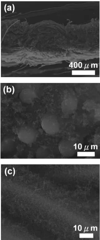
Figure1demonstrates the scanning electron microscope共SEM兲 images of the CNT-grown carbon cloth with selective areas enlarged for better contrast. As shown in Fig.1a, the thickness for the sample became 500–600 m, which was increased from the untreated car-bon cloth of 350 m. The structure was mostly intact with interwo-ven carbon fibers clearly visible. Figure1b and cexhibits the for-mation of CNTs on the interior area. The CNTs were grown in large areas on the carbon fibers with adequate spaces in between. The diameter for the untreated carbon fiber was 10 m. After CNT for-mation, its diameter increased significantly. According to Reshet-enko et al.,16this filamentous morphology is conductive to electro-lyte access that we believe could lead to better PtRu deposition.
To fairly evaluate the prospects of CNT as a catalyst support, we selected the XC72R, CNCs, and BP 2000 for PtRu electrodeposi-tions. The XC72R and BP2000 are often used as the electrode ma-terials with established properties.28,29The CNCs, synthesized by a flame combustion method, have demonstrated notable potentials.30-32TableIprovides the results from material
character-izations on the carbon supports under study. The CNTs revealed a surface area of 508 m2/g, which was larger than those of XC72R
and CNCs. In electrical resistivity, coating of carbon supports pro-duced a repro-duced value compared to the untreated carbon cloth.
Figure2presents the XRD patterns for the PtRu nanoparticles deposited on carbon cloths coated with XC72R, CNCs, BP2000, and CNTs, respectively. Due to interference from the carbon cloth and carbon supports, moderate noises in diffraction signals were evident. However, there existed several diffraction peaks, and their respon-sible planes were labeled accordingly. The signals from those of Pt revealed a face-centered cubic phase, with the peak positions slightly shifted to larger angles. This indicates that the Ru was al-loyed in the Pt lattice because a smaller Ru atom leads to the
reduc-Figure 1. SEM images for the CNT-grown carbon cloth in 共a兲
tion of the Pt lattice. The size of the PtRu nanoparticles could be estimated by Scherrer’s equation. Using the Pt共111兲 signals, their sizes were between 4 and 7 nm.
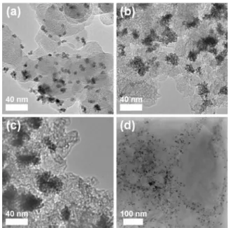
The TEM pictures for the PtRu nanoparticles on various carbon supports are exhibited in Fig.3. These images were also analyzed to determine the average PtRu sizes共listed in Table I兲. We obtained
uniform distributions of PtRu on XC72R and CNTs. In contrast, considerable aggregations were observed on the CNCs and BP2000. Because the CNCs and BP2000 consisted of relatively small carbon particles, we surmise that during electrodeposition, electrolyte trans-port into the micropores between these carbon particles was possibly interrupted. As a result, the formation of PtRu was confined on selective surface areas with electrolyte access. Electrolyte transport in XC72R and CNTs were not expected to be an issue because their sizes were larger, which allowed facile replenishments of Pt and Ru cations.
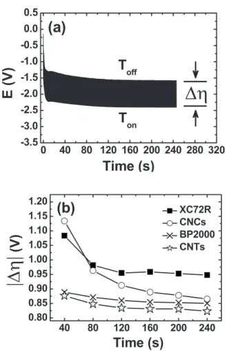
More details on the PtRu growth in various carbon supports can be obtained by analyzing their potential variations during galvano-static pulse depositions. Figure4adisplays a representative potential profile of CNTs for both Ton and Toff. Apparently, both potential values exhibited a slow decline initially and became stabilized after 160 s. Potential reading at Tonrepresented the deposition voltage
required for the PtRu nucleation and growth. In contrast, the poten-tial value at Toff indicated the open-circuit voltage reflecting the
surface state of the sample. Because the potential values fluctuated between Tonand Toff, we believe that their difference 共⌬兲 is the indicator for the overpotential during PtRu depositions. Therefore, a desirable carbon support is expected to reveal a smaller overpoten-tial and a larger coulomb efficiency. In Fig.4b, we provide overpo-tential variations共⌬兲 in the CNTs and carbon supports of XC72R, CNCs, and BP2000. Clearly, the CNTs demonstrated the smallest ⌬, while the XC72R exhibited the largest one. This suggested that the PtRu nanoparticles were relatively easier to form on the CNT-grown carbon cloth.
Variations in the PtRu molar ratios and coulomb efficiencies are shown in Fig.5. The compositions for the PtRu nanoparticles were rather consistent, with the Pt ratio varied between 82 and 77 atom %. Pt enrichments in the PtRu were commonly encountered during electrodepositions because the redox potential of Pt was more posi-tive than that of Ru.33,34The coulomb efficiency can be determined using faradaic law by taking into account the deposited PtRu weight vs the theoretic one assuming 100% conversion. The estimated ef-ficiencies for the XC72R, CNCs, BP2000, and CNTs were 2.7, 3.7, 10.1, and 29.7%, respectively. The conventional pulse electrodepo-sition suffers from reduced coulomb efficiency because inherent hy-drogen reduction occurs favorably on the Pt surface.35 Therefore, those reduced coulomb efficiencies for the XC72R, CNCs, and BP2000 were not unexpected. The moderate improvement of BP2000 over those of XC72R and CNCs was attributed to its larger surface area, which provides more active sites for PtRu nucleation and growth. However, the 29.7% efficiency on the CNTs was re-markable. This value is the highest reported so far. We realize that after proper seeding of Ni, the CNT growth on the carbon cloth was uniformly distributed for both surface and interior. Sufficient
spac-Table I. Material characteristics for carbon supports and PtRu nanoparticles.
Carbon cloth XC72R CNCs BP2000 CNTs
Surface areaa N/A 254b 333 1500c 508
Electrical resistivityd 60 56 40 35 46
PtRu sizee N/A 6.08 4.80 4.33 4.54
PtRu sizef N/A 6.75 5.92 5.32 5.33
aValue共m2/g兲 obtained in powder form via BET measurement. bValue obtained from Cabot catalog.
cValue obtained from Cabot catalog. dValue共m⍀ cm兲 obtained on carbon cloths. eValue共nm兲 obtained from XRD.
fValue共nm兲 obtained from TEM image.
30
40
50
60
70
80
(d)
(c)
(b)
(a)
Intensity
(arb.
unit)
2
θ
(degree)
Pt(111)) CarbonPt (200) Pt (220) CarbonFigure 2. XRD patterns for the PtRu nanoparticles on共a兲 XC72R, 共b兲 CNCs,
共c兲 BP2000, and 共d兲 CNTs.
Figure 3. TEM images for the PtRu nanoparticles on共a兲 XC72R, 共b兲 CNCs,
ing between the CNTs facilitated percolation of plating electrolyte, which favored PtRu deposition over H2 formation. Our argument
can be confirmed by the SEM images, shown in Fig.6, for the PtRu deposited on the CNT-grown carbon cloth. An individual CNTs was impregnated with PtRu evenly. Moreover, Fig.4balso confirmed the
superiority of the CNT-grown carbon cloth for the PtRu deposition. The determination of the catalyst loading共listed in TableII兲
re-vealed a significant difference contingent on the carbon supports. The loading on the CNTs exhibited the highest value of 1.139 mg/cm2. In contrast, the value on the XC72R showed the
lowest amount of 0.103 mg/cm2. Except the CNTs, the PtRu
load-ings were proportional to the surface area of the carbon materials.
Table II. Loading of PtRu and Pt as well as electrochemical parameters from CV curves in apparent current density and mass activity of PtRu nanoparticles deposited on carbon supports.
Loading Forward scan Backward scan
ESAi 共cm2兲 PtRua 共mg兲 Pt b 共mg兲 Vf c 共mV兲 if d 共mA/cm2兲 ife 关mA/共Pt mg兲兴 Vb f 共mV兲 ib g 共mA/cm2兲 ibh 关mA/共Pt mg兲兴 XC72R 0.103 0.089 0.54 26.3 295.1 0.46 8.9 99.9 8.6 CNCs 0.144 0.129 0.55 37.1 286.6 0.41 10.2 78.9 23.4 BP2000 0.391 0.349 0.52 73.3 209.8 0.38 5.0 14.3 176.5 CNTs 1.139 1.000 0.74 380.5 380.5 0.52 148.8 148.8 316.8
aTotal weight of Pt and Ru as determined by ICP-MS. bWeight of Pt alone as determined by ICP-MS. cPeak potential in forward scan.
dPeak apparent current density in forward scan. ePeak mass activity in forward scan.
fPeak potential in backward scan.
gPeak apparent current density in backward scan. hPeak mass activity in backward scan.
iESA from hydrogen adsorption.
0 40 80 120 160 200 240 280 320
-3.5
-3.0
-2.5
-2.0
-1.5
-1.0
-0.5
0.0
0.5
T
onT
off(a)
∆η
∆η
E
(V
)
Time (s)
40 80 120 160 200 240 0.80 0.85 0.90 0.95 1.00 1.05 1.10 1.15 1.20 XC72R CNCs BP2000 CNTs(b)
|∆η||∆
η|
(V)
Time (s)
Figure 4. 共a兲 A representative potential profile of the CNT-grown carbon
cloth for both Tonand Toffduring PtRu pulse depositions.共b兲 Overpotential variations共⌬兲 in various carbon supports.
XC72R CNCs BP2000 CNTs 50 55 60 65 70 75 80 85 XC72R CNCs BP2000 CNTs 0 5 10 15 20 25 30 35 40
Pt
atomic
ratio
(%)
c
oulom
b
e
ff
iciency
(%
)Figure 5. Variations in the Pt atomic ratio and the coulomb efficiency on
various carbon supports.
Figure 6. SEM images of the PtRu nanoparticles on the CNT-grown carbon
Because the CNTs were grown directly on the carbon cloth to form a dense three-dimensional structure, some of the CNTs might not be as accessible to the electrolyte as others. Nevertheless, the current efficiency of the CNTs was still significantly higher than those of XC72R, CNCs, and BP2000.
Figure7presents the ESA of PtRu on various carbon supports. These values were obtained by the integrated charge in the hydrogen adsorption region using methods established by Navessin et al. and Liu et al.36,37In general, the ESA is proportional to the Pt surface available for hydrogen adsorption and desorption. Hence, a larger ESA indicates a higher activity for methanol dehydrogenation. The estimated ESAs for XC72R and BP2000 were 8.57 and 176.54 cm2,
respectively. The ESA for the CNTs was 316.78 cm2. This amounts
to a 3700% improvement as opposed to XC72R. However, the PtRuloading on the CNTs was only 1100% over that of XC72R. Our ESA results suggested a significantly enhanced utilization rate of Pt on the CNT support.
Figure 8 demonstrates the CV curves on methanol electro-oxidation in apparent current densities共mA/cm2兲 and mass activi-ties共mA/mg兲. Clearly, current responses from forward and back-ward scans appeared. Relevant information, including the peak potentials, peak current densities, and peak mass activities, are listed in TableII. As shown in Fig.8a, the order in apparent current den-sity was CNTs, BP2000, CNCs, and XC72R. This sequence agreed well with that of ESA, indicating that a larger ESA contributed to a higher catalytic activity. Moreover, the peak potentials in forward scans shift slightly to higher values with increasing ESA. Figure8b
exhibits the profiles for mass activities. Similarly, the order for mass activities followed what was observed in apparent currents; CNTs, BP2000, CNCs, and XC72R. The results indicated that the growth of CNTs was conductive to effective use of catalyst particles.
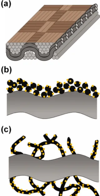
Figure9provides a schematic diagram to illustrate the underly-ing rationale for the moderate mass activity improvement from the PtRu nanoparticles on the CNTs compared to those of XC72R,
XC72R
CNCs
BP2000
CNTs
0 50 100 150 200 250 300 350ESA
(cm
2 )Figure 7. Variations in ESA on various carbon supports.
-0.2 0.0 0.2 0.4 0.6 0.8 1.0 0 100 200 300 400
I
(mAcm
-2 )E (V vs. Ag/ AgCl)
XC72R CNCs BP2000 CNTs(a)
-0.2 0.0 0.2 0.4 0.6 0.8 1.0 0 100 200 300 400I
(mA/Pt-mg
)E (V vs. Ag/AgCl)
XC72R CNCs BP2000 CNTs(b)
Figure 8. CV curves for the PtRu nanoparticles on various carbon supports
in共a兲 apparent current density and 共b兲 mass activity.
Figure 9.共Color online兲 A schematic diagram of 共a兲 carbon cloth and
CNCs, and BP2000. In the CNT scenario, an electroless-derived Ni seeding ensures the growth of large-area CNTs throughout the car-bon cloth with sufficient space in between. This allows for desirable electrolyte percolation that not only facilitates better PtRu elec-trodepositions but also promotes a larger catalytic activity for methanol electro-oxidation. In contrast, for the remaining carbon supports, the PtRu nanoparticles were deposited mostly on the car-bon surface because of the physical transfer involved. Hence, a re-duced ESA and catalyst utilization rate were expected. Our results confirmed the advantage of using an electroless deposition approach to prepare proper Ni seeding for a large-area CNT growth. With a desirable CNT formation, a significant enhancement for methanol electro-oxidation can be obtained.
Conclusion
Large-area CNTs were formed throughout the carbon cloth pre-treated with electroless-derived Ni seeds. Subsequently, a pulse elec-trodeposition was employed to fabricate PtRu nanoparticles on the CNT structure. Similar procedures were carried out on XC72R, CNCs, and BP2000. SEM and TEM images indicated that the growth of CNTs took place uniformly with PtRu evenly impreg-nated. In contrast, considerable PtRu aggregations were found on the CNCs and BP2000. The composition of PtRu was relatively unchanged among these samples. However, we observed signifi-cantly improved coulomb efficiency, PtRu loading, and ESA on the CNT-grown carbon cloth. In both apparent current density and mass activity for methanol electro-oxidation, the CNT-grown carbon cloth revealed the largest values. The observed enhancement was attrib-uted to the desirable CNT structure that allowed facile access of electrolyte.
Acknowledgments
The authors are grateful to Professor Pang Lin and Professor George Tu for their kind assistance with the laboratory equipment.
National Chiao Tung University assisted in meeting the publication costs of this article.
References
1. C. S. Karthikeyan, S. P. Nunes, L. A. S. A. Prado, M. L. Ponce, H. Silva, B. Ruffmann, and K. Schulte, J. Membr. Sci., 254, 139共2005兲.
2. F. Liu, G. Lu, and C. Y. Wang, J. Electrochem. Soc., 153, A543共2006兲. 3. E. Christoffersen, P. Liu, A. Ruban, H. L. Skriver, and J. K. Norskov, J. Catal.,
199, 123共2001兲.
4. D. C. Papageorgopoulos and F. A. de Bruijn, J. Electrochem. Soc., 149, A140
共2002兲.
5. W. Zhou, Z. Zhou, S. Song, W. Li, G. Sun, P. Tsiakaras, and Q. Xin, Appl. Catal.,
B, 46, 273共2003兲.
6. F. Vigier, C. Coutanceau, F. Hahn, E. M. Belgsir, and C. Lamy, J. Electroanal.
Chem., 563, 81共2004兲.
7. H. Liu, C. Song, L. Zhang, J. Zhang, H. Wang, and D. P. Wilkinson, J. Power
Sources, 155, 95共2006兲.
8. A. S. Aricò, S. Srinivasan, and V. Antonucci, Fuel Cells, 1, 133共2001兲. 9. Y. Takasu, T. Kawaguchi, W. Sugimoto, and Y. Murakami, Electrochim. Acta, 48,
3861共2003兲.
10. K. Y. Chan, J. Ding, J. Ren, S. Cheng, and K. Y. Tsang, Mater. Chem., 14, 505 共2004兲.
11. G. S. Chai, S. B. Yoon, J. H. Kim, and J. S. Yu, Chem. Commun. (Cambridge), 2004, 2766共2004兲.
12. C. A. Bessel, K. Laubernds, N. M. Rodriguez, and R. T. K. Baker, J. Phys. Chem.
B, 105, 1115共2001兲.
13. T. Hyeon, S. Han, Y. E. Sung, K. W. Park, and Y. W. Kim, Angew. Chem., Int. Ed., 42, 4352共2003兲.
14. S. S. Dipti, U. C. Chung, J. P. Kim, and W. S. Chung, Phys. Status Soidi A, 204, 4174共2007兲.
15. K. Vinodgopal, M. Haria, D. Meisel, and P. Kamat, Nano Lett., 4, 415共2004兲. 16. T. V. Reshetenko, H. T. Kim, and H. J. Kweon, Electrochim. Acta, 53, 3043
共2008兲.
17. Y. M. Lin, Y. M. Chang, P. W. Wu, P. Lin, Y. Y. Li, C. Y. Wu, C. F. Tsai, and K. Y. Yeh, J. Appl. Electrochem., 38, 507共2008兲.
18. M. Okada, Y. Konta, and N. Nakagawa, J. Power Sources, 185, 711共2008兲. 19. Y. Lin, X. Cui, C. Yen, and C. M. Wai, J. Phys. Chem. B, 109, 14410共2005兲. 20. S. Takenaka, H. Matsumori, H. Matsune, E. Tanabe, and M. Kishida, J.
Electro-chem. Soc., 155, B929共2008兲.
21. X. Wang, M. Waje, and Y. Yan, Electrochem. Solid-State Lett., 8, A42共2005兲. 22. K. Shimizu, I. F. Cheng, J. S. Wang, C. H. Yen, B. Yoon, and C. M. Wai, Energy
Fuels, 22, 2543共2008兲.
23. C. Y. Du, T. S. Zhao, and Z. X. Liang, J. Power Sources, 176, 9共2008兲. 24. W. Li, X. Wang, Z. Chen, M. Waje, and Y. Yan, Langmuir, 21, 9386共2005兲. 25. C. C. Chien and K. T. Jeng, Mater. Chem. Phys., 99, 80共2006兲.
26. G. Girishkumar, K. Vinodgopal, and P. V. Kamat, J. Phys. Chem. B, 108, 19960 共2004兲.
27. M. C. Tsai, T. K. Yeh, and C. H. Tsai, Mater. Chem. Phys., 109, 422共2008兲. 28. P. Sivakumar and V. Tricoli, Electrochim. Acta, 51, 1235共2006兲.
29. C. C. Yang, S. J. Chiu, and C. T. Lin, J. Power Sources, 177, 40共2008兲. 30. T. C. Liu and Y. Y. Li, Carbon, 44, 2045共2006兲.
31. Y. M. Chang, Y. C. Hsieh, and P. W. Wu, Diamond Relat. Mater., 18, 501共2009兲. 32. C. Y. Wu, P. W. Wu, P. Lin, Y. Y. Li, and Y. M. Lin, J. Electrochem. Soc., 154,
B1059共2007兲.
33. A. N. Gavrilov, O. A. Petrii, A. A. Mukovnin, N. V. Smirnova, T. V. Levchenko, and G. A. Tsirlina, Electrochim. Acta, 52, 2775共2007兲.
34. M. C. Tsai, T. K. Yeh, Z. Y. Juang, and C. H. Tsai, Carbon, 45, 383共2007兲. 35. Z. D. Wei, S. G. Chen, Y. Liu, C. X. Sun, Z. G. Shao, and P. K. Shen, J. Phys.
Chem. C, 111, 15456共2007兲.
36. T. Navessin, M. Eikerling, Q. Wang, D. Song, Z. Liu, J. Horsfall, K. V. Lovell, and S. Holdcroft, J. Electrochem. Soc., 152, A796共2005兲.
37. Z. Liu, X. Y. Ling, B. Guo, L. Hong, and J. Y. Lee, J. Power Sources, 167, 272 共2007兲.