Pergamon P I I : S 0 0 3 8 – 0 9 2 X ( 0 1 ) 0 0 0 4 2 – 1 Printed in Great Britain 0038-092X / 01 / $ - see front matter
www.elsevier.com / locate / solener
COLLECTOR SELECTION FOR SOLAR EJECTOR COOLING SYSTEM
† ,* * ** **
B. J. HUANG , V. A. PETRENKO , I. YA. SAMOFATOV and N. A. SHCHETININA
*Department of Mechanical Engineering, National Taiwan University, Taipei 106, Taiwan **Odessa State Academy of Refrigeration, Odessa 270026, Ukraine
Received 21 September 1999; revised version accepted 27 March 2001 Communicated by BYARD WOOD
Abstract—The performance of a solar ejector cooling system is simulated using three different collectors: a
conventional flat plate collector, a high efficiency flat plate collector and a vacuum-tube collector. It is shown that with the proper selection of the generating temperature an optimum COP can be achieved. The solar ejector cooling system using the single-glazed solar collector with selective surface and an enhanced air insulating layer can be most economical when operated at the optimum generating temperature of the ejector cooling machine. In this case, the solar system cost is around 1 USD per watt of cooling capacity for air conditioning applications. 2001 Published by Elsevier Science Ltd.
1. INTRODUCTION 2. DESIGN OF A SOLAR EJECTOR COOLING
SYSTEM A solar cooling / refrigeration system which
con-verts the solar thermal energy into cooling effect We have been investigating ejector cooling
has long been an interesting subject for scientists machines (ECM) using R113 and R142b as the
and engineers. In practical application, a solar working fluids (Huang et al., 1985; Petrenko and
collector is used to absorb the solar thermal Shchetinina, 1992; Petrenko et al., 1997;
energy first. The heat is then used to drive a Shchetinina et al., 1987a,b). In a recent study, we heat-driven cooling machine to produce a cooling found that a solar ejector cooling system (SECS) effect. The total cost of a solar cooling system using R141b as the working fluid and utilizing a thus includes the costs of the solar energy collect- specially-designed ejector can obtain a better
ing system and the heat-driven cooling machine. COP than before (Huang et al., 1998, 1999;
ECM
For a heat-driven cooling machine, the required Huang and Chang, 1999). An ECM using R141b
generating temperature may be high (higher than as the working fluid is thus chosen for the SECS 808C). A high-performance vacuum-tube collector in the present study. Fig. 1 is the schematic of a with high cost is thus recommended and the total single-stage SECS.
cost of a solar cooling system becomes unaccept- A SECS consists of an ECM and the solar
able. collector system. Solar thermal energy is absorbed
Whether a cheaper solar collector like a flat- by the solar collector and used to drive the ECM.
plate collector can be used for a solar cooling The generating temperature T of the ECM is
g
system still remains an unresolved question for usually high ( . 708C) in order to obtain a better many researchers. By utilizing a high-quality
performance. The solar collector thus needs to selective surface, good insulation design and
high-operate at a higher temperature ( . 808C). Vacuum performance glass cover, the flat-plate solar
col-tube solar collectors have been recommended by lector can be made with relatively high efficiency
many researchers for SECS in order to have at low cost. In addition, the efficiency of
heat-higher energy collection efficiency at a high inlet driven cooling machines has also been improved
temperature. However, the cost is very high. For a dramatically. The present study intends to
re-SECS which requires the collector to operate at a examine the feasibility of using less expensive
temperature in the range 80–1008C, a cheaper flat-plate solar collectors to provide the energy for
flat-plate type collector may be used though its a solar cooling system.
energy collecting efficiency is relatively low. For a SECS, selection of the design point for
† condensing temperature T , evaporating tempera-c
Author to whom correspondence should be addressed.
ture T and generating temperature T of the ECM
Tel.: 1886-2-2363-4790; fax: 1886-2-2364-0549; e g
e-mail: [email protected] is very important. The method of the design of an 269
the optimal Tg that corresponds to a maximum COP is determined in the present study.o
3. SOLAR COLLECTOR SELECTION FOR EJECTOR COOLING SYSTEM
For the heat supply of SECS we selected three commercially available solar collectors for com-parison. Type A is a low-cost specially designed single-glazed flat-plate solar collector with a selective surface. Type B is a conventional single-glazed solar collector with a selective surface. The difference between type A and type B collector lies in the insulation layer design. Type A collec-tor uses a 10-cm layer of air space (insulation) beneath the glass cover. Type C is a vacuum-tube solar collector with tube-in-sheet fin. The steady-state thermal performance curves of these solar collectors are (T 2 T )i a ]]] h 5 0.80 2 Csc A I , T 2 m Fig. 1. Schematic diagram of solar ejector cooling system.
]] C 5 3.5A W K (Type A) (2) (T 2 T )i a ]]] h 5 0.80 2 Csc B I , T
ECM using R141b as the working fluid has been
2
studied by Huang et al. (1999) and Huang and m
]]
C 5 5.7B (Type B) (3)
Chang (1999). It has been shown that the design W K
parameters of an ejector are dependent on the
(T 2 T )i a
operating conditions (T , P , T , P , T , P ) whichc c g g e e h 5 0.80 2 C ]]],
sc C I
are related to the specific needs of the application T
2
and the equipment capability. The evaporation m
]]
C 5 2.0 (Type C) (4)
temperature T is usually in the range of 5–108Ce C W K
for air conditioning purposes and about 25 or
268C for refrigeration purposes. The condensing where I is the incident solar radiation upon theT
22
temperature T depends both on the heat-rejectingc collector aperture (W m ); T and Ti a are the
equipment used for the condenser and on the type collector inlet and the ambient temperatures,
of the cooling fluid (water or air). For different respectively. Eqs. (2) and (3) were obtained from climatic conditions it spreads over a wide range, testing results of the solar energy lab at the usually 28–408C. In the present study, the design National Taiwan University for the type A and B
calculation of a R141b ECM follows the method collectors. Eq. (4) for the type C collector was
developed by Huang et al. (1999) and Huang and obtained from the manufacturer.
Chang (1999). In the present study, we first determine the
The selection of generating temperature Tg is COP of an ECM for different climatic conditions especially important for SECS since it affects not (T 528–408C) in an air conditioning regimec
only the coefficient of performance of the ejector- (T 588C) and a refrigeration regime (T 5 268C)e e
cooling machine (COPECM), but also the ef- for a wide range of generating temperatures
ficiency of the solar collector h . An increase insc (T 570–1308C). The calculation follows theg
Tg increases the COPECM but decreases the h .sc method developed by Huang et al. (1999) and
Since the overall efficiency of SECS is the Huang and Chang (1999). The results are shown
product of the particular coefficients in Fig. 2.
As seen from Fig. 2 COPECM increases with
Fig. 2. Variation of COPECMwith T for T 588C and T 5 268C at different T .g e e c
can reach the value 0.7 at T 51008C, T 5288Cg c ance of a SECS. Comparison between the
differ-and T 588C.e ent types of solar collectors for heat supply of
According to the performance of the ECM SECS was first made. The solar thermal energy is
shown in Fig. 2, we then evaluate the perform- transported to the generator by a heating medium
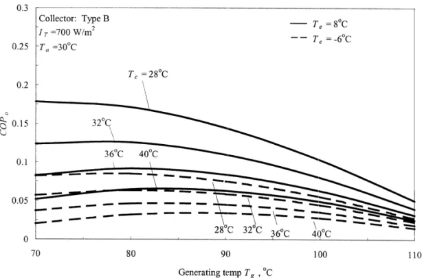
Fig. 4. Variation of COP with T for T 588C and T 5 268C at different T (collector type B).o g e e c
(water). The inlet temperature of the solar collec- a given T , T , and T , according to Eq. (1).g c e
tor was assumed 108C higher than the generating Plotting COP for various T , T , and T , we cano g c e
temperature of the ECM, i.e. T 5 T 1108C. Thei g find the optimum design of a SECS.
incident solar radiation is assumed at I 5700 WT Figs. 3–5 show the variation of COP with To g
22
m and the ambient temperature at T 5308C.a for T 588C and T 5 268C at T 528, 32, 36 ande e c
From this, the thermal efficiency of a solar 408C. Each curve on Figs. 3–5 has a maximum
collector hsc can be calculated. The overall COP value, which corresponds to the optimum generat-of the solar cooling system COP is evaluated foro ing temperature of the ejector cooling machine.
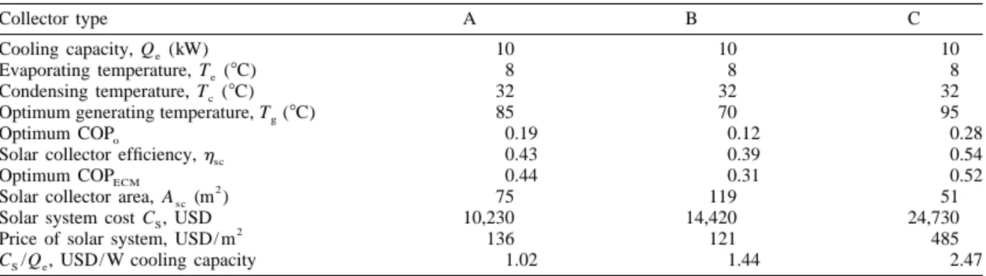
Table 1. A solar ejector air-conditioning system using different types of solar collectors
Collector type A B C
Cooling capacity, Q (kW)e 10 10 10
Evaporating temperature, T (8C)e 8 8 8
Condensing temperature, T (8C)c 32 32 32
Optimum generating temperature, T (8C)g 85 70 95
Optimum COPo 0.19 0.12 0.28
Solar collector efficiency, hsc 0.43 0.39 0.54
Optimum COPECM 0.44 0.31 0.52
2
Solar collector area, Asc(m ) 75 119 51
Solar system cost C , USDS 10,230 14,420 24,730
2
Price of solar system, USD/ m 136 121 485
C /Q , USD/ W cooling capacityS e 1.02 1.44 2.47
Table 2. A solar ejector refrigerating system using different types of solar collectors
Collector type A B C
Cooling capacity, Q (kW)e 1.0 1.0 1.0
Evaporating temperature, T (8C)e 26 26 26
Condensing temperature, T (8C)c 32 32 32
Optimum generating temperature, T (8C)g 90 75 100
Optimum COPo 0.103 0.063 0.161
Solar collector efficiency, hsc 0.41 0.35 0.52
Optimum COPECM 0.25 0.18 0.31
2
Solar collector area, Asc(m ) 13.9 22.7 8.9
Solar system cost C , USDS 1895 2752 4315
2
Price of solar system, USD/ m 136 121 485
C /Q , USD/ W coolingS e 1.90 2.75 4.32
The optimum COP decreases with increasing To c The collector efficiency values in Tables 1 and
and decreasing T . It can be seen that, fore 2 were calculated from Eqs. (2)–(4) using the
obtaining a higher solar collector efficiency, Tg inlet temperature T 5 T 1 108C.i g
can be chosen at a temperature about 10 to 158C lower than the corresponding optimum values
4. DISCUSSION AND CONCLUSION with only very little effect on the optimum COP .o
The total installation cost of the solar collector In the present paper, we have shown that a system is estimated. Table 1 shows the SECS for SECS using conventional single-glazed solar col-air-conditioning application at a fixed cooling lector with selective surfaces can be most econ-capacity (10 kW). It is interesting to note that, omical by a proper choice of optimum generating with a proper selection of the generating tempera- temperature of the ECM. In this case, for the ture, an optimum COPECMcan be determined. For optimum generating temperature in the range 85– the flat-plate collectors (type A and type B), hsc 908C, the solar collector efficiency can reach
makes little difference (0.43 against 0.39) but 0.43–0.41 and the overall COP of a SECS
o
COPECM makes a larger difference (0.44 against reaches about 0.19 for air conditioning purposes
0.31). Though hsc and COPECM are higher (0.54 and 0.10 for refrigeration purposes. The solar
and 0.52, respectively) for a SECS using the solar system cost is around 1 USD per watt of cooling collector type C, the cost of the vacuum-tube solar capacity in air conditioning applications. The unit collector (type C) is very high. The unit cost of a system cost C /Q for refrigeration applications is
S e
solar system C /QS e using type C collector be- about one time bigger than that for the
air-con-comes the highest. ditioning application.
It is shown that the SECS using type A collector is most economical. The unit solar
cooling system cost is around 1 USD per watt of NOMENCLATURE
cooling capacity.
2
Asc total solar collector area, m Table 2 shows the case of a SECS for the
CS solar collector cost, USD
refrigeration application. It shows again that the I solar radiation intensity incident upon collector T
22
SECS using type A collector is most economical. aperture, W m
Qe cooling capacity, kW
The unit cost of the solar system C /Q for theS e T ambient temperature to collector, 8C
a
refrigeration application is about one time higher T critical condensing temperature of ejector cooling c
Te evaporating temperature of ejector cooling ma- Huang B. J., Chang J. M., Wang C. P. and Petrenko V. A.
chine, 8C (1999) A 1-D analysis of ejector performance. Int. J. Refrig.
Tg generating temperature of ejector cooling machine, 22, 354–364.
8C Huang B. J. and Chang J. M. (1999) Empirical correlation for
Ti inlet temperature to collector, 8C ejector design. Int. J. Refrig. 22, 379–388.
COPo coefficient of performance of solar cooling system Huang B. J., Jiang C. B. and Hu F. L. (1985) Ejector (5cooling power / solar energy input), dimension- performance characteristics and design analysis of jet
less refrigeration system. ASME J. Eng. Power 107, 792–802.
COPECM coefficient of performance of ejector cooling ma- Petrenko V. A. and Shchetinina N. A. (1992) A solar vapor chine (5cooling power / heat energy input), di- ejector refrigerator testing in air conditioning regime. In
mensionless Proceedings World Renewable Energy Congress, September
hsc thermal efficiency of solar collector, dimensionless 13 –18, Reading, UK, pp. 1023–1029.
Petrenko V. A., Bulavin I. V. and Samofatov I. Y. (1997) Investigation of the methods increasing the efficiency of Acknowledgements—The present study was supported by the solar ejector cooling and refrigeration systems. In Proceed-National Science Council of ROC, Taiwan, through grant no. ings ISES 1997 Solar World Congress, August 24–30,
NSC88-2212-E-002-051. Tajeon, Korea, Vol. 4, pp. 330–341.
Shchetinina N. A., Zhadan S. Z. and Petrenko V. A. (1987a) Experimental investigation of a solar ejector Freon re-frigerating machine. Geliotekhnika 23(3), 66–69.
REFERENCES
Shchetinina N. A., Zhadan S. Z. and Petrenko V. A. (1987b) Huang B. J., Chang J. M., Petrenko V. A. and Zhuk K. B. Comparison of the efficiency of various ways of heating the (1998) A solar ejector cooling system using refrigerant generator of a solar ejector Freon refrigerating machine. R-141b. Solar Energy 64(4–6), 223–226. Geliotekhnika 23(4), 71–74.