Design, operation and morphological effects
of bypass tunnels as a sediment routing
technique
Robert M. Boes, Michelle Mü ller-Hagmann, and Ismail Albayrak
Abstract
Sediment Bypass Tunnels (SBTs) are a sediment routing technique. During floods, sediment-laden water is conveyed through the tunnel to the dam tailwater. SBTs feature several advantages over other measures against reservoir sedimentation. First of all, SBTs have demonstrated to be quite effective with sediment bypass efficiencies of up to more than 90%, thus considerably extending the reservoir life, i.e. the theoretical duration until the reservoir is completely filled with sediment. Secondly, they have positive effects on downstream eco-morphology, because sediment conveyance may significantly decelerate or even stop riverbed incision and increase the habitat quality and morphological variability below a dam reservoir. Mainly sediments provided from upstream river reaches are conveyed through SBTs since remobilization of accumulated sediments in the reservoir hardly occurs. An SBT can thus greatly improve the sediment continuity despite river impoundment by dams. In this paper the main design features, operational aspects and eco-morphological effects of SBTs are presented.
Keywords: sediment routing, reservoir sedimentation, sediment continuity, riverbed incision, eco-morphology
1 General application range of sediment bypass tunnels
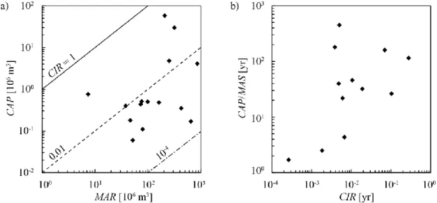
SBTs are considered an adequate measure against reservoir sedimentation for small to medium-sized reservoirs with capacity-inflow ratios of about CIR=0.003 to 0.3 (Figure 1a), impounding up to a few million m3 of water and featuring typical reservoir life values
of up to some decades or at most a few hundreds of years (Figure 1b) (Sumi and Kantoush, 2011; Müller-Hagmann, 2017). Worldwide, there are only a few larger reservoirs with storage capacities of some dozen million m3 featuring an SBT. Figure 1a shows the relation between the reservoir capacity CAP and the mean annual runoff MAR of the reservoir of existing SBTs. The average residence time, determined by the capacity-inflow ratio, varies around CIR = 0.01 yr, indicating that most SBTs are constructed at daily or weekly reservoirs (Müller-Hagmann, 2017). For these small- to medium-sized reservoirs, a large amount of the suspended sediments does not settle due to the relatively short residence time and is thus discharged via the outlet works. Hence, bed load aggradation and delta formation are more critical than the deposition of fine sediments. However, as floods up to the SBT discharge capacity are conveyed around the dam
without being damped in the reservoir, SBTs are most appropriate in mountainous regions with relatively large river slopes and high water availability. In contrast, in arid environments with pronounced dry seasons the flood runoff is of prime importance for reservoir filling, thus impeding or limiting the use of SBTs. Moreover, tunnelling cost favours the use of SBTs at rather small reservoirs due to short tunnel length. The SBT tunnel length is generally shorter than 2 km, and the slope typically varies between 1 and 5%. SBTs can substitute reservoir flushing, or represent a complementary measure, e.g. in combination with drawdown flushing (De Cesare et al. 2015, Beck et al. 2016). An overview of worldwide SBTs in operation, under construction or planned as well as on state-of-the-art SBT research is given in Boes (2015) and Sumi (2017). To reduce negative effects of hydro-abrasion occurring at SBTs which may cause pronounced maintenance cost, it is recommended to (i) optimize the hydraulic design to limit the particle impact, and (ii) select sustainable and optimal abrasion-resistant invert lining material (Boes et al., 2014).
Fig. 1: a) Reservoir capacity (CAP) vs. mean annual runoff (MAR) with CIR = 1, 0.01 and 10−4 represented by the bold, the dashed and the dot-dashed lines, respectively; b) reservoir life span (= CAP/MAS) vs. CIR of reservoirs equipped with an SBT (from Müller-Hagmann, 2017)
2 Bypassing discharge capacity and target sediment granulometry
The choice of the SBT discharge capacity depends above all on an economic tunnel cross-sectional area and on the hydrological catchment conditions. According to Vischer et al. (1997) and Sumi et al. (2004), SBT design discharges typically correspond to between a one- and a ten-year flood peak discharge. The surplus flow exceeding the SBT discharge capacity has to be conveyed to the downstream reservoir reach. Because a routing of all incoming sediments is achieved only up to the SBT design discharge, a rather high flood return period should be selected. Particularly for reservoirs with small catchments impounded by embankment dams, a recurrence interval of up to 100 years may be preferable to complement the service spillway capacity. Absolute values of SBT design
discharges currently in service or under construction range from 40 to 400 m3/s (Auel and Boes, 2011; Auel, 2014; De Cesare et al., 2015; Ohiro et al., 2017; Müller-Hagmann, 2017). Higher capacities of 1000 m3/s are found in Taiwan, e.g. at Nanhua and Tsengwen reservoirs (Ohiro et al., 2017). The intake structures of these tunnels are located within the reservoir, corresponding to type (B) SBTs (see 3.2), and are always submerged. Such kind of SBTs may thus be classified as sediment venting tunnels. The duration of SBT operation ranges from 1 day/yr to more than 100 days/yr, depending on local hydrology and reservoir size. The median operation duration of SBTs amounts to 5 to 6 days/yr (Müller-Hagmann, 2017).
The target sediment grain size distribution and volumes of both bed load and suspended load to be bypassed through an SBT have to be evaluated site-specifically with regard to the total sediment yield, acceptable reservoir storage loss, and sediment flushing and ven-ting capacity of other hydraulic structures including bottom outlets and power intakes. For existing SBTs, the median particle sizes of the mean and the 90% percentile diameters, i.e. dm and d90, amount to 60 mm and 200 mm, respectively (Müller-Hagmann, 2017).
Most SBTs are designed and operated to convey as much incoming sediment as possible, from bed load to suspended fines. However, especially for long SBTs such as at Miwa dam, Japan, the bed load is preferably trapped and dredged upstream, and only the sus-pended load is bypassed around the dam to limit hydro-abrasive wear of the SBT invert (Hagmann et al., 2016; Sawagashira et al., 2017a). This also holds for Taiwanese sedi-ment venting tunnels, whose target grain sizes are in the silt range, i.e. below 0.063 mm. For inflow discharges exceeding the SBT design capacity, suspended sediments may however still enter the reservoir and accumulate to some extent in the downstream reser-voir reach, while the conveyance of bed load towards the SBT intake with high bypass efficiency should be aimed at by means of a guiding structure (Auel and Boes 2011).
3 Hydraulic design
3.1 General considerations
A typical SBT layout includes a regulated intake structure, followed by a mostly short and steep flow accelerating reach (Fig. 2a) and a more gently sloped standard cross-section up to the outlet structure with a subsequent energy dissipator. Free-surface flow is preferred, but pressurized flow for the design discharge may also occur, depending on the gate location determining the control section. SBTs as Patrind, Pakistan (Beck et al., 2016), or Rizzanese, France (Carlioz and Peloutier, 2014), are gate-controlled from the downstream end, due to site constraints disabling a gate installation at the inlet. In such cases, free-surface, mixed, and pressurized flows may occur, depending on the discharge scenario (Boes et al., 2017). Regarding flow velocity, there is a trade-off: while it must be sufficiently high to avoid sediment deposition, the maximum velocities should be as small as possible to control the extent of invert abrasion (Hagmann et al., 2016).
3.2 Intake location and structure
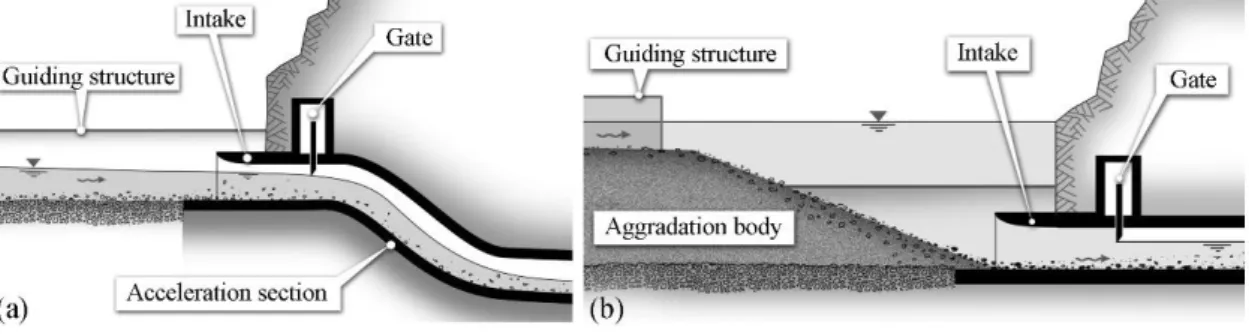
Two different locations are generally adopted for the SBT intake, both affecting the entire SBT design and the reservoir operation during sediment routing. Its most common location, applied for the majority of SBTs, is at the reservoir head (type (A), Fig. 2a). Another suitable location is within the reservoir close to the dam, e.g. for retrofitting existing, partially silted reservoirs with a SBT preferably just downstream of the pivot point of the aggradation body (type (B), Fig. 2b). Pros and cons and bypass efficiency evaluation of both locations are discussed by Auel and Boes (2011) and in the accompanying paper (Albayrak et al., 2019), respectively.
Fig. 2: Sketches of SBT intakes of type (a) (A) with free-surface inflow, (b) (B) with pressurized inflow (Auel and Boes, 2011)
The SBT intake typically consists of an intake trumpet followed by a sluice or a radial gate. The gate is closed during normal reservoir operation and opened during flood events to route the sediment-laden discharge through the SBT. The design of the intake depends directly on the selection of the intake location given above.
If the intake is located at the reservoir head (type (A)), the discharge is conveyed into the SBT under free-surface flow (Fig. 2a). The tunnel invert level at the intake is flush to the river bed. Downstream of the gate, the discharge has to be accelerated to generate super-critical flow. This is achieved by a short and steep acceleration section. For type (B) intakes, the tunnel invert level should be lower than the surrounding aggradation body. A certain energy head is thus available and the discharge is conveyed into the intake trumpet under pressurized flow (Fig. 2b). However, downstream of the gate, the discharge is routed through the SBT under free-surface flow. Due to the significant energy head, the flow velocity downstream of the gate is high, so that an acceleration section is not needed. Keeping floating debris away from an SBT intake is advisable to prevent clogging by large wood in the SBT. Racks consisting of vertical poles or bars should be applied with care as sediment transport may become interrupted if wooden debris is retained at these structures (Hagmann et al., 2015). From experience with driftwood retention racks involving vertical poles, the sediment transport capacity is considerably reduced once a significant amount of floating debris is trapped (Schmocker and Weitbrecht, 2013).
3.3 Guiding structure
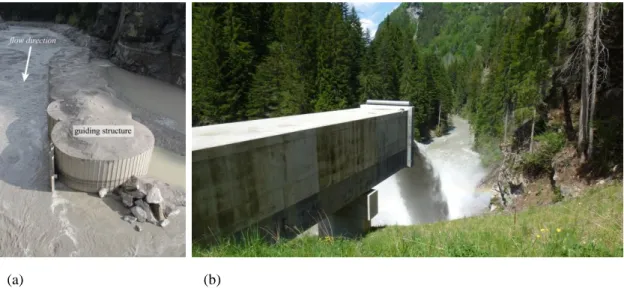
The guiding structure, also referred to as diversion weir or sill, sediment check dam or partition dam, ensures that the incoming sediment-laden flow is conveyed to the SBT intake. The guiding structure, consisting of cofferdams (Fig. 3a) or embankment structures, is located next to the intake structure in most existing SBTs (Vischer et al., 1997; Sumi et al., 2004), crossing the reservoir from the intake to the opposite reservoir bank. The guiding structure should preferably not be overtopped during SBT operation to avoid sediment input and accumulation in the reservoir. However, if the flood event exceeds the SBT design capacity, the guiding structure has to be securely overtopped or openings in the guiding structure are to be designed to lead the surplus flow to the dam outlet structures (Auel and Boes, 2011). In this case, the bed load can still be conveyed to the SBT with high bypass efficiency thanks to the guiding structure.
(a) (b)
Fig. 3: SBT Solis, Switzerland, with (a) circular cell cofferdam as guiding structure at the intake during operation on May 3rd,2013, reservoir level at approx. 816 m a.s.l, and (b) cantilevering outlet
structure on May 23rd, 2014 (downstream view) (adapted from Oertli and Auel, 2015)
3.4 Tunnel layout and cross-section
The tunnel connects the upstream SBT intake with the downstream outlet structure located at the dam tailwater. Typical tunnel lengths of existing SBTs vary between 250 and 4300 m. To keep the cross-section small and due to the large longitudinal slope, supercritical flow occurs. Therefore, the flow is accelerated at the inlet either by pressurized flow upstream of the gate or by a steep section downstream. For the former, typically of type (B), the flow decelerates from the vena contracta just downstream of the gate, while for the latter, typically of type (A) SBTs, the flow reaches a maximum at the end of the acceleration section and then slightly decelerates in streamwise direction. In both cases the flow remains supercritical along the entire SBT, with average outflow velocities slightly above 11 m/s at design discharge, while the maximum velocities are about 14 m/s on average. For sediment venting tunnels in Taiwan, velocities at design
discharge amount to 20 to 30 m/s (Ohori et al., 2017). The susceptibility for cavitation inception should be checked for such high-velocity flows. Bends in plan view should be avoided whenever possible to reduce shock waves and secondary currents, causing locally high specific sediment transport rates and concentration of hydro-abrasive invert wear. The cross-section of most SBTs is of horseshoe or archway shape with hydraulic sections ranging from 20 to 30 m2, resulting in Froude numbers between 1.4 and slightly above 3. A circular cross-sectional shape should be avoided as this would favour concentrated sediment transport at the lowest invert point causing severe abrasion problems. Another drawback of circular versus archway- or horseshoe-shaped cross-section is the challenging trafficability during tunnel construction and maintenance.
3.5 Outlet structure
The sediment-laden flow is discharged at the outlet structure into the tailwater down-stream of the dam (Fig. 3b). The following aspects regarding its design have to be respected: (i) check for sufficient transport capacity in the downstream river reach to avoid sediment deposition in the outlet vicinity and further downstream; (ii) locate SBT outlet sufficiently far away from the dam outlet structures to avoid backwater effects in their vicinity; (iii) design a drop from the SBT outlet to the river reach to avoid backward aggradation in the tunnel; (iv) keep angle in plan view between centreline of the SBT outlet and the river thalweg mild to reduce erosion impact on the opposite river bank; (v) regularly monitor scour due to jet impact from the SBT outlet (Auel and Boes, 2011).
4 Tunnel operation and monitoring techniques
Depending on the SBT intake location, reservoir operation during sediment routing varies. For type (A) SBTs, the gate is opened during floods and the sediment-laden flow is routed through the tunnel under free-surface flow. The reservoir level can be kept at full supply level. The incoming flow and sediment are conveyed into the dam tailwater, independent of the reservoir level. For type (B) SBTs, the reservoir level has to be lowered prior to a flood event depending on the distance of the reservoir head to the tunnel intake. The reservoir reach upstream of the intake should be subjected to free-surface flow to ensure high transport capacity so that incoming sediment is conveyed toward the intake. The reservoir level has to be kept at a certain target elevation to avoid the interruption of sediment transport (Auel and Boes, 2011; Müller-Hagmann, 2017).
SBTs should be equipped with instrumentation to monitor and follow up their operation and behaviour, e.g. regarding flow velocities, sediment transport and state of invert abrasion. This allows for the collection of operational data, bypass efficiency rating, abrasion and damage observation, and an analysis of flushing events to optimize efficiencies and to minimize abrasion (Hagmann et al., 2016). If real-time monitoring techniques are applied, the operation may even be adapted during the bypassing event,
e.g. to maximize the bypassed sediment volume. The main parameters to be monitored in real-time are the reservoir water level (for type (B) SBTs), the suspended sediment con-centration (e.g. by means of turbidimeters), intake gate position (e.g. by displacement transducers), tunnel flow velocity (e.g. by radar), tunnel flow depth (e.g. by pressure sensors) and, optimally, bed load transport rate (e.g. by means of geophones or hydro-phones). 3D laser scanning can be effectively utilized for periodical monitoring of abrasion patterns and depths.
5 Eco-morphological effects of SBT operation
Re-establishing the sediment continuum in a river is one of the main purposes of SBTs. They allow for conveyance of sediments, both bed and suspended loads, from the up-stream river to the downup-stream reach, having the potential to enhance river morphology and habitat quality of the often sediment-depleted river reaches downstream of dams. The routing of large sediment loads around the reservoir during flood events resembles the natural riverine conditions, leading to a reduced erosion and river incision potential in the downstream reach. This in turn may positively affect the river ecosystem, altering the habitat conditions for the biota, particularly fish and macro-invertebrates (Facchini et al., 2015).
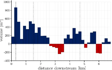
Facchini et al. (2015) examined the eco-morphological effects in the downstream river system by monitoring the river bed elevation and its grain size distribution at different cross-sections downstream of the Solis SBT outlet. The Albula river bed levels were measured in several river cross-sections along some 6 km from the SBT outlet in 2012 and 2013, and after a large flood that occurred in August 2014, while the grain size distribution was measured in the same years in the middle and downstream portions, some 3 and 6 km from the outlet, respectively. The river bed level changes between October 2014 and October 2016 were additionally measured using airborne LiDAR of the river bathymetry. The data analyses showed that flood events with SBT operation cause considerable changes in the river morphology (Fig. 4) and in the grain size distribution of the bed material. Martin et al.’s (2015) investigation of the same river reach shows that the habitat quality of the river is affected by both the Solis dam spillway and SBT operations, whereby the extent of disturbance increases with discharge. Relative to the frequency of these events, the recovery duration is shorter of the order of several weeks to months. Auel et al. (2016) monitored four reservoirs with SBTs in Japan (Asahi, Ko-shibu) and Switzerland (Solis, Pfaffensprung) to analyse their effects in terms of up- to downstream morphological and biotic changes. Sediment grain size distributions (GSD), local bed characteristics, microhabitat abundance and invertebrate richness were analysed. It was found that the GSD at reservoirs with newly established SBTs are finer in the up- and relatively coarse (armoured) in their downstream reaches due to lack of conveyed sediments in the past. An analysis of biotic data directly below the dams, but upstream of
the SBT outlet revealed that microhabitat richness is low, whereas lentic species abun-dance is high compared to the upstream reach. However, these differences decrease fur-ther downstream. Microhabitat and invertebrate richness in the downstream adjust to the upstream values with increasing number of operation years, clearly highlighting the posi-tive effects of long-term SBT operation. At several Japanese dams, the river reaches downstream of SBTs are regularly monitored as to the status of aquatic and terrestrial ecology as well as turbidity and morphology. The case studies downstream of Asahi dam (Fukuroi, 2012), Miwa dam (Sawagashira et al., 2017b), and Solis dam (Facchini, 2017) revealed positive effects of the SBTs on morphology and habitats , with the eco-morpho-logical status quickly improving after a few SBT operations, while it takes much longer to reach quasi pre-dam conditions.
Fig. 4: Sediment budget segregation over 200 m reaches along the Albula river downstream of SBT Solis, Switzerland, after the 2014 flood (resulting from DEM of difference between October 2014 and October 2016); positive values (blue bars) refer to deposition, negative values (red bars) to erosion, dashed lines indicate tributary confluences (Facchini, 2017)
6 Conclusions
To counteract reservoir sedimentation, different techniques may be implemented at dam sites. Among the techniques used to route sediments around dams, sediment bypass tunnels (SBTs) are implemented with the twofold aims of reducing reservoir sedimenta-tion and maintaining or restoring sediment regimes in the downstream river reaches. SBTs have proven to significantly reduce the sediment accumulation in reservoirs during flood events. Herein, SBT elements such as intake, guiding structure, tunnel and outlet are discussed as to their design. In addition, operational aspects and the value of monitoring techniques are presented. A number of river reaches below SBTs have been systemati-cally monitored as to morphological changes and habitat development. These studies
clearly demonstrated the positive effects of SBTs to re-establish conditions close to pre-dam status.
Acknowledgement
VAW’s research on SBTs is embedded in the framework of the Swiss Competence Centre of Energy Research – Supply of Electricity (SCCER-SoE), an initiative funded by the Swiss Confederation through Innosuisse (Swiss Innovation Agency).
References
Albayrak, I., Müller-Hagmann, M., Boes, R.M. (2019). Efficiency evaluation of Swiss sediment bypass tunnels. Proc. 3rd Intl. Workshop on Sediment Bypass Tunnels, Taipei, Taiwan.
Auel, C. (2014). Flow characteristics, particle motion and invert abrasion in sediment bypass tunnels. VAW-Mitteilung 229 (R. Boes, ed.), Laboratory of Hydraulics, Hydrology and Glaciology (VAW), ETH Zürich, Switzerland.
Auel, C., Boes, R.M. (2011). Sediment bypass tunnel design - review and outlook. Proc. ICOLD Symposium „Dams under changing challenges“ (A.J. Schleiss & R.M. Boes, eds.), 79th Annual
Meeting, Lucerne. Taylor & Francis Group, London, UK: 403-412.
Auel, C., Kobayashi, S., Sumi, T., Takemon, Y. (2016). Effects of sediment bypass tunnels on sediment grain size distribution and benthic habitats. River Sedimentation (Wieprecht et al., eds.), ISBN 978-1-138-02945-3, Taylor & Francis, London: 825-832.
Beck, C.; Lutz, N.; Lais, A.; Vetsch, D.; Boes, R.M. (2016). Patrind Hydropower Project, Pakistan – Physical model investigations on the optimization of the sediment management concept. Proc. Hydro 2016, Montreux, Switzerland.
Boes, R. (ed.) (2015). Proc. 1st Intl. Workshop on Sediment Bypass Tunnels, VAW-Mitteilung 232,
Laboratory of Hydraulics, Hydrology and Glaciology (VAW), ETH Zürich, Switzerland. Boes, R.M., Auel, C., Hagmann, M. & Albayrak, I. (2014). Sediment bypass tunnels to mitigate reservoir
sedimentation and restore sediment continuity. Reservoir Sedimentation (Schleiss, A.J., De Cesare, G., Franca, M.J., Pfister, M., eds.), ISBN 978-1-138-02675-9, Taylor & Francis, London, UK: 221-228.
Boes, R.M.; Beck, C.; Lutz, N.; Lais, A.; Albayrak, I. (2017). Hydraulics of water, air-water and sediment flow in downstream-controlled sediment bypass tunnels. Proc. 2nd Intl. Workshop on
Sediment Bypass Tunnels, paper FP11 (T. Sumi, ed.), Kyoto University, Japan.
Carlioz, P., Peloutier, V. (2014). Implementing a sediment transit gate at Rizzanese dam. Proc. Intl., ICOLD Sympoium on Dams in a Global Environmental Challenges, Bali, Indonesia, Abstract number 346.
De Cesare, G., Manso, P., Daneshvari, M., Schleiss, A.J. (2015). Laboratory research: Bed load guidance into sediment bypass tunnel inlet. Proc. 1st Intl. Workshop on Sediment Bypass Tunnels.
VAW-Mitteilung 232 (R. Boes, ed.), Laboratory of Hydraulics, Hydrology and Glaciology (VAW), ETH Zürich, Switzerland: 169-179.
Facchini, M. (2017). Downstream morphological effects of Sediment Bypass Tunnels. VAW-Mitteilung 243 (R. Boes, ed.), Laboratory of Hydraulics, Hydrology and Glaciology (VAW), ETH Zürich, Switzerland
Facchini, M., Siviglia, A., Boes, R.M. (2015). Downstream morphological impact of a sediment bypass tunnel – preliminary results and forthcoming actions. Proc. 1st Intl. Workshop on Sediment
Bypass Tunnels. VAW-Mitteilung 232 (R. Boes, ed.), Laboratory of Hydraulics, Hydrology and Glaciology (VAW), ETH Zürich, Switzerland: 137-146.
Fukuroi, H. (2012). Damage from Typhoon Talas to civil engineering structures for hydropower and the effect of the Sediment Bypass System at Asahi Dam. Proc. Intl. Symp. on Dams for a changing World – Need for Knowledge Transfer across the Generations and the World. Kyoto, Japan. Hagmann, M., Albayrak, I., Boes, R.M., Auel, C., Sumi, T. (2016). Reviewing research and experience
on sediment bypass tunnels. Hydropower & Dams 23(1): 54-58.
Martín, E.J., Doering, M., Robinson, C.T. (2015). Ecological effects of sediment bypass tunnels. Proc. 1st Intl. Workshop on Sediment Bypass Tunnels. VAW-Mitteilung 232 (R. Boes, ed.), Laboratory
of Hydraulics, Hydrology and Glaciology (VAW), ETH Zürich, Switzerland: 147-156.
Müller-Hagmann, M. (2017). Hydroabrasion in high speed flow at sediment bypass tunnels. VAW-Mitteilung 239 (R. Boes, ed.), Laboratory of Hydraulics, Hydrology and Glaciology (VAW), ETH Zürich, Switzerland.
Oertli, C., Auel, C. (2015). Solis sediment bypass tunnel: First operation experiences. Proc. 1st Intl.
Workshop on Sediment Bypass Tunnels. VAW-Mitteilung 232 (R. Boes, ed.), Laboratory of Hydraulics, Hydrology and Glaciology (VAW), ETH Zürich, Switzerland: 223-233.
Ohori, H., Ono, M., Takata, Y., Nagatani, G., Sumi, T. (2017). Case analysis of sediment bypass tunnels (Switzerland, Taiwan, Japan). Proc. 2nd Intl. Workshop on Sediment Bypass Tunnels, paper FP02
(T. Sumi, ed.), Kyoto University, Japan.
Sawagashira, Y., Suzuki, A., Fukumoto, A. (2017a). Test-run plan and environmental monitoring plan for reservoir sedimentation control facilities in Miwa Dam Redevelopment. Proc. 2nd Intl.
Workshop on Sediment Bypass Tunnels, paper FP25 (T. Sumi, ed.), Kyoto University, Japan. Sawagashira, Y., Suzuki, A., Fukumoto, A. (2017b). Sedimentation control effect and environmental
impact of sediment bypass in Miwa Dam Redevelopment Project. Proc. 2nd Intl. Workshop on
Sediment Bypass Tunnels, paper FP29 (T. Sumi, ed.), Kyoto University, Japan.
Schmocker, L., Weitbrecht, V. (2013). Driftwood: Risk analysis and engineering measures. J. Hydraulic Engng. 139(7), 683-695.
Sumi, T. (ed.) (2017). Proc. 2nd Intl. Workshop on Sediment Bypass Tunnels, Kyoto University, Japan.
Sumi, T., Okano, M., Takata, Y. (2004). Reservoir sedimentation management with bypass tunnels in Japan. Proc. 9th Intl. Symp. River Sedimentation, Yichang, China: 1036-1043.
Sumi, T., Kantoush, S. (2011). Sediment management strategies for sustainable reservoirs. Proc. ICOLD Symposium „Dams under changing challenges“ (A.J. Schleiss & R.M. Boes, eds.), 79th Annual
Meeting of ICOLD, Lucerne, Switzerland. Taylor & Francis, London, UK: 353-362.
Vischer, D., Hager, W. H., Casanova, C., Joos, B., Lier, P., Martini, O. (1997). Bypass tunnels to prevent reservoir sedimentation. Q. 74 R. 37, Proc. 19th ICOLD Congress, Florence, Italy.
Authors
Prof. Dr. Robert M. Boes (corresponding Author) Dr. Michelle Müller-Hagmann, Dr. Ismail Albayrak
Laboratory of Hydraulics, Hydrology and Glaciology, ETH Zurich, Switzerland Email: boes@vaw.baug.ethz.ch