國 立 交 通 大 學
機 械 工 程 學 系
博士論文
應用力控制與混合控制於前方腰椎椎間融合器與人
工椎間盤之有限元素分析
Load- and Hybrid-Controlled Finite Element Analyses on Anterior
Lumbar Interbody Fusion Cage and Artificial Disc
研 究 生:鍾政成
指導教授:洪景華 教授
應用力控制與混合控制於前方腰椎椎間融合器與人工椎間盤之有
限元素分析
Load- and Hybrid-Controlled Finite Element Analyses on Anterior
Lumbar Interbody Fusion Cage and Artificial Disc
研 究 生: 鍾政成 Student: Zheng-Cheng Zhong 指導教授: 洪景華 Advisor: Chinghua Hung
國 立 交 通 大 學 機械工程學系
博 士 論 文
A Thesis
Submitted to Department of Mechanical Engineering College of Engineering
National Chiao Tung University in Partial Fulfillment of the Requirements
for the Degree of Doctor of Philosophy
in
Mechanical Engineering August 2009
Hsinchu, Taiwan, Republic of China
Load- and Hybrid-Controlled Finite Element Analyses on
Anterior Lumbar Interbody Fusion Cage and Artificial
Disc
Student: Zheng-Cheng Zhong Advisor: Dr. Chinghua Hung
Department of Mechanical Engineering National Chiao Tung University
ABSTRACT
Recently, design concepts of spinal implants have changed from traditional stable fusion cages to mobile non-fusion artificial discs that attempt to restore normal physiological motion and lessen the deterioration of adjacent tissue. Several spinal testing protocols have been proposed to evaluate the biomechanical difference between these spinal implants, of which the load control method (LCM) and the new hybrid control method (HCM) are most popular worldwide. However, it is still not clear whether the LCM or the HCM should be preferentially used in evaluating the actual characteristics of spinal implants. This study used finite element (FE) analysis with the LCM and the HCM to analyze differences in range of motion (ROM), facet joint forces, and disc annulus stress at the implant and in adjacent levels after implantation of an anterior lumbar interbody fusion cage or an artificial disc.
A 3-dimensional, five-level intact lumbar spine FE model was constructed using Ansys 9.0 software. At the L3-L4 level, the intact model was modified to construct surgery models, including an artificial disc replacement (ADR) with ProDisc II, and an anterior lumbar interbody fusion (ALIF) with cage plus
pedicle screw fixation. The LCM imposed 10 N-m moments for each four physiological motions and a 150 N preload at the top of L1. The HCM process was otherwise in accordance with the standard hybrid testing protocol. The detailed ROMs are 16.84° in flexion, 14.73° in extension, 9.48° in torsion, and 17.14° in lateral bending, respectively.
At the implant level, this study suggests that both control methods can be adopted to predict the behavior of a fusion model, and similar stabilization characteristics can be found with both methods. The LCM emphasized the effects of the non-fusion device at the implant level. At adjacent levels, the HCM emphasized the effects of the fusion device. By comparing present data with clinical findings, the LCM was found to be more effective and clinically relevant in evaluating the accelerative degeneration of facet joints at the implant level after the insertion of an artificial disc. The HCM was more effective and clinically relevant in evaluating accelerative degeneration of discs and facet joints at adjacent levels after the insertion of a spinal cage. In addition, this study demonstrates that the use of stress distribution patterns to predict adjacent disc degeneration produces better results than ROM, especially in cases of total disc replacement.
This study suggests that these two analytical methods can be used to predict specific conditions in a patient’s daily life. The HCM is suitable for evaluation of the patient’s daily life motions during recovery and restoration of function after surgery. The LCM is suitable for evaluation of the patient’s normal lift work-loading conditions after surgery.
Keywords: load control method, hybrid control method, finite element analysis, adjacent segment effect, interbody fusion cage, artificial disc
應用力控制與混合控制於前方腰椎椎間融合器與人工椎間
盤之有限元素分析
研究生:鍾政成 指導教授:洪景華 國立交通大學機械工程學系 摘 要 近年來,脊椎植入物的設計概念已經從傳統的提供患處穩定性(融合器) 逐漸轉為恢復可動性(人工椎間盤);冀望在手術後可以使患處恢復正常的生 理運動行為,以避免鄰近端的軟組織加速退化病變。各式的測試方法也被 提出來評估這些脊椎植入物的生物力學差異;其中以力控制與混合控制兩 種施力方法比較受到生物力學學者的接受。然而,對於使用力控制或是混 合控制來評估脊椎植入物可能導致的差異仍不明確。本研究希望透過有限 元素分析搭配力控制以及混合控制兩種施力方法來評估前方腰椎椎間融合 器與人工椎間盤在置入腰椎後對手術端以及鄰近端椎節影響。評估參數包 含有運動範圍、小面關節接觸力以及手術鄰近端環帶的應力分布。 本研究透過 Ansys 9.0 有限元素分析軟體建構出一個三維的五節腰椎有 限元素模型(INT)。依據臨床手術方式,將上述兩植入物放入腰椎第三與第 四椎節之間,以分別建立出 360 度椎間融合模型(ALIF)以及椎間盤置換模 型(ADR)。力控制的施加方式是施加 150 牛頓的預負荷以及 10 牛頓-米的 彎曲力矩來模擬前彎、後彎、扭轉與側彎動作。而混合控制的施力方式則 是施加 150 牛頓的預負荷,並參考標準測試法分別對前彎,後彎、扭轉與 側彎動作施加約 16.84 度、14.73 度、9.48 度與 17.14 度的運動範圍。就手術端而言,本研究建議兩種施力方式都可以用來預測 ALIF 模型的 手術端穩定性;而力控制施力法會強調 ADR 模型的手術端影響。就鄰近端 而言,混合控制施力法則會明顯指出 ALIF 模型對鄰近端的影響。若將目前 研究結果與臨床發現相比較可以發現,力控制施力法比較有效的評估出椎 間盤置換手術後手術端小面關節加速退化的病變;而混合控制則較有效的 評估出椎間融合手術後鄰近端椎間盤與小面關節加速退化的病變。此外, 相較於單純使用運動範圍來評估鄰近端椎間盤退化問題,使用應力分布的 差異來評估鄰近端椎間盤退化病變是更好的方式,尤其是在評估人工椎間 盤的影響時。 本研究認為兩種施力方法皆能被用來預測病患在日常生活的特別情 形。混合控制法適合用來評估病患在術後的日常生活動作行為。而力控制 法適合用來評估病患在術後的日常工作受力行為。 關鍵字:力控制法、混合控制法、有限元素分析、鄰近椎節影響、椎間融 合器、人工椎間盤
Acknowledgements
I would like to express my deepest gratitude and sincerest appreciation to my adviser, Professor Chinghua Hung ( 洪 景 華 ), for his encouragement, guidance and instruction during the period of this research. I also want to thank him for his patience and endurance of my carelessness.
I would like to express my gratitude to the member of my advisory and examination committee, Dr. Shih-Hao Chen (陳世豪), for his insight into the clinical aspects of this project – his expertise is greatly valued. I would also like to acknowledge the support of the other members of my examination committee: Dr. Chen-Sheng Chen (陳振昇), Dr. Jiann-Jong Liau (廖建忠), Dr. Shou-I Chen (陳守義), and Dr. Bing-Shiang Yang (楊秉祥), for their time and perspectives. This manuscript has grown as a result of their contributions.
I would like to thank my colleagues at the Precision Engineering & Simulation Laboratory for their kindly assistance and constructive suggestion in all respects. I will not forget any help that I received from members of Gear Research Laboratory and Optimization Design Laboratory. I would like to thank my roommates, Cristopher Camacho Leandro, Liang-Chi Chen (陳亮志), and Ching-Wen Lo (羅清文), for their help in the improvement of my English, and share with me in happiness, distress, everything, and "Tao"(道).
Most importantly I would like to deeply appreciate my soul mate and parents for their love, patience, and their constant encouragement to help me finishing this dissertation.
Table of Contents
Abstract...i
Abstract in Chinese ... iii
Acknowledgements...v
Table of Contents ...vi
List of Tables... viii
List of Figures ...ix
Chapter 1: Introduction ...1
1.1. Motivation and Objective... 1
1.2. Outline... 2
Chapter 2: Background ...4
2.1. Spine Anatomy and Biomechanics ... 4
2.1.1. Vertebrae... 4
2.1.2. Intervertebral Disc... 5
2.1.3. Facet Joint... 5
2.1.4. Spinal Ligaments... 6
2.2. Spine Pathology and Treatments ... 12
2.3. Spinal Fusion Techniques... 14
2.3.1. Spinal Interbody Fusion Cage ... 15
2.3.2. Clinical Outcomes Associated with Fusion Cages... 17
2.4. Non-fusion Spinal Techniques ... 23
2.4.1. Artificial Disc ... 23
2.4.2. Clinical Outcomes Associated with Artificial Discs ... 25
2.5. Development of Spinal Testing Protocols... 31
2.5.1. Load Control Method... 31
2.5.3. Hybrid Control Method... 35
2.6. In Vitro Test versus Finite Element Simulation ... 38
Chapter 3: Materials and Methods ...40
3.1. FE Model of the Intact Lumbar Spine ... 40
3.2. Convergence Test and Model Validation ... 46
3.3. FE Model of the Anterior Lumbar Interbody Fusion... 48
3.4. FE Model of the Lumbar Artificial Disc Replacement... 50
3.5. Boundary and Loading Conditions ... 52
Chapter 4: Results and Discussion...55
4.1. Model Validation ... 55
4.2. Range of Motion ... 58
4.3. Facet Contact Force under Extension and Torsion ... 67
4.4. von Mises Stress Distribution in the Adjacent Disc Annulus .. 74
4.5. Limitations of the Present Study ... 81
Chapter 5: Conclusion and Future Work...82
5.1. Conclusion... 82 5.2. Future Work... 83
References...84
Publication List ...95
Vita...98
List of Tables
Table 2.1: Clinical outcomes of lumbar interbody fusion cages... 22 Table 2.2: Classification of lumbar artificial discs ... 29 Table 2.3: Clinical outcomes of artificial discs... 30 Table 2.4: Adjacent level effects of lumbar spines were evaluated in
flexion and extension under the load control method ... 36 Table 2.5: Adjacent level effects of lumbar spines were evaluated in
flexion and extension under the displacement control method ... 37 Table 3.1: Material properties used in the FE model ... 45 Table 3.2: Intervertebral range of motion and applied moment among the
INT, ALIF, and ADR models under the load control method ... 53 Table 3.3: Intervertebral range of motion and applied moment among the
INT, ALIF, and ADR models under the hybrid control method.... 54 Table 4.1: Comparison of facet contact forces under torsion between the
present study and studies by Chen and Shirazi-Adl ... 57 Table 4.2: The implant and adjacent level effects on the lumbar spine after
implantation of an anterior cage or an artificial disc were compared with previous finite element and in vitro studies under the hybrid control method ... 62 Table 4.3: Facet contact forces among the INT, ALIF, and ADR models at
the implant and adjacent levels under both the LCM and HCM are listed... 71
List of Figures
Figure 2.1: Vertebral column: anterior, left lateral and posterior views of the major regions of the spine ... 7 Figure 2.2: The motion segment in the lumbar spine, which is composed of
two vertebrae and the surrounding soft tissue ... 8 Figure 2.3: The shape of a human vertebra. (a) Superior view of the typical
lumbar vertebra. (b) The trabecular structure of a lumbar
vertebral body in sagittal section ... 9 Figure 2.4: The structure of an intervertebral disc. The disc consists of the
nucleus pulposus (NP), annulus fibrosus (AF), and two cartilaginous vertebral end-plates (VEP) ... 10 Figure 2.5: The orientation of lumbar facet to the transverse plane (left)
and the frontal plane (right) ... 11 Figure 2.6: The radiograph shows the spinal instability ... 12 Figure 2.7: Magnetic resonance imaging (MRI) shows stenosis of the
lumbar spine ... 13 Figure 2.8: This radiograph demonstrates a solid bony union between L3
and L4... 18 Figure 2.9: Common surgical techniques for insertion of a spinal cage. The
black arrow indicates the ALIF approach, the red arrow indicates the PLIF approach, and the blue arrow indicates the TLIF approach... 19 Figure 2.10: Various lumbar interbody fusion cages: (a) TIBFD (Medtronic
Sofamor-Danek, Inc., Memphis, Tennessee, USA); (b) BAK (Sulzer Spine-Tech Inc., Minneapolis, Minnesota, USA); (c) SynCage-Open (Synthes Spine, Inc., Mathys Medical Ltd., Bettlach, Switzerland); (d) SynFix (Synthes Spine, Inc.,
Mathys Medical Ltd., Bettlach, Switzerland); (e) posterior lumbar Brantigan I/F (Depuy-AcroMed Corp., Cleveland, Ohio, USA); (f) O.I.C. (Stryker Spine, Mahwah, New Jersey, USA); (g) Ray-TFC (Surgical Dynamics, Norwalk, Connecticut, USA); (h) Contact Fusion Cage (Stratec Medical Ltd., Oberdorf, Switzerland); (i) AVS-TL (Stryker Spine, Mahwah, New Jersey, USA) ... 20 Figure 2.11: Adjacent segment degeneration disease developed at L2/3 after
5-year spinal fusion... 21 Figure 2.12: Various lumbar artificial discs: (a) SB Charité III (Depuy Spine,
Inc., Raynham, Massachusetts, USA); (b) ProDisc II (Synthes, Inc., Paoli, Pennsylvania, USA/ Spine Solution, New York, USA); (c) Maverick (Medtronic Sofamor-Danek, Inc., Memphis, Tennessee, USA); (d) FlexiCore (Stryker Spine, Allendale, New Jersey, USA/ SpineCore, Inc., Summit, New Jersey); (e) AcroFlex (Depuy Spine, Inc., Raynham, Massachusetts, USA) ... 28 Figure 2.13: Subcategories of artificial disc for motion include: (a)
unconstrained design; (b) semi-constrained design ... 29 Figure 2.14: Adjacent segment degeneration after total disc replacement ... 29 Figure 3.1: Each spinal component was selected from a computed
tomography scan DICOM file to create material-related contour... 42 Figure 3.2: Modeling process of the L3 vertebra: (a) surface geometries of
the L3 vertebra were reconstructed through sequential processed computed tomography scan DICOM files; (b) surface geometry was exported to the DXF file; (c) finite element model of the L3 vertebra ... 43 Figure 3.3: The finite element model of the L1 to L5 segments is shown: (a)
intact model; (b) transverse views of facet joint curvature and gap ... 44 Figure 3.4: Convergence test of the intact model: (a) three mesh densities
were selected for testing the range of motion; (b) result of motion changes under flexion; (c) result of motion changes under extension; (d) result of motion changes under torsion; (e) result of motion changes under lateral bending ... 47 Figure 3.5: Finite element model of the anterior lumbar interbody fusion.
The lumbar spine inserted in a SynCage-Open titanium interbody fusion cage supplemented with pedicle screw fixation at L3/L4 is shown ... 49 Figure 3.6: Finite element model of total disc replacement. The lumbar
spine implanted with a ProDisc II artificial disc at L3-L4 is shown ... 51 Figure 4.1: Comparison of ROM calculated for the five levels of intact
lumbar spine with previous in vitro experiments and analytical studies: (a) loading of 10 N-m moments with 150 N preload in the present INT model; (b) loading of 3.75 N-m and 7.5 N-m pure moments in the present INT model. (The data in (b) include both side motions. Median and extreme values for the
in vitro data are shown)... 57
Figure 4.2: Changes in the ROM under flexion: (a) LCM results; (b) HCM results ... 63 Figure 4.3: Changes in the ROM under extension: (a) LCM results; (b)
HCM results ... 64 Figure 4.4: Changes in the ROM under torsion: (a) LCM results; (b) HCM
results ... 65 Figure 4.5: Changes in the ROM under lateral bending: (a) LCM results;
Figure 4.6: Changes in the facet contact forces under extension: (a) LCM results; (b) HCM results... 72 Figure 4.7: Changes in the facet contact forces under torsion: (a) LCM
results; (b) HCM results... 73 Figure 4.8: The von Mises stress distribution of the adjacent L2/L3 disc
annulus under flexion for the INT model (left), the ALIF model (middle) and the ADR model (right): (a) LCM; (b) HCM. The solid arrows indicate stress concentration regions ... 77 Figure 4.9: The von Mises stress distribution of the adjacent L2/L3 disc
annulus under extension for the INT model (left), the ALIF model (middle), and the ADR model (right): (a) LCM; (b) HCM. The solid arrows indicate stress concentration regions. The dotted arrows indicate the regions where the stress distribution pattern changed... 78 Figure 4.10: The von Mises stress distribution of the adjacent L2/L3 disc
annulus under torsion for the INT model (left), the ALIF model (middle), and the ADR model (right): (a) LCM; (b) HCM. The solid arrows indicate stress concentration regions. The dotted arrows indicate the regions where the stress distribution pattern changed... 79 Figure 4.11: The von Mises stress distribution of the adjacent L2/L3 disc
annulus under lateral bending for the INT model (left), the ALIF model (middle), and the ADR model (right): (a) LCM; (b) HCM. The solid arrows indicate stress concentration regions ... 80
Chapter 1: Introduction
Spinal diseases are becoming more and more serious and dangerous for the human population. Approximately 70-85% of the population experiences back pain at some point in their lives [1]. In the United States, Medicare spending for back surgery increased from $500 million to $1 billion between 1992 and 2003 [2]. These diseases cost large amount of medical resources, and add huge encumbrances to our society.
1.1. Motivation and Objectives
The spinal fusion procedure is an effective and popular surgical technique for treating low back pain related to degenerative disc disease. However, the fusion procedure has been frequently associated with the postoperative long-term complication of adjacent segment degeneration, resulting in the need for another fusion surgery at adjacent levels. This higher incidence of adjacent segment degeneration (ASD) disease has been reported when patient were treated with rigid transpedicular instrumentation [3].
Recently, the design concepts of spinal implants have changed from traditional stable fusion to mobile non-fusion that attempts to lessen the deterioration of adjacent elements. Artificial discs are one of the new non-fusion spinal implants that have been developed to restore normal physiological motion and to overcome the disadvantages of the fusion procedure. Short-term clinical reports indicate that artificial discs provide physiological range of motion (ROM) similar to that of the healthy spinal disc, and do so without provoking ASD disease [4]. However, the long-term outcomes of these patients are still not clear, and require further researches.
In order to understand the long-term complications of ASD disease, a number of biomechanical research studies have evaluated various spinal
implants, using an in vitro experimental test or finite element (FE) analysis. Reviewing the literature, several spinal testing protocols have been reported in the past three decades, of which the load control method (LCM) and the new hybrid control method (HCM) are the most popular worldwide. However, the results of evaluations of these spinal implants may be influenced due to the use of different spinal testing protocols. At present, few studies focus on the differences between testing protocols. Therefore, finding a better and more suitable testing method for the evaluation of long-term complications associated with various spinal implants at the implant and adjacent levels is a very important topic in this field.
In Taiwan, human cadaveric lumbar spine specimens are difficult to obtain for experimental studies. Therefore, the purpose of this study was to construct a three-dimensional FE model of a five-level intact lumbar spine, and thus to use FE analysis with the LCM or HCM to explore biomechanical differences, at the implant level and at adjacent levels, between the anterior lumbar interbody fusion (ALIF) and lumbar artificial disc replacement (ADR) devices. Eventually, the ROM, facet contact force, and stress distribution on an adjacent disc annulus were compared between the intact lumbar spine and both surgery models. The findings of this study may help researchers understand which testing protocol is suitable for probing the physical effects of spinal implants.
1.2. Outline
This dissertation is divided into six chapters. (1) Introduction: this chapter introduces the motivation, objectives, and outline of this dissertation. (2) Background: this chapter reviews the anatomy of the spine and its biomechanics, spinal pathology and treatments, fusion and non-fusion techniques, clinical outcomes and long-term complications of ASD after implantation of a lumbar interbody fusion cage or an artificial disc, development of spinal testing protocols, and the characteristics of in vitro tests versus FE simulations. (3)
Materials and Methods: this chapter includes FE modeling techniques for the five-level intact lumbar spine, anterior lumbar interbody fusion, and total disc replacement surgery models. In addition, the convergence test for the intact lumbar spine model, as well as boundary and loading conditions of the LCM and HCM, are also included in the chapter. (4) Results and Discussion: This chapter includes data on the intact lumbar spine and both surgery models under the LCM or the HCM. Differences between both spinal testing protocols in evaluating a spinal cage or disc arthroplasty are revealed and discussed. In addition, model limitations are also included in this chapter. (5) Conclusion and Future Work: final suggestions are provided for understanding which testing protocol is suitable for understanding the physical effects of spinal implants. In addition, several topics that can be extended from this research are introduced in this chapter.
Chapter 2: Background
The following sections contain a review of the anatomy of the spine, its biomechanics, spine pathology and treatments, fusion and non-fusion techniques, clinical outcomes after implantation of a lumbar interbody fusion cage or an artificial disc, development of spinal testing protocols, and the characteristics of
in vitro tests versus FE simulations.
2.1. Spine Anatomy and Biomechanics
The vertebral column consists of 33 vertebrae divided into five regions (Figure 2.1). There are 7 cervical vertebrae, 12 thoracic vertebrae, 5 lumbar vertebrae, 5 fused sacral vertebrae, and 4 fused coccygeal vertebrae. In the cervical, thoracic, and lumbar regions, there are intervertebral discs between adjacent vertebrae to absorb shock and restrain excessive motion. Within these regions, two adjacent vertebrae and their intervening soft tissues are called a motion segment, which is a functional unit of the spine (Figure 2.2). The principal functions of the spine are to protect the spinal cord and transfer loads from the head and trunk to the pelvis.
2.1.1. Vertebrae
A typical vertebra consists of a body, a hollow ring, and several bony processes, such as the pedicle, lamina, spinous process, and transverse process, as shown in Figure 2.3(a). Each vertebral body consists of an outer shell of cortical bone and an inner core of cancellous bone. The vertical and horizontal structure of bone in the cancellous core is called trabecular bone (Figure 2.3(b)). Most of the compressive force acting down the long axis of the spine is resisted by the cancellous bone because of its dense network of trabecular bone [5]. In general, vertebral size progressively increases from the cervical region to the
lumbar region.
2.1.2. Intervertebral Disc
The intervertebral disc is composed of three parts: the nucleus pulposus, the annulus fibrosus, and two cartilaginous endplates (Figure 2.4). The nucleus pulposus is located in the centre of each disc and is only slightly compressible, with 80 to 88% water content [6]. In general, the lumbar nucleus fills 30 to 50% of the total cross-section disc area [7]. The annulus fibrosus consists of approximately 15-25 concentric lamellae in the circumference around the nucleus, each of which contains collagen fibers [8]. The collagen fibers are oriented at an approximately 30° angle to the horizontal plane and crisscross each other in the adjacent lamella. The superior and inferior cartilaginous endplates cover the disc and connect with adjacent vertebral bodies.
The primary function of the disc is to transfer compressive forces evenly from one vertebral body to the next, while allowing for small-amplitude twisting and sliding movements [9]. The tensile properties of the annulus are stiffer in anterior than the posterolateral regions, with the outer region being stiffer than the inner regions [10]. The outer lamellae resist excessive bending and twisting of adjacent vertebrae, while the innermost lamellae are deformable and normally behave like a fluid. The endplate not only helps to equalize loading of the vertebral body but also prevents rapid fluid loss from the nucleus [11].
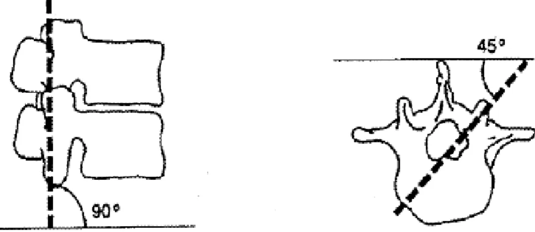
2.1.3. Facet Joint
The facet joint is composed of the superior articular process, inferior articular process, and joint capsule. The joint capsule attaches to the superior and inferior articular processes. The orientation of the facet joints varies with the spinal region. In general, the facets of the lumbar spine are oriented at a 90° angle to the transverse plane and at a 45° angle to the frontal plane (Figure 2.5). They stabilize the lumbar spine during compression, and prevent excessive axial
torsion and forward sliding between vertebrae [12].
2.1.4. Spinal Ligaments
A number of ligaments support the spine, including anterior longitudinal ligament (ALL), posterior longitudinal ligament (PLL), ligamentum flavum (LF), interspinous ligament (ISL), supraspinous ligament (SSL), intertransverse ligament (TL), and capsular ligament (CL). The orientation of each ligament is shown in Figure 2.2. The primary function of these ligaments is to protect the spine by preventing excessive movement. The amount of strain on the various ligaments differs with the type of motion of the spine. The capsular ligaments of the facet joints bear the most strain during axial torsion [13].
Figure 2.1: Vertebral column: anterior, left lateral and posterior views of the major regions of the spine.
Figure 2.2: The motion segment in the lumbar spine, which is composed of two vertebrae and the surrounding soft tissue [14].
(a)
(b)
Figure 2.3: The shape of a human vertebra. (a) Superior view of the typical lumbar vertebra. (b) The trabecular structure of a lumbar vertebral body in sagittal section [14].
Figure 2.4: The structure of an intervertebral disc. The disc consists of the nucleus pulposus (NP), annulus fibrosus (AF), and two cartilaginous vertebral endplates (VEP) [9].
Figure 2.5: The orientation of lumbar facet to the transverse plane (left) and the frontal plane (right).
2.2. Spinal Pathology and Treatments
The functions of the spine are to provide longitudinal weight support, limit excessive movement, and protect the posterior spinal cord. However, spinal instability may be induced by severe pathological changes, such as degenerative disc disease, spinal deformity, tumor, infection, trauma, congenital anomaly, inflammation, etc. (Figure 2.6). Thus, spinal nerve roots or the spinal cord may be compressed, leading to limb paralysis or low back pain (Figure 2.7). The first choice of treatment for low back pain is conservative therapy, such as physical therapy or medication. When conservative treatments fail, spine surgeons may perform either fusion or non-fusion surgery, with the aim of reducing pain and decreasing disability [15].
Figure 2.7: Magnetic resonance imaging (MRI) shows stenosis of the lumbar spine [17].
2.3. Spinal Fusion Techniques
The first report of spinal fusion was by Hibbs in 1911 [18]. Spinal fusion is defined as a bony union between two vertebrae spaces following surgical manipulation [19], and aims to completely eliminate movement by the motion segment (Figure 2.8). It is an effective technique for treating degenerative spinal instability, and the final goal of the procedure is to restore disc height, enlarge the stenotic foramen, and support the anterior spinal column. In general, bone grafts are placed into the interface between vertebral bodies to maintain disc height and to accelerate bone growth into neighboring vertebrae. These bone grafts may be autografts, allografts or synthetic materials which can be adopted from fibulae, illia, the iliac crest, or ribs.
Over the past 20 years, spinal fusion has become a very popular surgical technique for the treatment of low back pain caused by degenerative disc disorders. However, several of the complications of spinal fusion related to the use of bone grafts have been reported, such as high rate of graft collapse, spinal instability due to pseudarthrosis, deep infection at the donor site, and a low fusion rate using allografts [20]. Stauffer and Coventry [21] reported on 83 patients who had had an ALIF between 1959 and 1967. Only 36% of the 77 patients had good relief of pain for an average of 3.75 years of follow-up. In addition, the high rate of pseudarthrosis (44% of 68 patients) was evaluated radiographically at a minimum of 18 months’ follow-up. Dennis et al. [22] measured the height of disc space preoperatively, early postoperatively, and at an average of 29 months postoperatively in each of the 31 patients who had had an ALIF with the use of an autograft or allograft. Although immediate postoperative radiographs showed an average increase of 9.5 mm (89% of disc height preoperatively) in the disc height, the use of a graft alone did not provide long-term distension of the disc space or increase neuroforaminal height. Disc height decreased in every patient at 29 months after the ALIF operation. Thus, the nerve roots may be compressed again, leading to radiculopathy. These
studies demonstrated that the use of an autograft or allograft alone cannot deliver acceptable and satisfactory clinical outcomes in a long-term follow-up. To avoid the disadvantages of spinal fusion with the use of a bone graft alone, the spinal interbody fusion cage was developed to overcome these problems.
The most common surgical techniques for the insertion of a spinal cage can be classified as the ALIF approach, posterior lumbar interbody fusion (PLIF) approach, and transforaminal lumbar interbody fusion (TLIF) approach. In general, the ALIF approach includes the removal of the ALL, the anterior portions of the disc annulus, and the nucleus before implanting an interbody fusion cage (Figure 2.9; black arrow) [23]. For the PLIF approach, a partial laminectomy, discectomy and nucleotomy are performed, which includes the removal of the ISL, SSL, LF, posterior portions of the disc annulus, and the total nucleus. In addition, a certain portion of the facet joint can be removed to give the nerve roots more space (Figure 2.9; red arrow) [24]. Recently, the TLIF approach has been proposed and modified from the PLIF method to provide a minimally invasive surgical (MIS) technique. After the spine is approached, an inferior hemilaminectomy and a unilateral facectomy are performed (Figure 2.9; blue arrow) [25]. In general, the additional posterior fixation is suggested in order to reconstruct a stable environment. When the ALIF is combined with posterior fixation, the process is called an anterior-posterior (AP) fusion or a 360° fusion. The choice of surgical approach for insertion of a spinal cage is related to instability at the fusion site or the indication of each patient; however, it also depends on which approach the spine surgeon is most comfortable using.
2.3.1. Spinal Interbody Fusion Cage
The spinal interbody fusion cage was developed by Bagby in the 1980s. It can replace the degenerative disc and distension the intervertebral body, thus restoring physiological disc height.In general, there are several features of this device (Figure 2.10). First, the spinal fusion cage is made of a variety of
biocompatible materials, including stainless steel, titanium alloy, carbon fiber-reinforced polymer (CFRP), and polyetheretherketone (PEEK) [20]. Due to the high mechanical strength of these materials, a spinal interbody fusion cage can provide better longitudinal support than a traditional bone graft, without causing collapse. Second, rough or specific designs can be found on the contact surfaces of spinal cages. In order to prevent cage slippage, rough contact surfaces, saw teeth, spikes or threads have been designed to increase stability between fusion devices and endplates. Third, these implants are usually designed to be hollow, with small pore or openings on the wall. These hollow cages can be filled with bone grafts to promote bone growth. Furthermore, only small amounts of cancellous bone are required, because there is no longer need for the cubic graft to be a spacer. The small pores and openings on the wall allow the growth of bone through the cage, resulting in bony fusion. Therefore, spinal fusion cages can avoid donor site morbidity and increase fusion rates.
Currently, many kinds of spinal cage designs are available on the market (Figure 2.10), which can be classified by the various surgical approaches used in their implantation. Large single lumbar cage designs are used for the ALIF procedure (Figure 2.10 (c) and (d)). Some paired cage designs are used strictly for PLIF procedures (Figure 2.10 (e), (f), (g) and (h)), while others can be inserted using either an ALIF or PLIF (Figure 2.10 (a) and (b)). In addition, some specific shapes of cages are designed for MIS techniques such as the TLIF procedure (Figure 2.10 (i)). Despite differences among these cage designs, most cage designs are suggested for use in combination with posterior fixation. However, the stand-alone cage was developed for the ALIF procedure, removing the need for an additional posterior fixation system (Figure 2.10 (d)).
At present, ALIF combined with posterior pedicle screw fixation can provide better stability than other fusion techniques. Therefore, SynCage-Open interbody cage supplementation with posterior pedicle screw fixation was selected to represent the fusion model in this study.
2.3.2. Clinical Outcomes Associated with Fusion Cages
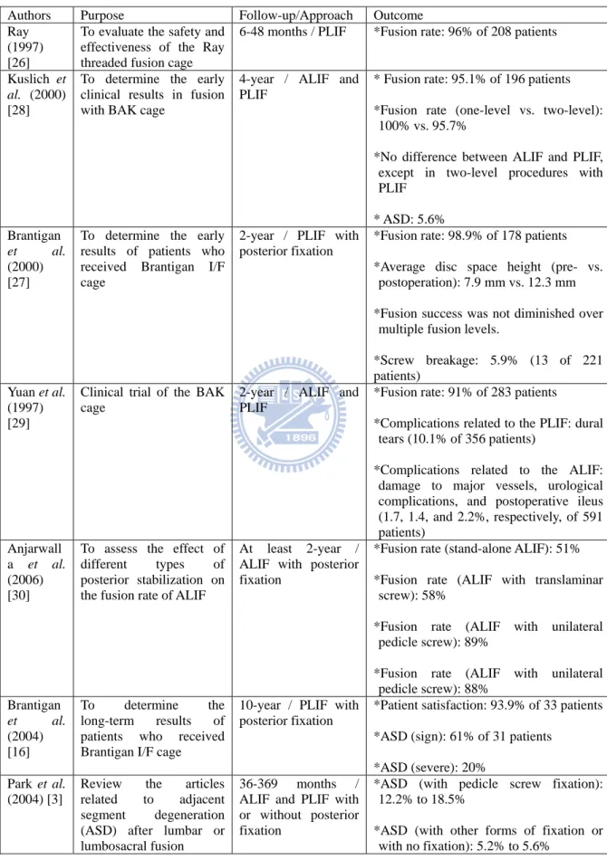
Previously reported clinical series of lumbar interbody fusion cages have demonstrated favorable short-term outcomes (Table 2.1), with the successful fusion rate ranging between 91% and 96% [26-29]. Brantigan et al. [27] indicated that use of a rectangular spinal cage can restore and maintain disc height at a 2-year follow-up. Kuslich et al. [28] reported the 4-year follow-up results of a BAK lumbar cage. The results indicated that the fusion rate was slightly better in the one-level procedure than in the two-level procedure (100% vs. 95.7%). Furthermore, there was little difference in the fusion rate between the ALIF and the PLIF for one-level procedures. However, in two-level procedures, the fusion rate was 68.4% (13/19) for the PLIF group. Yuan et al. [29] reported that the types and rates of complications differed between the ALIF and PLIF approach with the use of a threaded cage. In general, dural tears (10.1% of 356 patients) were only related to the PLIF approach, whereas damage to major vessels, urological complications, and postoperative ileus (1.7, 1.4, and 2.2%, respectively, of 591 patients) were associated with the ALIF approach. Overall, a spinal cage can maintain disc height, provide a high rate of fusion, be used in either one-level or two-level procedures, and obtain similar clinical results with both the ALIF and PLIF approaches.
The 10-year long-term results of spinal cage implantation have been reported by Brantigan et al. [16]. This study indicated that patient satisfaction was reached in 93.9% (31 of 37 patients) of patients. However, a high incidence of ASD was found. ASD occurred in 61% of patients, but was clinically significant in only 20%. Anjarwalla et al. [30] indicated that the use of pedicle screw stabilization with ALIF produced a significant increase in the rate of interbody fusion (from 51% up to 88%). Park et al. [3] reviewed reports in the literature of ASD disease after spinal fusion between 1966 and 2002, following the use of either a spinal cage or a bone graft. The incidence of ASD was higher
in patients with pedicle screw instrumentation (12.2–18.5%) compared to patients fused with other forms of instrumentation or with no instrumentation (5.2–5.6%).
In general, whether using a spinal cage or a bone graft, the long-term complications of ASD disease may be induced because various spinal fusions restrain motion at the surgical level [28, 31, 32]. Although the additional use of posterior pedicle screw instrumentation can increase the fusion rate [30], it also has been shown to increase the incidence of ASD disease (Figure 2.11) [3, 16, 33-35]. Clinical studies have reported incidence rates ranging from 5.2% to 61%, as shown in Table 2.1. Therefore, non-fusion spinal implants were developed to avoid ASD disease.
Figure 2.8: This radiograph demonstrates a solid bony union between L3 and L4 [27].
Figure 2.9: Common surgical techniques for insertion of a spinal cage. The black arrow indicates the ALIF approach, the red arrow indicates the PLIF approach, and the blue arrow indicates the TLIF approach.
(a) (b) (c)
(d) (e) (f)
(g) (h) (i)
Figure 2.10: Various lumbar interbody fusion cages: (a)TIBFD (Medtronic Sofamor-Danek, Inc., Memphis, Tennessee, USA); (b) BAK (Sulzer Spine-Tech Inc., Minneapolis, Minnesota, USA); (c) SynCage-Open (Synthes Spine, Inc., Mathys Medical Ltd., Bettlach, Switzerland); (d) SynFix (Synthes Spine, Inc., Mathys Medical Ltd., Bettlach, Switzerland); (e) posterior lumbar Brantigan I/F (Depuy-AcroMed Corp., Cleveland, Ohio, USA); (f) O.I.C. (Stryker Spine, Mahwah, New Jersey, USA); (g) Ray-TFC (Surgical Dynamics, Norwalk, Connecticut, USA); (h) Contact Fusion Cage (Stratec Medical Ltd., Oberdorf, Switzerland); (i) AVS-TL (Stryker Spine, Mahwah, New Jersey, USA).
Figure 2.11: Adjacent segment degeneration disease developed at L2/3 after 5-year spinal fusion [36].
Table 2.1: Clinical outcomes of lumbar interbody fusion cages
Authors Purpose Follow-up/Approach Outcome Ray
(1997) [26]
To evaluate the safety and effectiveness of the Ray threaded fusion cage
6-48 months / PLIF *Fusion rate: 96% of 208 patients Kuslich et
al. (2000) [28]
To determine the early clinical results in fusion with BAK cage
4-year / ALIF and PLIF
* Fusion rate: 95.1% of 196 patients *Fusion rate (one-level vs. two-level):
100% vs. 95.7%
*No difference between ALIF and PLIF, except in two-level procedures with PLIF * ASD: 5.6% Brantigan et al. (2000) [27]
To determine the early results of patients who received Brantigan I/F cage
2-year / PLIF with posterior fixation
*Fusion rate: 98.9% of 178 patients *Average disc space height (pre- vs.
postoperation): 7.9 mm vs. 12.3 mm *Fusion success was not diminished over
multiple fusion levels.
*Screw breakage: 5.9% (13 of 221 patients)
Yuan et al. (1997) [29]
Clinical trial of the BAK cage
2-year / ALIF and PLIF
*Fusion rate: 91% of 283 patients
*Complications related to the PLIF: dural tears (10.1% of 356 patients)
*Complications related to the ALIF: damage to major vessels, urological complications, and postoperative ileus (1.7, 1.4, and 2.2%, respectively, of 591 patients) Anjarwall a et al. (2006) [30]
To assess the effect of different types of posterior stabilization on the fusion rate of ALIF
At least 2-year / ALIF with posterior fixation
*Fusion rate (stand-alone ALIF): 51% *Fusion rate (ALIF with translaminar
screw): 58%
*Fusion rate (ALIF with unilateral pedicle screw): 89%
*Fusion rate (ALIF with unilateral pedicle screw): 88% Brantigan et al. (2004) [16] To determine the long-term results of patients who received Brantigan I/F cage
10-year / PLIF with posterior fixation
*Patient satisfaction: 93.9% of 33 patients *ASD (sign): 61% of 31 patients
*ASD (severe): 20% Park et al.
(2004) [3]
Review the articles related to adjacent segment degeneration (ASD) after lumbar or lumbosacral fusion
36-369 months / ALIF and PLIF with or without posterior fixation
*ASD (with pedicle screw fixation): 12.2% to 18.5%
*ASD (with other forms of fixation or with no fixation): 5.2% to 5.6%
2.4. Non-fusion Spinal Techniques
In contrast to fusion surgery, the concept of non-fusion surgery is to restore normal physiological motions, or to allow restrained motions within a certain range, through various mobile non-fusion devices that aim to avoid or alleviate ASD disease. Currently, there are several types of non-fusion devices that have been developed worldwide, such as artificial discs, nucleus prostheses, total facet arthroplasty systems, pedicle-based dynamic stabilization systems, and interspinous process spacers [37]. In general, most non-fusion devices are designed to either reconstruct the posterior elements (facet joints, ligaments) or replace only the nucleus pulposus. An artificial disc is the only device that is designed to replace all components of a degenerative disc and restore normal physiological motions. Therefore, an artificial disc was chosen for evaluation in this study.
There is no difference between the approaches used for fusion and non-fusion surgeries. The choice of surgical approach depends on which type of non-fusion devices is used. Pedicle-based dynamic stabilization systems, interspinous process spacers, and total facet arthroplasty systems are used strictly for posterior approaches, while nucleus prostheses can be inserted using either an anterior or posterior approach. Due to the size of an artificial disc, only the anterior approach is used to insertion an artificial disc.
The standard artificial disc replacement surgical procedure includes removal of the ALL, the anterior portions of disc annulus, and the complete nucleus pulposus. However, surgeons can consider resuturing the ALL to increase stability and preventing implant dislocation.
2.4.1. Artificial Disc
The first artificial disc designed to restore the motion and function was introduced by Weber [38] in 1978. This type of artificial disc was designed to replace the degenerative disc and to restore a normal physiological ROM. In
general, there are some features that can be found in all lumbar artificial discs (Figure 2.12). First, the artificial disc is always composed of two or more components. In fact, the most popular design for artificial discs is a metal-polymer-metal sandwich structure, which includes metallic endplates and a relatively soft polymer core [39]. The metallic endplate can be attached into the vertebral body to form an articulated surface which to place the central core. The core can be put between the superior and inferior metallic endplates, thus providing various degrees of movement and weight bearing. Second, one or more gliding contact interfaces provide either the semi-constrained or unconstrained movements to facilitate spinal mobility. Third, some special designs and a bioactive porous coating are used on the contact surface of the metallic endplate facing the vertebral body. The metallic endplate designs have spikes or serrations that are perpendicular to the surface to allow for fixation to the vertebral body. The surface coating can encourage bony ingrowth along the adjacent vertebral body [40].
A number of lumbar artificial discs are currently either commercially available or under clinical trial, and the most popular designs are shown in Figure 2.12. These artificial discs can be classified by either the material used for gliding interface or the type of motion allow by the disc [41, 42]. The materials used for gliding interfaces include metal-polymer (Figure 2.12 (a) and (b)) or metal-metal (Figure 2.12 (c) and (d)), as listed in Table 2.2. The type of motion allowed varies widely depending on the design. Some allow unconstrained motion (Figure 2.12 (a) and (e)), and others allow only constrained or semi-constrained motion (Figure 2.12 (b), (c), and (d)).
The primary example of an unconstrained artificial disc is the mobile core configuration of the SB Charité III, which theoretically allows 5 degree of freedom (three unconstrained rotations and two unconstrained translations) and aims to restore nearly physiological center of rotation (COR) (Figure 2.13 (a)). In contrast, the primary example of a semi-constrained artificial disc is the
ball-and-socket configuration of the ProDisc II, which theoretically allows 3 degree of freedom (three unconstrained rotations and three constrained translations) and aims to reduce anteroposterior shear forces on the facet joint (Figure 2.13 (b)).
Galbusera et al. [41] reviewed 96 studies and reported on the biomechanics of unconstrained and semi-constrained designs for artificial discs in the lumbar spine. They found that both designs of artificial disc mentioned here seem to be able to restore nearly physiological COR locations and ROM values. Segment lordosis is increased after a lumbar total disc replacement in most cases, for both semi-constrained and unconstrained designs. In addition, most studies described an increase in facet loads, for both semi-constrained and unconstrained artificial discs, but with some contrasting results. Semi-constrained designs may be able to share a greater part of the load, thus avoiding overload of the surrounding soft structures, and the associated risks of possible early degeneration.
At present, both SB Charité III and ProDisc II designs are popular; however, ProDisc II is much cheaper than SB Charité III, which confers an economic advantage. Therefore, ProDisc II disc arthroplasty was selected to represent the non-fusion model in this study.
2.4.2. Clinical Outcomes Associated with Artificial Discs
In a series of clinical reports, the outcomes of patients treated with artificial discs were excellent; the range of patient satisfaction was between 72% and 98% (Table 2.3). Delamater et al. [43] reported that disc replacement patients had significantly less pain and disability at 6 weeks postoperatively compared with those undergoing a 360° lumbar fusion. At 6 months postoperatively, no significant difference was found in pain and functional outcomes for both groups, but motion was significantly improved in the disc replacement group. Zigler et
al. [44] reported a 2-year follow-up of a prospective randomized FDA
device. The intraoperation data indicated that disc replacement patients had shorter operative times, shorter hospital stays, and less intraoperative blood loss as compared with those undergoing lumbar fusion. At the 3-month follow-up, the disc replacement group had a significantly greater improvement in functional outcomes than did the fusion group. Bertagnolo and Kumar [45] described a study of 108 patients with different indications for total disc replacement at 3 months to 2 years of follow-up. Of these patients, 98.2% reported good and excellent results, with only one complication. However, progression of disc degeneration at adjacent levels was noted in 10 patients. Overall, the early clinical outcomes of artificial disc replacement are better than those associated with 360° lumbar fusion in patient satisfaction rate, intraoperative status, and functional outcomes. Only a few cases of ASD disease were noted.
Recently, several studies have reported mid-term and long-term clinical results of artificial disc replacement. Siept et al. [46] reported that multi-level disc replacement had a significantly higher complication rate and lower satisfaction rate at a 3-year follow-up. Less than 5% of patients had ASD or facet joint problems. Shim et al. [47] reported that clinical outcomes of both ProDisc and Charité groups were good at a 3-year follow-up, although unexpectedly high rates of facet joint degeneration at the surgical level and disc degeneration at the adjacent level were identified. Improvement rates and degeneration rates did not significantly differ between ProDisc and Charité. Marnay [48] indicated that 92.7% of patients were satisfied with the use of a ProDisc I artificial disc at 7-11 years long-term follow-up. Huang et al. [49] reported the results of an 8.7-year follow-up to evaluate the relationship between ROM and ASD disease after a lumbar total disc replacement. The overall prevalence of ASD was 24%, but was higher in patients with ROM of less than 5° (34%) (Figure 2.14). Although a high incidence of ASD was found, ASD had no statistically significant effect on clinical outcome. Guyer et al. [50] reported the only mid-term clinical results of artificial disc replacement versus anterior
fusion related to ASD disease. No statistical differences were found in clinical outcomes between disc replacement and fusion patients. However, fusion patients reached a statistically higher rate of long-term ASD disease, as compared with disc replacement patients.
In general, mid- or long-term follow-up studies show high patient satisfaction rates and good clinical outcomes associated with the use of either ProDisc or Charité artificial disc replacements [47-49, 46, 50]. Patient satisfaction rates may decrease due to multi-level disc replacement. In addition, a remarkably high incidence of ASD disease and facet joint degeneration at the surgical level were found in some reports [47, 49]; however, contrasting results were also reported [46, 48, 50]. Therefore, long-term complications of ASD and facet joint degeneration after using artificial discs remain unconfirmed, and require further research.
(a) (b) (c)
(d) (e)
Figure 2.12: Various lumbar artificial discs: (a) SB Charité III (Depuy Spine, Inc., Raynham, Massachusetts, USA); (b) ProDisc II (Synthes, Inc., Paoli, Pennsylvania, USA/ Spine Solution, New York, USA); (c) Maverick (Medtronic Sofamor-Danek, Inc., Memphis, Tennessee, USA); (d) FlexiCore (Stryker Spine, Allendale, New Jersey, USA/ SpineCore, Inc., Summit, New Jersey); (e) AcroFlex (Depuy Spine, Inc., Raynham, Massachusetts, USA).
(a) (b)
Figure 2.13: Subcategories of artificial discs for motion include: (a) unconstrained design; (b) semi-constrained design [42].
Figure 2.14: Adjacent segment degeneration after total disc replacement [49].
Table 2.2: Classification of lumbar artificial disc [51, 52]
Type Material Articulating Interface Joint Motion type COR SB Charité
III
CoCrMo UHMWPE
Metal on Polymer 2 Unconstrained Mobile ProDisc II CoCrMo
UHMWPE
Metal on Polymer 1 Semi-constrained Fixed Maverick CoCrMo Metal on Metal 1 Semi-constrained Fixed FlexiCore CoCrMo Metal on Metal 1 Fully Constrained Fixed AcroFlex Ti-6AL-4V
Rubber
Metal bound rubber (Elastomeric)
Table 2.3: Clinical outcomes of artificial disc
Authors Purpose Follow-up / Type of Artificial Disc Outcome Delamater et al. (2003) [43]
To evaluate early pain and functional outcomes of patients treated with disc replacement or fusion
6-month / ProDisc II
*Disc replacement patients reported earlier improvement in pain and function than did the fusion patients (6 weeks); however, there was non difference at 6 months.
Zigler (2003) [44]
To compare the disc replacement and lumbar fusion in a prospective randomized FDA investigational study.
2-year / ProDisc II
*Total disc replacement was associated with less blood loss, reduced operative time, and reduced length of hospital stay compared to combined with anterior-posterior lumbar fusion. Bertagnolo and Kumar (2002) [45]
To find clinical outcome of patients treated with ProDisc II for various indications.
3-month to 2-year
/ ProDisc II
*Overall clinical outcome: 98.2% of 108 patients
* ASD: 10 of 108 patients Siept et al.
(2006) [46]
Mid-term clinical results of total lumbar disc replacement for different indications.
3-year / ProDisc II
* Satisfaction rate: 82.6% of 92 patients *Satisfaction rate (one-level vs. two-level):
85.7% vs. 64.3%
*ASD (Severe): 2.2% of 92 patients *Facet joint problems: 2.2% of 92 patients Shim et al.
(2007) [47]
To evaluate and compard clinicaland radiologic outcomes of the ProDisc and Charité.
3-year
/ ProDisc II or Charité III
*Clinical success rate (ProDisc vs. Charité): 83.3% (20 of 24 patients) vs. 93.9% (31 of 33 patients)
*ASD (ProDisc vs. Charité): 28.6% (6 of 21 segments) vs. 19.4% (6 of 31 segments) *Facet joint degeneration at the surgical level
(ProDisc vs. Charité): 32% (8 of 25 segments) vs. 36.4% (12 of 33 segments) *The degeneration rates of facet joints and
disc at adjacent level between two groups were not significantly different.
Marnay et al. (2002) [48]
Long-term results of the ProDisc
7-11 years / ProDisc I
*Satisfaction rate: 92.7% of 55 patients. *There was no evidence of subsidence or
migration. Huang et al. (2006) [49] To determine the relationship between range of motion (ROM) and adjacent segment degeneration (ASD)
8.7-year / ProDisc II
*ASD: 24% of 42 patients
*Patients with motion less than 5 ° (29 patients) had a 34% prevalence of ASD. *ASD had no statistically significant effect on
clinical outcome. Guyer et
al. (2009) [50]
To compare mid-term clinical results of lumbar disc replacement using Charité versus anterior lumbar interbody fusion using BAK cage.
5-years / Charité III
*Satisfaction rate (Charité vs. BAK): 78% (90 patients) vs. 72% (43 patients)
*Disc height: similar for both groups
*ASD (Charité vs. BAK): 8% (90 patients) vs. 20.9% (43 patients)
2.5. Development of Spinal Testing Protocols
Clinical reports have demonstrated long-term complications of ASD disease induced by spinal fusion surgery. The reasons for this disease may be explained by the concentration of stress and redistribution of motion along the spine after implanting various fusion devices. Therefore, many biomechanical studies have been undertaken to evaluate adjacent level effects (ALEs) of lumbar spines through ROM, intradiscal pressure, facet joint loading, or stress analysis to predict ASD disease in its early stages. However, conflicting results were found in these studies: increases in ALEs [53-59], no significant difference in ALEs [60-64], and decreases in ALEs [56, 57] have all been reported by several research groups. These inconsistent results may be due to differing testing protocols used to evaluate ALEs.
At present, several spinal testing protocols have been reported and used to predict ALEs, such as the LCM, the displacement control method (DCM), and a new HCM. However, it is still not clear which testing method is more suitable for revealing the physical effects of spinal implants. The following sections will introduce and review the results of these testing protocols in evaluating ALEs after simulating spinal fusion surgery.
2.5.1. Load Control Method
The load control testing method, also called the flexibility testing method, was proposed by Panjabi over three decades ago to be used for spinal testing [65]. This loading method applies the same pure moment to all spinal constructs, and then calculates the motions in each level. A pure moment is produced by applying two parallel forces, equal in magnitude, opposite in direction, and separated by a distance. The pure moment has two advantages. First, the pure moment applied to the end-vertebrae is applied equally to all the segments of the specimen. Second, the pure moment remains the same as the spine deforms during testing [66]. In general, the moment may range from 6 to 10 N-m for the
lumbar test [67]. In addition, a low compressive preload (100-200 N) was sometimes applied to the specimen in order to tighten and stabilize the spinal implant between two vertebrae.
Several biomechanical studies have attempted to evaluate ALEs after simulating lumbar spinal fusion by using the LCM [53-55, 60-64]. Cunningham
et al. [53] compared the adjacent level kinematics of total disc arthroplasty
versus conventional fusion fixation using five-level cadaveric lumbosacral spines. The results indicated that ALEs were markedly increased in both groups, including the BAK cage and the BAK cage combined with pedicle screws, under all physiological motions. Rao et al. [55] evaluated anterior cages in a calf lumbar spine model. The results showed that a small to moderate increase in motion was found at both adjacent levels in flexion and lateral bending. Intradiscal pressure changes at the inferior adjacent level were not significant. Sudo et al. [54] used ten calf spinal (L3-S1) specimens to evaluate five different lumbar reconstruction techniques on adjacent-level intradiscal pressure. They were unable to detect any difference in ALEs in their model of one-level posterior lumbar interbody fusion combined with pedicle screw fixation. However, a two-level fusion procedure significantly increased adjacent intradiscal pressure compared to the one-level fusion procedure. Rohlmann et al. [62] evaluated ALEs in ROM and intradiscal pressure at the levels above and below the internal fixator with use of the five-level cadaveric lumbosacral spines. The results indicated that using an internal fixation device on a spine specimen greatly affects intradiscal pressure changes and ROM at the surgical level. However, in most cases, ALEs in ROM and intradiscal pressure were small when load-controlled moments were applied. Similar results were also reported by Schmoelz [61, 64]. Rohlmann et al. [63] attempted to determine the influence of fixator stiffness on stresses in adjacent discs using FE analysis. Results showed that the maximum change of the von Mises stresses in the adjacent level discs was less than 10% when compared with the maximum value. Therefore,
they concluded that the stiffness of an internal spinal fixation device has only a minor influence on stresses in the adjacent discs.
In summary, the use of the LCM in evaluating stability of the whole lumbar spinal structure or the surgical level has been accepted, and stabilizing characteristics can be found [53-55, 60-64]. Although a number of studies revealed that the ALEs are greatly increased, or exhibit small to moderate increases with use of the LCM [53-55], most studies can not compute ALEs significantly when using only this testing protocol (Table 2.4).
2.5.2. Displacement Control Method
The displacement control testing method, also called the stiffness testing method, applies the same rotation-input to the spinal constructs, and then obtains the load-output behavior. There are several practical difficulties involved in using this method, especially for long spine with many segments [66, 68]. First, an axis of rotation must be defined before applying the rotation. However, the ideal location of the axis of rotation is not known prior to the first test, and different locations may be defined due to different experimental apparatus, manipulators, or specimens used. In addition, there is significant variability in the load-displacement curves, related to the location of the axis of rotation [69]. Therefore, the ideal axis of rotation is difficult to reproduce. Second, the ideal axis of rotation is cannot remain in the same location during the entire test, due to non-linear deformations of the spine. Third, if the axis of rotation is not in the ideal location, then spinal motions will be constrained, and can cause injury to the specimen. Fourth, the ideal axis of rotation will change after implanting various spinal implants. Beause of these disadvantages, the DCM is not often used to evaluate spine biomechanics like the LCM. In general, the rotation angle may range within physiological motion parameters, from 10° to 20° under flexion, and 5° to 15° under extension for the lumbar test (Table 2.5). Similar to the LCM, a 100~200 N compressive preload may be applied.
Several studies have used the DCM to evaluate ALEs after implanting various lumbar spinal fusion devices, and results are listed in Table 2.5 [56-59]. Shono et al. [57] used eighteen calf lumbosacral spine (L3-Sacrum) specimens to evaluate four posterior instrumentation systems in ROM changes at the both the surgical and adjacent levels. As segmental spinal instrumentation progresses from one level to three levels, the stiffness of the system significantly increases. However, ALEs were only detected at the upper level when using the Isola fixation system. In addition, ALEs decreased when using the Cotrel-Dubousset (CD) fixation system. Chow et al. [56] evaluated ALEs in ROM and intradiscal pressure at the levels above and below the fusion site with the use of six L1-S3 cadaveric lumbosacral spine specimens. The results indicated that fusion greatly affects ROM at both adjacent levels in flexion but not in extension. The intradiscal pressures of all unfused discs were only minorly increased in both flexion and extension, and the differences are within 5%. Cunninghum et al. [58] used 11 lumbosacral human cadaveric spinal specimens (T10-Sacrum) to evaluate changes in intradiscal pressures at adjacent levels under conditions of spinal reconstruction. In the instrumentation groups, disc pressure at the upper level increased by as much as 45%, whereas disc pressure at the surgical level decreased by between 41-55%.
In summary, stiffness of instrumentation can be evaluated in most biomechanical studies by using the DCM [56-58]. The DCM seems to be a better method for predicting ALEs due to the large increases of ROM and intradiscal pressure that were revealed, as compared with the LCM [56-59]. However, there is large variation in the reported ALEs, and results are conflicting between studies; increases in flexion [56-57, 59], increases in both flexion and extension [58], decreases in extension [56], decreases in both flexion and extension [57], and small changes [56] have all been independently reported (Table 2.5). Therefore, the DCM is not a proper method for revealing ALEs.
2.5.3. Hybrid Control Method
The HCM was first introduced by Panjabi in 2002 [70]. This approach applies different pure moments to each of the spinal constructs, and then the same overall ROMs are achieved for both intact and implant models. A detailed description of this method was presented in 2007 [66]. The four steps of the HCM are described in detail below.
(1) The specimen and its preparation: in order to reveal characteristics of motion redistribution, the whole mobile region should be tested. Therefore, the specimen of a T12-S1 long segment is recommended for in vitro testing. (2) The intact spine test: the traditional LCM is used for testing the intact
lumbar spine, and the specimens should not incur injury during the test. Then, the total ROM of the intact lumbar spine is measured.
(3) The spinal construct test: the spinal construct (specimen with a fusion and/or a non-fusion device) is subjected to increasing pure unstrained moments until the total ROM of the construct equals the ROM of the intact spine measured with the LCM (step 2).
(4) Data analysis: in order to evaluate ALEs, the increase in ROM or other biomechanical parameters at a non-operated spinal level is measured.
Goel et al. [71] indicated that, in real life, people bend their spines within a similar, limited ROM regardless of whether their spine is healthy or has undergone spinal surgery. In addition, the patient’s main aim following surgery is to return to normal daily life. Thus, the surgically treated spine should be able to go through the same ROM as in a normal person. Therefore, they suggested that the spinal construct should be tested under the same ROM and the HCM should be more clinically relevant.
Currently, a number of studies have evaluated spinal implant biomechanics using the HCM [66, 71-73]. However, only one study has focused on the differences between the LCM and HCM. Goel et al. [71] analyzed ALEs of artificial discs that used both the LCM and the HCM, and revealed that ALEs
were not obvious under the LCM, while the ALEs (in this case, decreased ROM) were obvious under the HCM. It is still not clear whether the LCM or the HCM is more suitable to reveal the physical effects of spinal implants. Therefore, current study used FE analysis with both the LCM and HCM to explore biomechanical differences, at the implant level and at adjacent levels, between anterior fusion and non-fusion spinal implants.
Table 2.4: Adjacent level effects of lumbar spines were evaluated in flexion and extension under the load control method.
Increase in ROM normalized to intact (%)
Upper level Lower level
Author Fusion level ;
Fusion device
Flexion Extension Flexion Extension
Applied moment (Nm) Cunningham et al. (2003) [53] L4-L5 ; BAK+Isola fixation 11 20 8 Schmoelz et al. (2003) [64] L3-L4 ; Fixator NS NS NS NS 10 Rao et al. (2006) [55] L3-L4 ; LT-Cage 12.5 NS 11.3 NS 8.5 Rohlmann et al. (2001) [62] L2-L4 ; Fixator S NS S NS 3.75
Increase in intradiscal pressure normalized to intact (%) Schmoelz et al. (2006) [61] L3-L4 ; Fixator < 5 (NS) < -10 (NS) - - 10 Rao et al. (2006) [55] L3-L4 ; LT-Cage 21 -16 (NS) 10 -5 (NS) 8.5 Sudo et al. (2006) [54] L5-S1 ; Brantigan cage+Isola fixation 80 (S) 60 (S) - - 6 Rohlmann et al. (2001) [62] L2-L4 ; Fixator NS S S NS 3.75
Table 2.5: Adjacent level effects of lumbar spines were evaluated in flexion and extension under the displacement control method.
Increase in ROM normalized to intact (%)
Upper level Lower level
Author Fusion level ;
Fusion device
Flexion Extension Flexion Extension
Applied displacement (degrees) Shono et al. (1998) [57] L4/5 (one-level fusion) L4/L6 (two-level fusion) ; Isola fixation L4/5 (one-level fusion) L4-L6 (two-level fusion) ; CD 20 35 -48 -12 -8 -50 -8 -42 7.4 flexion 5 extension Chow et al. (1996) [56] L4/5; Bone cement (ALIF) 240 -9 169 -25 15 flexion 10 extension Increase in intradiscal pressure normalized to
intact (%) Chow et al. (1996) [56] L4/5 ; Bone cement (ALIF) 5 5 4 2 15 flexion 10 extension Cunningham et al. (1997) [58] L3/4 ; Pedicle screw fixation L3/L4 ; Isola fixation 30 25 45 35 17.5 10 40 35 12.5 flexion 12.5 extension Weinhoffer et al. (1995) [59] L5/S1 ; Pedicle screw fixation 30 - - - 20 flexion
2.6. In Vitro Test versus Finite Element Simulation
In vitro cadaveric tests and FE analyses are often used to assess the function
of spinal implants, assess different surgical treatment scenarios, and predict short- or long-term pathological change before in vivo animal studies and clinical trials. The characteristics of in vitro tests are described below. First, the data are based on real test cases. Thus, the response of the neutral zone (the stiffness characterizing the lax deformation of the specimen) can be obtained. Second, the maximum failure load of the spinal construct can be obtained. However, there are some disadvantages. First, human cadaveric specimens are not easy to obtain in Taiwan. If animal specimens are used, the study is complicated by the large differences between humans and animals. Second, tests are time consuming and expensive. Third, large variances are found between specimens, which are related to age, aging, bone mineral density, or other factors. Fouth, it is not easy to overcome the drawbacks of measurement force and stress distribution on the soft tissue. Therefore, most in vitro studies still focus on the motion behavior of the lumbar spine.
There has been a rapid rise in the use of FE analysis to address the disadvantages of in vitro tests over the last decade [74-75]. FE analysis has several advantages. First, in an FE model, it is easy to modify geometry and material properties and assist in the design and development of the spinal implant. Second, stress distribution in each spinal structure can be revealed to understand how stress is redistributed after surgery. Third, it is easy to apply various testing protocols and loading cases to mimic different physiological conditions. The disadvantages of FE analysis are mentioned below. First, FE simulations will not indicate any unreasonable results. Therefore, engineers should independently judge the rationality of simulation results. Second, a convergence test and model validation must be executed before interpreting the data. However, it is difficult to validate a biomedical FE model due to the highly variable quality of cadaveric specimens. Therefore, discrepancies between in
vitro tests and FE simulations always exist. Third, it is not easy to obtain real
material properties of spine. Lastly, there are some simplification and assumptions inherent in the FE model.

![Figure 2.2: The motion segment in the lumbar spine, which is composed of two vertebrae and the surrounding soft tissue [14]](https://thumb-ap.123doks.com/thumbv2/9libinfo/8459566.183118/22.892.244.699.218.587/figure-motion-segment-lumbar-composed-vertebrae-surrounding-tissue.webp)
![Figure 2.4: The structure of an intervertebral disc. The disc consists of the nucleus pulposus (NP), annulus fibrosus (AF), and two cartilaginous vertebral endplates (VEP) [9]](https://thumb-ap.123doks.com/thumbv2/9libinfo/8459566.183118/24.892.295.640.213.668/structure-intervertebral-consists-pulposus-fibrosus-cartilaginous-vertebral-endplates.webp)
![Figure 2.7: Magnetic resonance imaging (MRI) shows stenosis of the lumbar spine [17]](https://thumb-ap.123doks.com/thumbv2/9libinfo/8459566.183118/27.892.318.619.211.682/figure-magnetic-resonance-imaging-shows-stenosis-lumbar-spine.webp)
![Figure 2.8: This radiograph demonstrates a solid bony union between L3 and L4 [27].](https://thumb-ap.123doks.com/thumbv2/9libinfo/8459566.183118/32.892.288.648.536.1060/figure-radiograph-demonstrates-solid-bony-union-l-l.webp)

![Figure 2.11: Adjacent segment degeneration disease developed at L2/3 after 5-year spinal fusion [36]](https://thumb-ap.123doks.com/thumbv2/9libinfo/8459566.183118/35.892.352.620.208.647/figure-adjacent-segment-degeneration-disease-developed-spinal-fusion.webp)
![Figure 2.13: Subcategories of artificial discs for motion include: (a) unconstrained design; (b) semi-constrained design [42]](https://thumb-ap.123doks.com/thumbv2/9libinfo/8459566.183118/43.892.137.808.106.414/figure-subcategories-artificial-motion-include-unconstrained-design-constrained.webp)
