AN APPLICATION OF BOREHOLE ACOUSTIC
TELEVIEWER AND DOUBLE PACKER SYSTEM TO
THE STUDY OF HYDRAULIC PROPERTIES OF
FRACTURED ROCKS: A CASE STUDY IN
KAOHSIUNG, TAIWAN
Shih-Meng Hsu, M. C. Chung, C. Y. Ku, C. H. Tan
Geotechnical Engineering Research Center, Sinotech Engineering Consultants, Inc., Taipei, Taiwan
M. C. Weng
Department of Civil and Environmental Engineering, National University of Kaohsiung, Taiwan
ABSTRACT
This paper presents a study on the hydraulic properties of fractured rocks using a borehole acoustic televiewer and double packer system. Two deep boreholes located in Kaohsuing, Taiwan were tested in this study. The paper characterizes the hydraulic properties for the two test sites and concludes that infillings, lithology, and interconnectivity of fractures are significant factors affecting the hydraulic properties of fractured rocks. The borehole-geophysical logging from the televiewer was proven to be a highly efficient way to obtain useful information (eg. positions of geological structures and fractures) for hydraulic testing during hydrological investigations.
RÉSUMÉ
Cet article présente une investigation des propriétés hydrauliques des pierres fracturées, se servant une sonde acoustique télévisuelle de forage et un système à double packer. Deux puits profonds forés en Kaohsiung, Taiwan, ont été examinés au cours de ces recherches. Cet article caractérise les propriétés hydrauliques des deux sites, et en conclue que les remplissages, la lithologie, et l’interconnexion des fractures, sont des facteurs importants qui déterminent les propriétés hydrauliques des pierres fracturées. Il est démontré que l’enregistrement géophysique du télévisuelle est un moyen efficace d’obtenir de renseignements utiles (par exemple, sur la position de structures géologiques et de fractures), au cours des investigations hydrologiques.
1 INTRODUCTION
The use of geophysical survey methods in hydrogeology is increasing and is widely being applied to the evaluation of aquifer geometry and the determination of the subsurface hydraulic parameters (Singhal et al. 1999). For instance, borehole acoustic televiewers (BHTV) can be used to identify lithology and fractures in open boreholes instead of visual logging of core samples. The image data not only indicate the exact depths of fractures, but also bring information to arrange test sections of hydraulic tests. BHTV logs in combination with a double packer system (DPS) can be integrated as a survey method to determine hydraulic parameters.
Currently, implementing both tools during an investigation of hydraulic properties of fractured rocks is not common in Taiwan. The objective of this paper is to present such an application in a transbasin diversion tunnel project in Kaohsiung, Taiwan. The BHTV results provided valuable information during the design of the hydraulic tests by
allowing more accurate depth interpretations of geological structures and fractures compared to traditional rock core interpretations. The hydraulic tests using DPS were performed in two deep boreholes (250m and 350 m in depth) to determine the hydraulic properties of fractured rocks intersecting the two boreholes. The main hydraulic testing strategy was to detect water-bearing zones and to investigate the vertical variation of the hydraulic conductivity in a borehole and hydraulic properties of fault-related rocks. Results from the test therefore can greatly help characterize part of the hydraulic properties for the tunnel site.
2 TESTING TOOLS
2.1 Borehole Acoustic Televiewer
A high-resolution borehole acoustic televiewer was used during the study. The borehole televiewer probe uses a fixed acoustic transducer and rotating acoustic mirror to scan the borehole walls with a focused ultrasound beam.
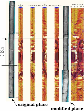
The amplitude and travel time of the reflected acoustic signal are recorded simultaneously as separate image logs. According to the results, geologic features such as fractures, voids, foliation, and layering can be identified. This type of downhole logging is continuous and competitive with traditional borehole exploration in interpretation of rock samples because these investigated data are not affected by human mistakes or do not contain missing intervals. Figure 1 shows the position of rock core was misplaced by drillers from its original place (The difference between the original place and modified place is 0.85 m). This mistake would result in incorrect borehole exploration at the exact depths. In order to gain accurate geological data of the borehole wall without human errors, the research group selected the tool during the design of hydraulic tests.
Figure 1. Comparison of acoustic image data and traditional rock core in borehole HB-95-01 at the depth of 133.2-136.1 m
2.2 Double Packer System
Double packer systems (DPS) are the most commonly used tools for hydrogeological testing in boreholes (Singhal et al. 1999; NRC 1996). They can be used to determine the hydraulic conductivity in a section of borehole using two inflatable packers. It is now recognized that this approach is applicable for
investigating the variability of a borehole as it intersects various hydrogeological units (Singhal et al. 1999; NRC 1996).
The double packer system in this study as shown in Figure 2 consists of two inflatable rubber packers, a shut-in valve, a submersible pump, and pressure transducers for monitoring areas above and below the packers and the isolated interval. The shut-in valve can open or close the hydraulic connection between the pipe string and the test section. The rubber packers can be inflated using nitrogen delivered through a polyethylene air line. The pumping or injecting rate can be monitored at the land surface with a flow meter. To conduct each hydraulic test, the packers are inflated to isolate a section of borehole, and the rate of flow and/or pressure in the test interval over a period of time can be measured.
In addition, four types of tests, including pumping tests, injection tests, slug tests, and pressure pulse tests can be applied to the double packer system. Pumping tests involve pumping at a constant or variable rate and measuring changes in water levels during pumping. In injection tests, fluid is injected into a test interval while keeping the head of the test interval at a constant value. A slug test involves the abrupt removal, addition, or displacement of a known volume of water and the subsequent monitoring of changes in water level as equilibrium conditions return. In a pressure pulse test, an increment of pressure is applied to a packed zone. The pressure decay is monitored. Typically, the decision on which type of test to perform is based on the expected permeability of the test interval, the volume of rock to be sampled, and the availability of time and equipment (NRC 1996). Hydraulic properties determined by slug tests or pressure pulse tests are representative only for the material in the immediate vicinity of the borehole.
To obtain hydraulic conductivity over a large area, the procedure of a single-hole hydraulic test is to perform a pumping test at a test interval first. If the pumping test cannot be performed due to low permeability of the test section, a constant head injection test will be conducted instead. Once the flow rate cannot be measured by limitation of the flow meter (less than 0.11l/min) during the injection test, a slug test or pressure pulse test can be performed. The duration of a pressure pulse test is much shorter than that of a slug test. For this reason, the pressure pulse test is commonly applied to test intervals of very low permeability. However, the volume of rock tested by a pressure pulse test is significantly smaller compared to a slug test.
3 CASE STUDY
3.1 Description of Study Area
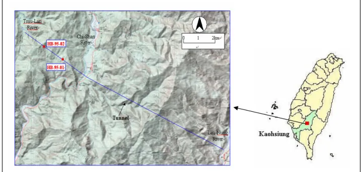
Figure 3 shows locations of the study area, boreholes, and Tseng-Wen transbasin diversion tunnel. The study area is located at Shang-Ming, Kaohsiung County, south of Taiwan. The tunnel was designed as a transbasin
diversion tunnel of Tseng-Wen reservoir for complementing water supply in southern Taiwan. During flood seasons, the surplus water of the Lau-Nung River, a tributary of the Gao-Ping River, is transported into the Tseng-Wen reservoir through the tunnel for allocation and storage. After the project completion, it is expected to increase 0.6 million tons of supply water daily to meet the future demand for the south area.
Boreholes HB-95-01 and HB-95-02 were newly drilled boreholes. They superseded two previous groundwater-monitoring wells that malfunctioned in September 2005. The lengths of boreholes HB-95-01 and HB-95-02 are 250m and 350m, respectively. The principal lithologic units for HB-95-01 are sandstone, argillaceous sandstone, and sandy mudstone. The principal lithologic units for HB-95-02 are sandstone, argillaceous sandstone, and sandstone mixed with some mudstone. Boreholes HB-95-01 and HB-95-02 are close to the Biauhu fault and Pingshi fault, respectively. Rock core data indicated soft and cohesive gouges are extensive in both boreholes. This provided a good opportunity to study hydraulic properties of fault-related rocks as well.
Figure 3. Locations of the study area, boreholes, and Tseng-Wen transbasin diversion tunnel 3.2 Hydraulic Test Design
Prior to hydraulic testing, the study utilized the high-resolution borehole acoustic televiewer to scan images of HB-95-01 and HB-95-02. The information gathered from the BHTV was used to characterize lithology and fractures for the two boreholes and was essential for the design of the hydrogeological program.
Understanding of whether a zone of high permeability exists at the tunnel site is crucial to resolve safety issues. For a tunnel excavation project, the problem of water inflow during tunnel construction must be considered. For this reason, the main testing strategy in this study was to detect water-bearing fractures that could flood the tunnel. In addition, the study investigated the vertical variation of the hydraulic conductivity in a borehole and hydraulic property of fault-related rocks.
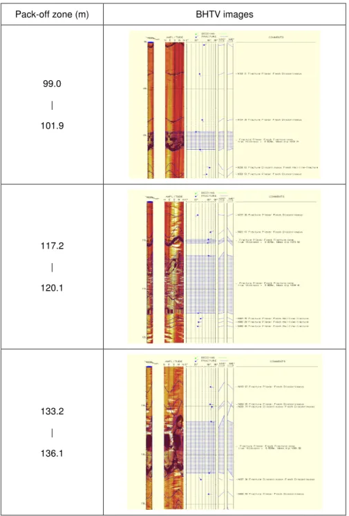
A subsurface water-bearing zone commonly appears in the section with multiple fractures. According to the BHTV logs from boreholes HB-95-01 and HB-95-02, the study selected locations with images that showed multiple fractures as hydraulic test sections. Figure 4 shows that three testing zones were selected by this strategy. Their corresponding BHTV images in borehole BH-95-01 are also shown in Figure 4.
A total of 16 hydraulic tests were designed to determine hydraulic conductivity in the two boreholes. Hydraulic
tests in borehole HB-95-01 were carried out in the intervals of 99.0-101.9 m, 117.2-120.1 m, 133.2-136.1 m. and 142.9-145.8 m. Hydraulic tests in borehole HB-95-02 were carried out in the intervals of 88.6-91.4 m, 96.0-99.2 m, 118.5-121.7 m, 134.8-138.0 m, 154.8-158.0 m, 173.0-176.2 m, 189.8-193.0 m, 196.6-199.8 m, 213.2-216.0 m, 249.0-251.8 m, 272.0-274.8 m, and 306.8-309.6 m.
Pack-off zone (m) BHTV images
99.0 | 101.9 117.2 | 120.1 133.2 | 136.1
3.3 Data Analysis
Data analysis involved mainly the transformation of raw field data into calculated values of hydraulic coefficients. Data collected during hydraulic tests can be analyzed by analytical methods. A number of hydraulic test analysis methods are available for various aquifers and can be found in textbooks (Kruseman and De Ridder 2000). A few models also take into account boundary effects such as wellbore storage and skin effects. When analyzing test data, various theoretical models can be applied. This process is repeated until a good match is attained between measured data and the simulation.
Water pressure and discharge rate measurements with time for each hydraulic test were collected in this study. The data analysis was performed using a professional version of the test analysis software AQTESOLVE, which enables both virtual and automatic type curve matching (Duffield 2004). The quantitative evaluation of hydraulic parameters was carried out as an iterative process of the best-fit theoretical response curves based on the measured data of the hydraulic test.
3.4 Results and Discussion
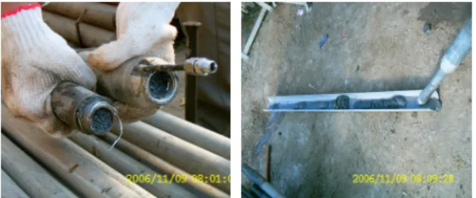
14 out of 16 hydraulic tests were successfully carried out. However, two hydraulic tests at the depth of 142.9-145.8 m in borehole HB-95-01 and at the depth of 306.8-309.6 m in borehole HB-95-02 failed. After investigation, such failures may be related to soft and cohesive gouges existing at the test intervals. Borehole walls at the test intervals may constrict. When packers were inflated, rock materials such as breccias and clay-rich gouges gradually filled in the tubes from the perforated tube between the upper packer and lower packer. Over a period of time, the pass-through tubes of the packers and the perforated tubes were infilled with the rock materials. Figure 5 shows the packer was infilled with breccias and clay-rich gouges. This situation resulted in the failure of the test.
Figure 5. Photographs of packer infilled with breccias and clay-rich gouges
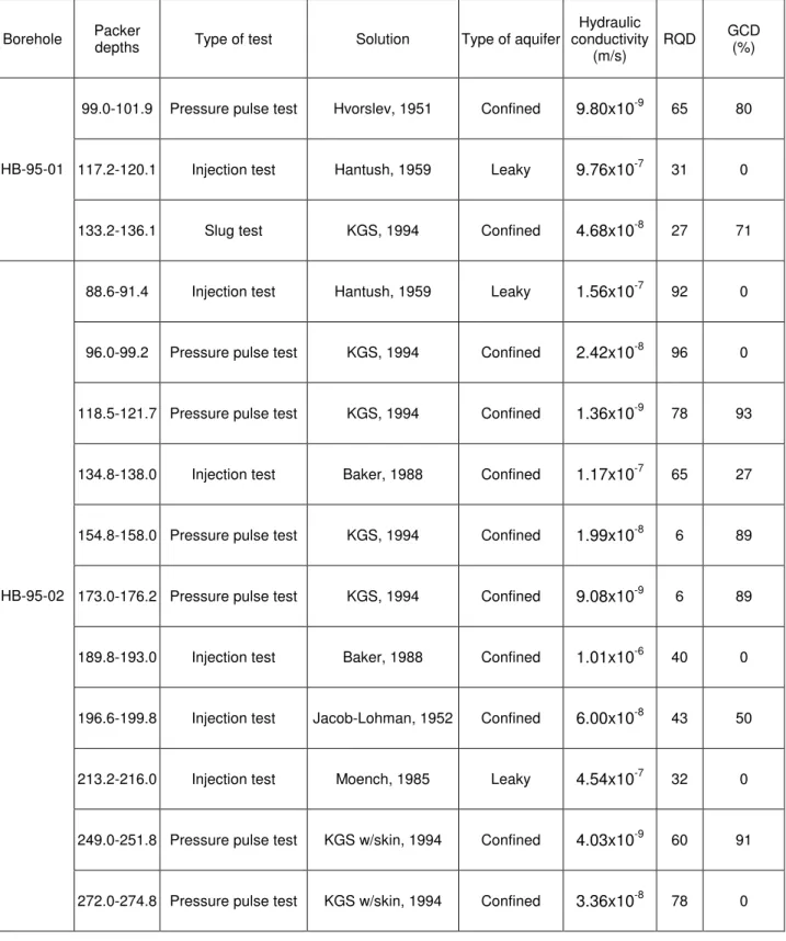
Table 1 summarizes the obtained hydraulic conductivity data from the results of the field hydraulic tests. Isolated borehole intervals, test types, aquifer types, solutions of hydraulic test analyses, and rock quality designation (RQD) and gouge content designation (GCD) for each
test interval are also listed in Table 1. The results of hydraulic tests in borehole HB-95-01 indicate hydraulic conductivity ranges from 9.76 x 10⁻⁷ m/s to 9.80 x 10⁻⁹ m/s with an average of 3.44 x 10⁻⁷ m/s from the available test results. A test interval at the depth of 117.2-120.1 m is more permeable than other intervals in borehole HB-95-01. Hydraulic conductivity for borehole HB-95-02 ranges from 1.01 x 10⁻⁶ m/s to 1.36 x 10⁻⁹ m/s with an
average of 1.72 x 10⁻⁷ m/s from the available test results. A tested zone at the depth of 189.8-193.0 m is more permeable than other intervals in borehole HB-95-02. Based on the concept of the best-fit theoretical response curves, different solutions of hydraulic test analyses were applied to determine hydraulic conductivity. According to the assumption of each solution, the aquifer type and boundary effect of the borehole wall can be identified as shown in Table 1.
In Table 1 constant head injection tests were only performed in more permeable intervals (e.g., greater than the order of 10-8 m/s). For test intervals of low
permeability, slug tests and pressure pulse tests were used to complete the hydrogeological investigation. In the testing program, pumping tests could not be used because they were very difficult to maintain a constant flow at any test intervals.
In Table 1, the RQD is defined as the cumulative length of core pieces longer than 100 mm in a run divided by the total length of the core run. A core run for calculating the RQD is herein defined as a selected zone of hydraulic tests. The RQD value was computed using the BHTV images directly. This provided preliminary information for placement of inflatable packers in hydraulic testing. Comparing the data of RQD and hydraulic conductivity in Table 1, it turned out that the decrease of the RQD value did not vary with the increase of hydraulic conductivity.
Since RQD doesn’t account for gouge material existing in fractures, this study defined a new index called gouge content designation (GCD) to correspond to fracture permeability. The GCD value is defined as a percentage of gouge content in a core run. This index can modify expected permeability based on the RQD value at a test interval. Comparing the data of RQD, GCD, and hydraulic conductivity in Table 1, it turned out that the degree of gouge content at a test interval would control the permeability of fractured rocks. If the fractures contain the gouge material, permeability of the fractures may reduce. This situation in a few of isolated borehole intervals has been observed.
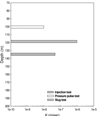
Figures 6 and 7 show hydraulic conductivity with depth for boreholes HB-95-01 and HB-95-02, respectively. Although rock mass permeability may vary systematically as a function of depth due to the effect of geostatic stresses (Lee 1993), a decrease in permeability with depth for both boreholes was not observed.
Table 1. Results of hydraulic tests in boreholes HB-95-01 and HB-95-02
Borehole Packer depths Type of test Solution Type of aquifer conductivity Hydraulic (m/s) RQD
GCD (%)
99.0-101.9 Pressure pulse test Hvorslev, 1951 Confined 9.80x10⁻⁹ 65 80
117.2-120.1 Injection test Hantush, 1959 Leaky 9.76x10⁻⁷ 31 0 HB-95-01
133.2-136.1 Slug test KGS, 1994 Confined 4.68x10⁻⁸ 27 71
88.6-91.4 Injection test Hantush, 1959 Leaky 1.56x10⁻⁷ 92 0
96.0-99.2 Pressure pulse test KGS, 1994 Confined 2.42x10⁻⁸ 96 0
118.5-121.7 Pressure pulse test KGS, 1994 Confined 1.36x10⁻⁹ 78 93
134.8-138.0 Injection test Baker, 1988 Confined 1.17x10⁻⁷ 65 27
154.8-158.0 Pressure pulse test KGS, 1994 Confined 1.99x10⁻⁸ 6 89
173.0-176.2 Pressure pulse test KGS, 1994 Confined 9.08x10⁻⁹ 6 89
189.8-193.0 Injection test Baker, 1988 Confined 1.01x10⁻⁶ 40 0
196.6-199.8 Injection test Jacob-Lohman, 1952 Confined 6.00x10⁻⁸ 43 50
213.2-216.0 Injection test Moench, 1985 Leaky 4.54x10⁻⁷ 32 0
249.0-251.8 Pressure pulse test KGS w/skin, 1994 Confined 4.03x10⁻⁹ 60 91 HB-95-02
K (m/sec)
1e-10 1e-9 1e-8 1e-7 1e-6 1e-5
D ep th ( m ) 70 80 90 100 110 120 130 140 150 160 170 180 190 200 Injection test Pressure pulse test Slug test
Figure 6. Hydraulic conductivity with depth for borehole HB-95-01
K (m/sec)
1e-10 1e-9 1e-8 1e-7 1e-6 1e-5
D ep th ( m ) 70 80 90 100 110 120 130 140 150 160 170 180 190 200 210 220 230 240 250 260 270 280 Injection test Pressure Pulse test
Figure 7. Hydraulic conductivity with depth for borehole HB-95-02
4 CONCLUSIONS
Rock cores from boreholes HB-95-01 and HB-95-02 can indicate the depth of fractures and distribution of lithology with depth. However, these data may be affected by misplacement of rock cores from drillers or contain missing intervals, especially in intensely fractured intervals that are of critical interest. This paper introduces a high-resolution acoustic televiewer for borehole exploration, which is not commonly adopted in Taiwan. This tool allows for quantitative and statistical measurements of the depth, thickness, and orientation of fractures. Since data from the equipment can quickly provide the exact depth of fractures, this can bring information to arrange test sections of hydraulic tests. This study integrated the borehole acoustic televiewer with a double packer tool on hydrogeological investigation. The borehole-geophysical logging from the borehole acoustic televiewer was proven to be a highly efficient way to obtain useful information for hydraulic testing, such as the location, strike, and dip of fractures, as well as the lithologic contacts. Thus, the BHTV preliminary information can assist in not only the proper design of the test but also the choice of a conceptual model for analyzing hydraulic test data.
This study observed that fracture connectivity and infillings cannot be identified using the borehole acoustic televiewer technique. This problem can be solved from interpretation of rock core samples or flowmeter logs. Hydraulic properties of fractured rocks have been studied by in situ hydraulic tests performed in two deep boreholes. Hydraulic conductivity in HB-95-01 was slightly greater than HB-95-02. Hydraulic conductivity with depth for both boreholes was presented as well. Results from the hydraulic tests characterized part of the hydraulic properties for the Tseng-Wen transbasin diversion tunnel site. This characterization of hydraulic properties is a critical step for modeling water inflow into the tunnel during excavation.
Hydraulic property of fault-related rocks has been studied. Results from the test data indicated that soft and low cohesion gouges existing in the fault-related rocks would definitely reduce the permeability of the fractured rocks. According to the hydraulic test results, permeability of fractured rocks with gouge materials would decrease one to two orders of magnitude.
ACKNOWLEDGEMENTS
The study was support by a grant from Southern Water Resources Office, Water Resources Agency, Ministry of Economic Affairs, Taiwan. The authors would like to acknowledge Mr. Ching-En Tseng for his constructive support on the hydraulic tests.
Baker, J.A. 1988. A generalized radial flow model for hydraulic tests in fractured rock, Water Resources
Research, 24(10): 1796-1804.
Duffield, G.M. 2004. AQTESOLVE version 4 user’s
guide, Developer of AQTESOLV HydroDOLVE, Inc.,
Reston, VA, USA.
Hantush, M.S. 1959. Nonsteady flow to flow wells in leaky aquifer, Journal of Geophysical Research, 64(5): 1043-1052.
Hvorslev, M.J. 1951. Time lag and soil permeability in
gound water observations, Bull, No. 36, Waterways
Exper. Sta. Corps of Engrs, U.S. Army, Vicksburg, Mississippi, USA.
Hyder, Z., Butler, J.J., Jr., McElwee, C.D. and Liu, W. 1994. Slug tests in partially penetrating wells, Water
Resources Research, 30(11): 2945-2957.
Jacob, C.E. and Lohman, S.W. 1952. Nonsteady flow to a well of constant drawdown in an extensive aquifer,
Trans. Am. Geophs. Union, 33:559-569
Kruseman, G.P. and De Ridder, N.A. 2000. Analysis and
evaluation of pumping test data, 2nd ed., ILRI
Publication 47, Wageningen, The Netherlands. Lee, C.H. and Farmer, I. 1993. Fluid flow in
discontinuous rocks, Chapman&Hall, London, UK.
Moench, A.F. 1985. Transient flow to a large-diameter well in an aquifer with storative semiconfining layers,
Water Resources Research, 21(8): 1121-1131.
National Research Council. 1996. Rock fractures and
fluid flow: contemporary understanding and
applications, National Academy Press, Washington
DC, USA.
Singhal, B.B.S. and Gupta, R.P. 1999. Applied
hydrogeology of fractured rocks, Kluwer Academic