國
立
交
通
大
學
多媒體工程研究所
碩 士 論 文
利用 3D KINECT 影像做視訊監控應用上之隱私
保護與秘密隱藏
Privacy Protection and Secret Hiding via 3D KINECT Images
for Video Surveillance Applications
研 究 生:曾頌賢
指導教授:蔡文祥 教授
利用立體 KINECT 影像做視訊監控應用上之隱私保護與秘密隱藏
Privacy Protection and Secret Hiding via 3D KINECT Images for Video
Surveillance Applications
研 究 生:曾頌賢 Student:Chung-Yin Tsang
指導教授:蔡文祥 Advisor:Wen-Hsiang Tsai
國 立 交 通 大 學
多 媒 體 工 程 研 究 所
碩 士 論 文
A ThesisSubmitted to Institute of Multimedia Engineering College of Computer Science
National Chiao Tung University in partial Fulfillment of the Requirements
for the Degree of Master
in
Computer Science
June 2013
Hsinchu, Taiwan, Republic of China
i
利用立體 KINECT 影像做視訊監控應用上之隱私保護與秘
密隱藏
研究生:
曾頌賢
指導教授: 蔡文祥
國立交通大學多媒體工程研究所
摘要
隨著立體電腦視覺技術的快速發展,3D 影像設備越來越普及,可在各種條 件下讀取 3D 多媒體資訊。微軟的 KINECT 設備即是一著名的例子,它不僅可以 捕捉彩色影像,更可以捕捉深度資訊,讓各種應用中的 3D 資訊擷取變得更為方 便。 本研究提出了三種方法來達到在 3D 視訊監控中保護隱私及進行 3D 影像偽 裝的目的。第一種方法可在 3D 視訊監控中保護使用者所選擇的隱私區域。該法 利用可逆的映射函式,將隱私區域的影像轉變為與背景影像相似的偽裝影像,藉 以產生一受保護視訊。第二種方法將該法延伸,做到隱藏私密性動態活動的作 用 , 並 藉由 加速 穩健 特徵 (speeded up robust features, SURF) 和 匹配 演算法 (matching algorithm)來自動偵測動態區域,作為私密影像的部分。第三種方法運 用可逆的對比映射(reversible contrast mapping, RCM)方法來偽裝 3D 影像,可 以將指定的 3D 秘密影像轉變成 3D 偽裝影像,並可無失真地恢復原來 3D 秘密 影像的本貌。根據 RCM 的方法可以把 3D 秘密影像隱藏在 3D 偽裝影像中,藉 以產生資訊隱藏的效果。ii
Privacy Protection and Secret Hiding via 3D
KINECT Images for Video Surveillance Applications
Student: Chung-Yin Tsang
Advisor: Wen-Hsiang Tsai
Institute of Multimedia Engineering
College of Computer Science
National Chiao Tung University
ABSTRACT
With the rapid development of stereo-vision technology, 3D imaging devices become more and more popular. Many types of such devices have been invented to acquire 3D multimedia information under various conditions. One famous example is the KINECT device manufactured by Microsoft. It can capture not only color images but also depth images, making it easier to get 3D information for uses in various applications. In this study, we propose three methods for video surveillance applications with the aims of privacy protection in 3D video surveillance as well as 3D image steganography.
The first method is proposed for protecting a user-selected privacy-sensitive region in a 3D surveillance video, in which reversible prediction-based mappings are used to convert the privacy-sensitive region in each image frame into a background image part, resulting in a protected video. The method is extended further to conceal private motion activities in surveillance videos, by which motion regions are detected automatically as privacy-sensitive image parts by the SURF extraction and matching algorithm. The reversible mapping scheme used in the two methods guarantees
iii
lossless retrieval of the concealed privacy-sensitive image part from each image frame in the protected video.
Moreover, a method using the reversible contrast mapping (RCM) scheme for 3D image steganography is proposed, which can hide 3D secret images into 3D cover images, as well as recover the embedded 3D secret image losslessly. Specifically, the method hides 3D secret images into non-object holes in the 3D cover image according to the RCM scheme to yield a 3D stego-image which has a steganographic effect. Also embedded into the input 3D cover image is a recovery sequence which can be extracted from the 3D stego-image to retrieve the original 3D secret image.
Good experimental results are also presented to show the feasibility of the proposed methods for real applications.
iv
ACKNOWLEDGEMENTS
The author is in hearty appreciation of the continuous guidance, discussions, support, and encouragement received from her advisor, Dr. Wen-Hsiang Tsai, not only in the development of this thesis, but also in every aspect of her personal growth.
Appreciation is also given to the colleagues of the Computer Vision Laboratory in the Institute of Computer Science and Engineering at National Chiao Tung University for their suggestions and help during her thesis study.
Finally, the author also extends her profound thanks to her dear family and boyfriend for their lasting love, care, and encouragement.
v
CONTENTS
ABSTRACT (in Chinese) ... i
ABSTRACT (in English) ... ii
ACKNOWLEDGEMENTS ... iv
CONTENTS ... v
LIST OF FIGURES... vii
LIST OF TABLES ... x
Chapter 1
Introduction ... 1
1.1 Background and Motivation ... 1
1.2 General Review of Related Works ... 3
1.3 Overview of Proposed Methods ... 4
1.3.1 Definitions of terminologies ... 5
1.3.2 Brief description of proposed methods ... 6
1.4 Contributions ... 8
1.5 Thesis Organization... 9
Chapter 2
Review of Related Works ... 10
2.1 Review of Techniques for Privacy Protection in Video Surveillance Applications ... 10
2.2 Review of Techniques for Information Hiding Techniques ... 11
2.3 Review of Techniques for Image Steganography ... 12
2.4 Previous Studies on Applications of KINECT Devices ... 13
2.5 Review of Techniques for Motion Detection ... 17
Chapter 3
Protection of Privacy-sensitive Regions in Surveillance
Videos Acquired by KINECT Device ... 19
3.1 Introduction ... 19
3.1.1 Problem Definition ... 20
3.1.2 Review of Ideas of a Previous Study ... 21
3.2 Proposed Techniques of Synchronized Removals of Corresponding Areas in Color and Depth Images ... 22
3.2.1 Idea of Proposed Method ... 22
3.2.2 Merging of Processed Color and Depth Images ... 23
3.3 Proposed Method for Protecting Selected Privacy-sensitive Regions in Surveillance Videos ... 27 3.3.1 Review of application of reversible prediction-based mapping to
vi
privacy protection in surveillance videos ... 27
3.3.2 Proposed process of privacy-sensitive region concealment .... 39
3.3.3 Proposed process for privacy-sensitive region recovery ... 44
3.4 Experimental Results ... 48
Chapter 4
Protection of Privacy-sensitive Motion Activities in
Surveillance Videos Acquired by KINECT Devices ... 58
4.1 Introduction ... 58
4.1.1 Problem definition ... 58
4.1.2 Review of Ideas of a Previous Study ... 59
4.2 Proposed Method for Protecting Privacy-sensitive Motion Activities in Surveillance Videos ... 60
4.2.1 Detection of Motion Activities by Use of Speeded Up Robust Features (SURFs) ... 60
4.2.2 Proposed process of motion-activity concealment ... 65
4.2.3 Proposed process of motion-activity recovery ... 68
4.3 Experimental Results ... 70
Chapter 5
3D Steganography via KINECT Images ... 81
5.1 Introduction ... 81
5.1.1 Problem definition ... 82
5.1.2 Proposed Idea ... 83
5.2 Proposed Method for 3D Steganography via KINECT Images ... 83
5.2.1 Preprocessing of secret image before data hiding ... 84
5.2.2 Review of the reversible contrast mapping (RCM) for lossless data hiding ... 86
5.2.3 Proposed secret image hiding process ... 86
5.2.4 Proposed secret image recovery process ... 90
5.3 Experimental Results ... 92
Chapter 6
Conclusions and Suggestions for Future Works ... 95
6.1 Conclusions ... 95
6.2 Suggestions for Future Works ... 96
vii
LIST OF FIGURES
Figure 2.1 The outer appearance of a KINECT sensor. ... 14 Figure 2.2 The KINECT device is composed of an Infra-red (IR) projector, an IR camera, and an RGB camera ... 14 Figure 2.3 An example of extracting human activities from the RGBD data acquired with the Kinect sensor conducted by Sung et al. [17]. ... 16 Figure 2.4 An example of experimental results of feature extraction conducted by Wag et al. [18]. ... 17 Figure 3.1 The pinhole camera model. ... 24 Figure 3.2 Illustration of concealment of a privacy-sensitive image part. ... 32 Figure 3.3 Illustration of proposed method of recovery of the privacy-sensitive image part from a camouflage image in a surveillance video. ... 33 Figure 3.4 The prediction template used in the JPEG-LS standard. ... 34 Figure 3.5 Prediction template used to derive candidate prediction values for a pixel P with value x. ... 35 Figure 3.6 Example of quality improvement results by Lin and Tsai [25]. (a) Privacy-sensitive image part. (b) Pre-selected background image part. (c) Camouflage image generated from (a) and (b) by using prediction-based mapping. (d) Camouflage image generated from (a) and (b) by quality improvement. ... 37 Figure 3.7 Computing the side information Mof the current pixel value x... 38 Figure 3.8 An example of reducing prediction residue by Lin and Tsai [25]. ... 38 Figure 3.9 Flowchart of the proposed privacy-sensitive region concealment process.41 Figure 3.10 Flowchart of the proposed privacy-sensitive region recovery process. ... 45 Figure 3.11 Six representative frames of a color surveillance video. (a) The 18th frame with the protected region enclosed by a rectangle. (b) The 19th frame. (c) The 20th frame. (d) The 21th frame. (e) The 22th frame. (f) The 23th frame. ... 49 Figure 3.12 Six representative frames of a privacy-protected color video. (a) The 18th frame. (b) The 19th frame. (c) The 20th frame. (d) The 21th frame. (e) The 22th frame. (f) The 23th frame. ... 50 Figure 3.13 Six representative frames of the recovered video. (a) The 18th frame. (b) The 19th frame. (c) The 20th frame. (d) The 21th frame. (e) The 22th frame. (f) The 23th frame. ... 51 Figure 3.14 Six representative frames of the depth surveillance video. (a) The 18th frame. (b) The 19th frame. (c) The 20th frame. (d) The 21th frame. (e)
viii
The 22th frame. (f) The 23th frame. ... 52 Figure 3.15 Six representative frames of the privacy-protected depth video. (a) The 18th frame. (b) The 19th frame. (c) The 20th frame. (d) The 21th frame. (e) The 22th frame. (f) The 23th frame. ... 53 Figure 3.16 Six representative frames of the depth recovered video. (a) The 18th frame. (b) The 19th frame. (c) The 20th frame. (d) The 21th frame. (e) The 22th frame. (f) The 23th frame. ... 54 Figure 3.17 Six representative frames of a 3D surveillance video. (a) The 18th frame. (b) The 19th frame. (c) The 20th frame. (d) The 21th frame. (e) The 22th frame. (f) The 23th frame. ... 55 Figure 3.18 Six representative frames of a 3D privacy-protected video. (a) The 18th frame. (b) The 19th frame. (c) The 20th frame. (d) The 21th frame. (e) The 22th frame. (f) The 23th frame. ... 56 Figure 3.19 Six representative frames of a 3D recovered video combining the previously-shown color and depth images. (a) The 18th frame. (b) The 19th frame. (c) The 20th frame. (d) The 21th frame. (e) The 22th frame. (f) The 23th frame. ... 57 Figure 4.1 Feature extractions from surveillance image. (a) The color-image of the 23th frame (b) Feature points of the color-image of the 23th frame (c) The depth-image of the 23th frame (d) Feature points of the depth image of the 23th frame. ... 63 Figure 4.2 A result of the proposed method for detecting moving objects by use of SURFs. ... 64 Figure 4.3 A flowchart of the proposed motion-activity concealment process. ... 67 Figure 4.4 Flowchart of the private motion-activity recovery process. ... 69 Figure 4.5 Six representative frames of a color surveillance video. (a) The background image frame. (b) The 19th frame. (c) The 20th frame. (d) The 21th frame. (e) The 22th frame. (f) The 23th frame. ... 72 Figure 4.6 Six representative frames of a depth surveillance video corresponding to that shown Figure 4.5. (a) The background image frame. (b) The 19th frame. (c) The 20th frame. (d) The 21th frame. (e) The 22th frame. (f) The 23th frame. ... 73 Figure 4.7 Six representative frames of a 3D surveillance video which is the result of combining those of Figures 4.5 and 4.6. (a) The background image frame. (b) The 19th frame. (c) The 20th frame. (d) The 21th frame. (e) The 22th frame. (f) The 23th frame. ... 74 Figure 4.8 Six representative frames of the privacy-protected color video yielded by the proposed method with Figures 4.6 and 4.6 as inputs. (a) The
ix
background image frame. (b) The 19th frame. (c) The 20th frame. (d) The
21th frame. (e) The 22th frame. (f) The 23th frame. ... 75
Figure 4.9 Six representative frames of the privacy-protected depth video corresponding to that of Figure 4.8. (a) The background image frame. (b) The 19th frame. (c) The 20th frame. (d) The 21th frame. (e) The 22th frame. (f) The 23th frame. ... 76
Figure 4.10 Six representative frames of the 3D privacy-protected video which comes from combination of Figures 4.8 and 4.9. (a) The background image frame. (b) The 19th frame. (c) The 20th frame. (d) The 21th frame. (e) The 22th frame. (f) The 23th frame. ... 77
Figure 4.11 Six representative frames of the recovered color video resulting from Figure 4.8. (a) The background image frame. (b) The 19th frame. (c) The 20th frame. (d) The 21th frame. (e) The 22th frame. (f) The 23th frame.78 Figure 4.12 Six representative frames of the recovered depth video resulting from Figure 4.9. (a) The background image frame. (b) The 19th frame. (c) The 20th frame. (d) The 21th frame. (e) The 22th frame. (f) The 23th frame.79 Figure 4.13 Six representative frames of the 3D recovered video combining the previously-shown color and depth images of Figures 4.11 and 4.12. (a) The background image frame. (b) The 19th frame. (c) The 20th frame. (d) The 21th frame. (e) The 22th frame. (f) The 23th frame. ... 80
Figure 5.1 A flowchart of the proposed secret image embedding process. ... 88
Figure 5.2 Flowchart of proposed secret image recovery process. ... 91
Figure 5.3 A 3D secret image. ... 93
Figure 5.4 A 3D cover image. ... 93
Figure 5.5 A 3D stego-image generated from Figures 5.3 and 5.4 by the proposed method seen from different viewpoints. ... 94
Figure 5.6 The secret image extracted from the stego-image shown in Figure 5.5 seen from different viewpoints. ... 94
x
LIST OF TABLES
1
Chapter 1
Introduction
1.1 Background and Motivation
In recent years, the rapid development of the electronics technology and the widespread use of the Internet have created a rich life for people. In this trend, video surveillance is a common need in our environment, which is widely adopted in many applications, such as public space monitoring, casino security surveillance, special event recording, etc. Because people are concerned about many safety and privacy issues, the demand for video surveillance is increasing gradually. Consequently, more and more cameras for video surveillance are installed everywhere in our living environments. People think that video surveillance could bring us a more secure life, but they are also worried about the resulting infringement of their personal privacy.
More specifically, video surveillance becomes increasingly intrusive day by day with the increase of the number of deployed surveillance cameras in people’s living environments. Also, the surveillance camera systems monitor public spaces, watch individuals’ activities, and transform acquired images/videos into permanent data. Each of such systems is not just a tool used in some people’s life, but also “keeps an eye” on the people all the time. In order to alleviate the concern of the public about invasions of privacy, it is necessary to develop new video surveillance techniques to protect the privacy of the people’s life.
In addition, lots of data hiding techniques have been developed in the past decades. These techniques are widely used in quite a large number of applications,
2
such as covert communication, digital watermarking, multimedia authentication, and so on. However, the capability of the existing data hiding techniques for protecting privacy-sensitive data is still weak; it can only conduct the protection work by simple deleting or withholding of information in general.
Moreover, with the rapid development of stereo-vision technology, 3D imaging devices become more and more popular. Many types of such devices have been invented to get 3D multimedia information under various conditions. One famous example is the KINECT device manufactured by Microsoft. The KINECT device enables a user to control and interact with the Microsoft Xbox 360 through a natural user interface using gestures and spoken commands without the need to touch a game controller.
Specifically, the information of the depth image, in addition to that of the color image, acquired with the KINECT device may be utilized as an important hint to solve many 3D-related problems. For example, an object may not have consistency in color and texture, but it must occupy a solid region in space. Also, the color image taken by the KINECT device has advantages over a 2D intensity image. For example, the former is robust in the change of both color and illumination. Accordingly, in the application of video surveillance, we can get easily from 3D image data such information as an intruding person, his/her height and thickness, and so on. Because of these characteristics and usefulness of 3D image data, the issue of protecting 3D image data in various applications becomes more and more important. In this study, it is desired to propose methods for protecting privacy-sensitive in 3D images/videos.
Finally, with the popularity of 3D multimedia increasing day by day, it is in urgent need to develop data hiding techniques for 3D images. Specifically, it is desired to propose methods for protecting KINECT images (including the depth and color images) using data hiding techniques in order to prevent the information from
3
being stolen by hackers. Besides, due to the popularity of the Internet, image data are shared frequently on the Internet; therefore, it is also desired to propose methods for 3D steganography via KINECT images, by which a user can send secret data to other persons via the Internet or keep them securely in any digital storage. The details of these proposed methods will be described in subsequent chapters.
1.2 General Review of Related Works
The video surveillance becomes ubiquitous in our daily life. In this study, we try to use the information hiding techniques for privacy protection in the video surveillance. In previous studies, many video surveillance techniques have been developed for uses in different fields, such as the privacy protection in video surveillance [2-4], information hiding via images [5-7], and image steganography [8-10]. All these techniques will all be introduced in Sections 2.1 through 2.3.
As for the KINECT sensor, many researches using KINECT images have been published and various methods for human detection have also been proposed in the past few years [11-18]. Most of these researches are based on images that are taken by visible-light cameras, which are normally what human eyes “see.” Uses of color images so acquired will encounter difficulties in perceiving the shapes of objects with articulated poses or when the background is cluttered. Instead, with the depth image taken with the KINECT device as aid, the mentioned problem may solved more easily. The details of the KINECT device and a review of the related techniques will be introduced in Section 2.4.
For the topic of motion detection which is useful detecting human activities in 3D images, many methods [19-24] have been developed to detect moving objects, such as temporal differencing, background subtraction, etc., and they will be reviewed
4
in Section 2.5.
1.3 Overview of Proposed Methods
In this study, we begin by reviewing some existing techniques for privacy protection in video surveillance. Then, we propose a method for protecting selected privacy-sensitive areas in the depth and color images acquired by the KINECT device. The main idea is easy to understand, just like the use of a “sticker” to cover a privacy-sensitive area in a video surveillance image. In order to implement this idea, a technique of prediction-based mapping is adopted [25], which involves both the color and depth images.
The prediction-based mapping technique can also be applied to other applications. Specifically, we apply it to protect privacy-sensitive motion activities in image sequences or videos in this study. In this method, the parts of the motion activities in a given image sequence or video are segmented out automatically. Moreover, we use information hiding techniques to embed the privacy-sensitive image parts into image sequences or videos. For this, admittedly it requires a huge data embedding capability to embed the privacy information by traditional information hiding techniques. Therefore, we use a reversible mapping function which allows the mapped values to be controllable in magnitudes, and synchronizes removals of corresponding areas in both color and depth images.
More specifically, the first method proposed in this study embeds, in a way of meaningful disguise, a specific privacy area in surveillance images/videos against a pre-selected background image part, using not only the color image but also the depth image in the embedding process. The results can be shown in 3D ways. And in the second method, the first method is extended to protect the privacy-sensitive motion
5
activities by detecting human activities in images at first and regarding the detected parts as mobile privacy areas.
Finally, considering the daily-increasing popularity of the 3D images which may be constructed from the use of the KINECT device and in order to reach the goal of hiding information in 3D images, we propose as well a method for 3D steganography via KINECT images utilizing 3D image processing techniques.
The detailed descriptions of the above-mentioned proposed methods will be presented in the subsequent chapters.
1.3.1 Definitions of terminologies
The definitions of some related terms used in this study are introduced as follows.
1. Privacy-sensitive image: a privacy-sensitive image is an image which includes privacy-sensitive contents and needs to be concealed.
2. Background image: a background image is a portion of an image used to cover part of a privacy-sensitive image.
3. Camouflage image: a camouflage image is an image produced by disguising a privacy-sensitive image to make it similar to a background image.
4. Protected image: a protected image is a stego-image produced by embedding some recovery information into a camouflage image.
5. Recovery sequence: a recovery sequence is a sequence which records the location of the privacy-sensitive image and the removed bits.
6. Recovered image: a recovered image is an image produced by removing embedded data from a stego-image.
7. Recovery process: a recovery process recovers the original cover image from a stego-image.
6
8. Motion region: a motion region is an area containing motion objects in an input video, which are obtained from a motion detection process.
9. Secret image: a secret image is an important image that should be protected properly and not be revealed to unauthorized people.
10. Target image: a target image is an image which is provided by the user and used to produce a camouflage image.
11. 3D image: a 3D image is one constructed from combining the depth and color images acquired with a KINECT device.
1.3.2 Brief description of proposed methods
(A) Protection of privacy-sensitive regions in surveillance videos acquired by a
KINECT device
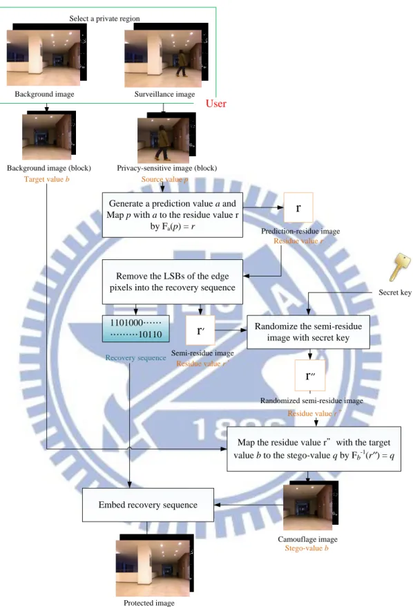
A method for protection of privacy-sensitive regions in surveillance videos acquired by the KINECT device is proposed in this study. This method aims to protect privacy-sensitive images by using a reversible one-to-one prediction-based mapping function proposed by Liu and Tsai [1].
First, we generate a prediction-residue image with small pixel values. Then, we map a privacy-sensitive image and a pre-selected background image together into a third image, called a camouflage image, through the use of the above-mentioned function proposed by Liu and Tsai [1]. The resulting camouflage image is similar to the selected background image and it is hard to tell their differences by human eyes.
At last, in order to recover the privacy-sensitive image, we embed the start and end positions of the selected privacy-sensitive region into the camouflage image in order to generate a new camouflage image involving both the color and depth images,
7
called the protected image. The details of these processes will be described in Chapter 3.
(B) Protection of privacy-sensitive motion activities in surveillance videos
acquired by the KINECT device
A method for protection of privacy-sensitive motion activities in surveillance videos acquired by the KINECT device is also proposed in this study. How to protect selected privacy-sensitive regions has already been studied in the last method, so for this method we propose the use of the speeded up robust features (SURFs) for detecting privacy-sensitive motion activities of specific people in given image sequences or videos.
At first, we detect privacy-sensitive motion events in image frames, and then segment out the region enclosing each motion event in the frame, called protected region. In addition, we modify the appearance of the background image in the protected region. After these steps, we integrate the resulting background image and the privacy-sensitive image together to create a camouflage image by using the previously-mentioned prediction-based mapping function.
At last, we embed the start and end positions of the protected region and the parameters into the camouflage image which involves the color and depth images. The details of the proposed method and the employed SURF extraction technique will be described in Chapter 4.
(C) 3D Steganography via KINECT Images
A method for 3D steganography via KINECT images is proposed in this study. In this method, a technique is proposed to recover the secret image from the camouflage
8
image only by use of the embedded recovery information.
At first, we modify the pixel values of a given 3D cover image according to certain color and coordinate tables. Next, we embed the secret image into the cover image to produce a camouflage image. The original 3D image data we want to recover should be saved, and the recovery information for this purpose is created, called the recovery sequence. Then, we transform the resulting camouflage image into color and coordinate tables.
Finally, the recovery sequence is embedded into the resulting camouflage image by a LSB-modification scheme. With this recovery sequence, the modified cover image part during the data embedding process as well as the hidden secret image can both be retrieved losslessly. The details of these processes will be given in Chapter 5.
1.4 Contributions
Some major contributions achieved in this study are listed as follow.
(1) A method of data hiding using both prediction-based mapping and reversible contrast mapping are proposed.
(2) New applications of the proposed data hiding techniques in video surveillance and steganography are suggested.
(3) A method is proposed to remove the privacy-sensitive image parts from given image sequences or videos, as well as to retrieve it when required. (4) A method is proposed to synchronize removals of corresponding areas in
both the color and depth images.
(5) A method for embedding a 3D image into another with a 3D steganography effect is proposed.
9
1.5 Thesis Organization
In the remaining parts of this thesis, the related works about privacy protection in video surveillance, data hiding in images and 3D steganography via KINECT images are reviewed in Chapter 2. The proposed methods for protecting privacy-sensitive regions and privacy-sensitive motion activities in surveillance videos are described in Chapters 3 and 4, respectively. The proposed method for 3D steganography via KINECT images will be introduced in Chapter 5. Finally, conclusions and some suggestions for future works will be presented in Chapter 6.
10
Chapter 2
Review of Related Works
2.1 Review of Techniques for Privacy
Protection in Video Surveillance
Applications
As global security concerns are now escalating, important video surveillance solutions have been proposed for applications of national security, law enforcement, public transportation, etc. They not only monitor people in various environments, but also expose unintentionally information with personal privacy. For this reason, privacy protection becomes indispensable in video surveillance. In this section, we will review those techniques proposed for privacy protection in video surveillance.
Paruchuri et al. [2] gave a survey of data hiding techniques for protecting privacy-sensitive contents in surveillance videos. To protect the privacy of selected individuals in videos, the usual way is to erase, blur, or re-render the image parts or frames of the individuals. Such modifications, however, destroy the authenticity of the original content of the surveillance video in concern. Paruchuri et al. [2] proposed a new rate-distortion based video data hiding algorithm for the purpose of storing the privacy-sensitive information in the compression domain. The algorithm embeds the privacy-sensitive information in optimal locations that minimize the resulting perceptual distortion and bandwidth expansion due to data embedding. Both reversible and irreversible embedding techniques were considered within the proposed framework, and extensive experiments were performed to demonstrate the
11
effectiveness of the techniques.
Elaine et al. [3] used the face recognition technique to automatically identify known people, such as against a database of driver-license photos. Moreover, they tracked people regardless of suspicion, guaranteeing that face recognition software will not recognize de-identified faces reliably, even though many facial characteristics were preserved. Also, the system obliterated relevant information, for example, object tracks or suspicious activities, from videos.
Dufaux et al. [4] also introduced a method to protect personal privacy by scrambling image regions containing personal information. As a result, the scene remained visible, but the privacy-sensitive information was not identifiable any more.
2.2 Review of Techniques for
Information Hiding Techniques
With the advance of computer technology, information hiding has already become an indispensable part of our lives. In this field, videos, pictures, and digital audios are furnished with distinguishing abilities but imperceptible marks, which may contain a hidden patent or information, or even help to prevent modifications of its own.
Many data hiding methods have been proposed for still images. They can be classified into two main categories: (1) spatial-domain and (2) frequency-domain. In a spatial-domain method, the secret message is usually embedded by using LSB, statistical, feature, or block-based techniques. These techniques work with the pixel values directly, and images are generally manipulated by altering one or more bits of each byte of the image. On the other hand, in a frequency-domain method, a secret message is hidden in the coefficients of the image in the transform domain.
12
Generally speaking, the spatial-domain method is sensitive against attacks like image compression, resulting in quality degradations and content distortions, but the frequency-domain method is more robust. Therefore, data hiding in the frequency domain is less prone to attacks, but a lot of people prefer to use spatial-domain modification since it can hide more data.
For example, Ni, et al. [5] proposed a reversible data hiding algorithm for embedding data in the spatial domain by using the zero or the minimum point of the histogram and slightly modifying the pixel values. Also, Xuan et al. [6] proposed an approach to hiding data into the middle biplanes of the integer wavelet transform coefficients in the middle and high sub-bands of the frequency domain.
Besides, the most popular hiding technique may be the least-significant-bit (LSB) replacement. This method has been improved, extended, and revisited for years because the traditional LSB replacement method has many weaknesses, like distortion incurring, inherent fragility, etc. Even reversible LSB replacement methods havw been developed, which are very useful for visible watermarking and covert communication.
For example, Celik et al. [7] proposed a method for data embedding using lossless generalized LSB replacement. This method modifies the lowest levels, instead of the bit plane, of raw pixel values, and can recover the original image by compressing and transmitting the modified level values.
2.3 Review of Techniques for Image
Steganography
Steganography is the art of writing hidden messages in such a way that no one, apart from the sender and intended recipient, suspects the existence of the message. It
13
may be regarded as a form of security through obscurity.
Generally, messages will appear to be something else: images, articles, shopping lists, or some other cover texts. The advantage of steganography over cryptography alone is that messages do not attract attention to themselves. Plainly visible encrypted messages, no matter how unbreakable, will arouse suspicion and may in themselves be incriminating in countries where encryption is illegal. Therefore, whereas cryptography protects the contents of a message, steganography can be said to protect both messages and communicating parties.
Lee et al. [8] proposed a method of watermarking which embeds an autostereogram into a cover image by the discrete cosine transform (DCT). This not only improves the low bit capacity but also the watermark efficiency because the random dots are distributed in the image space.
In [9], Wang and Chen presented an image steganography method that utilizes a two-way block-matching procedure in order to search for the highest similarity block for each block of the secret image. The indexes of these secret blocks are obtained in a block-matching procedure and recorded in the least significant bits of the cover image. Recently, Tsuda et al. [10] proposed a modified secure and high-capacity based steganography scheme for hiding a large-size secret image into a small-size cover image. The results show that the proposed algorithm for the modified steganography is highly secured in addition to having good perceptual invisibility.
2.4 Previous Studies on Applications of
KINECT Devices
The KINECT device incorporates several types of advanced sensing hardware. The most notable is that it contains a depth sensor, a color camera, and a
14
four-microphone array, providing a full-body 3D motion capture device with face and voice recognition capabilities. The KINECT device is shown in Figures 2.1 and 2.2.
In more detail, the depth sensor in the KINECT device can emit an IR pattern, and capture the return signals as an IR image with a traditional CMOS camera that is fitted with an IR-pass filter.
Figure 2.1 The outer appearance of a KINECT sensor.
Figure 2.2 The KINECT device is composed of an Infra-red (IR) projector, an IR camera, and an RGB camera
15
The image processor of the KINECT device uses the relative positions of the dots in the pattern to calculate the depth displacement at each pixel position in the image. It is noted that the actual depth values are the distances from the camera-laser plane rather than from the sensor itself. As such, the depth sensor can be seen as a device that returns the coordinates of 3D objects.
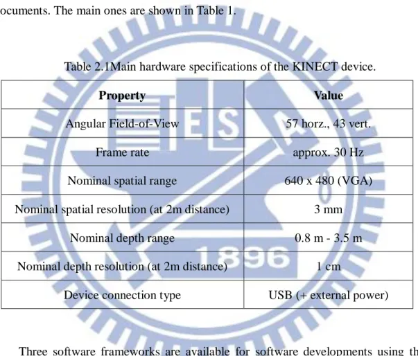
The hardware specifications of the KINECT device are described in many documents. The main ones are shown in Table 1.
Table 2.1Main hardware specifications of the KINECT device.
Property Value
Angular Field-of-View 57 horz., 43 vert. Frame rate approx. 30 Hz Nominal spatial range 640 x 480 (VGA) Nominal spatial resolution (at 2m distance) 3 mm
Nominal depth range 0.8 m - 3.5 m Nominal depth resolution (at 2m distance) 1 cm
Device connection type USB (+ external power)
Three software frameworks are available for software developments using the KINECT device: Microsoft SDKs [11], OpenNI [12], and OpenKinect [13]. The Microsoft SDK is available only for Windows 7 whereas the other two frameworks are multi-platform and open-source software.
With the development of the depth camera technology, it is feasible to get high-quality color and depth images synchronously in realtime using the KINECT device now. Zhao et al. [16] compared the performances of different ways of
16
extracting interest points, and showed that the best performance could only be achieved by extracting interest points solely from the RGB channels, and then computing RGB-based descriptors and depth map-based descriptors together with those interest points.
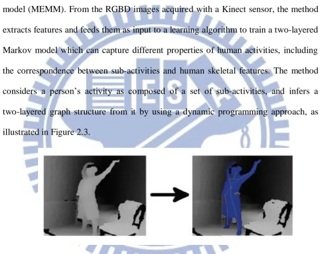
In [17], Sung et al. proposed a method of using the KINECT device to extract human motions. The method was based on a hierarchical maximum-entropy Markov model (MEMM). From the RGBD images acquired with a Kinect sensor, the method extracts features and feeds them as input to a learning algorithm to train a two-layered Markov model which can capture different properties of human activities, including the correspondence between sub-activities and human skeletal features. The method considers a person’s activity as composed of a set of sub-activities, and infers a two-layered graph structure from it by using a dynamic programming approach, as illustrated in Figure 2.3.
Figure 2.3 An example of extracting human activities from the RGBD data acquired with the Kinect sensor conducted by Sung et al. [17].
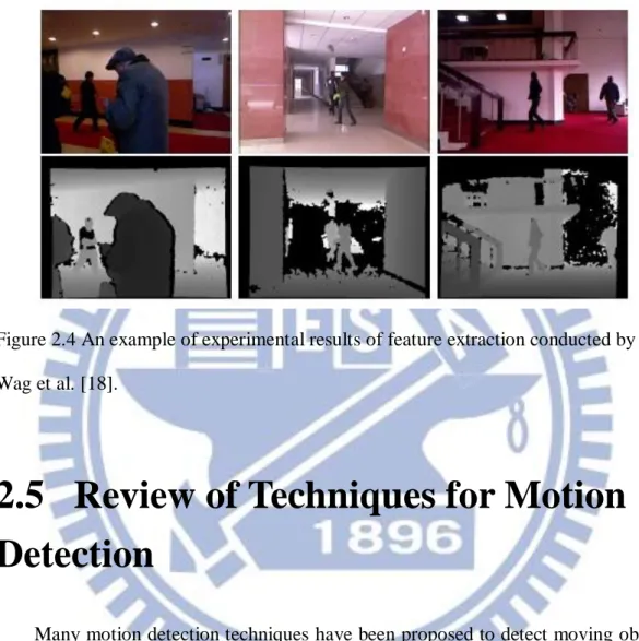
At last, Wang et al. [18] proposed a new feature descriptor, Pyramid Depth Self-Similarities (PDSS), for depth images. It was based on the idea that the depth information of people has high local self-similarities. Pedestrian detection was performed restrictively to single images, which involves three key aspects: feature, classifier, and detection strategy. To yield a better performance, it was suggested to
17
look for better features, as people present different somatotype and appearances, as illustrated in Figure 2.4.
Figure 2.4 An example of experimental results of feature extraction conducted by Wag et al. [18].
2.5 Review of Techniques for Motion
Detection
Many motion detection techniques have been proposed to detect moving objects in videos [19-24], and some of them are reviewed in this section.
The main purpose of motion detection is to identify motion areas in a video, or to segment out motion objects from a video. A lot of content-based applications, such as smart signal processing, computer vision analysis, etc., have been developed. And their common works are often to detect motion objects firstly, and then to identify the properties of the objects for various applications.
Related techniques include human-face detection and recognition, motion-object tracking, content-based video retrieval, etc. Existing motion detection techniques can
18
be classified into two categories: one for use in the pixel domain [25-26] and the other in the compressed domain [27-29]. Generally speaking, the approaches used in the pixel domain have to fully decode a compressed video bitstream first, but they can be employed for videos coded according to different video coding standards. On the other hand, each of the approaches used in the compressed domain can perform a motion detection process by partially decoding a compressed video bitstream, but they can only be employed in videos coded according to specific standards.
Lipton et al. [19] proposed another approach which is based on temporal differencing in the pixel domain, where temporal differencing means the pixel-wise value differences between consecutive video frames. The basic idea of this approach is to compare video frames that are separated by a constant time in order to find moving objects. Haritaoglu et al. [20] also proposed a motion detection method which is based on background subtraction in the pixel domain. Both of the two methods built a statistical model for a background scene, and used the model to detect moving objects even though the background scene was not completely static.
19
Chapter 3
Protection of Privacy-sensitive
Regions in Surveillance Videos
Acquired by KINECT Device
3.1 Introduction
With the increasing public concern about personal privacy protection issues, it is desired to develop privacy protection methods for use in video surveillance systems. Besides, with the rapid development of stereo-vision technology, 3D imaging devices become more and more popular. Many types of such devices have been invented to get 3D multimedia information under various conditions. One famous example is the KINECT device manufactured by Microsoft.
Accordingly, in the application of video surveillance, we can get easily from 3D image data such information as intruding persons, their heights and thicknesses, and so on. Because of these characteristics and usefulness of 3D image data, the issue of protecting 3D image data in various applications becomes more and more important. In this chapter, we describe the proposed method for privacy protection of selected privacy-sensitive regions in image frames of surveillance videos taken with the KINECT device.
In Section 3.1.1, the related problem definitions are given. In Section 3.1.2, the related ideas are reviewed and the basic idea of the proposed method is described. The
20
principle behind the proposed method is based on the concept of merging of processed color and depth images to display 3D information, which we describe in Section 3.2. Detailed algorithms for privacy-sensitive region concealment and recovery based on the principle are presented in Section 3.3. Finally, some experimental results showing the feasibility of the proposed method are given in Section 3.4.
3.1.1 Problem Definition
As security surveillance is extensively applied in our living environment, there is a growing concern that the systems pose threats to personal privacy. Since the feeling of privacy is highly subjective and varying across cultures and individuals, the method of privacy protection should be adapted as much as possible to suit individual requirements. With regard to this demand, in the proposed method we allow an authorized user to specify a privacy-sensitive region R in a surveillance video in advance. The image content in R is defined as a privacy-sensitive image part which is not to be revealed to unauthorized people. The goal of the proposed method is to disguise the pre-selected privacy-sensitive image part as a corresponding background image part to conceal privacy-sensitive information in the image frames of the surveillance video. In addition, it is hoped that the protected image frames can be restored to include the original privacy-sensitive image part if a secret key is given as input.
Using traditional data hiding techniques to hide the privacy-sensitive image part may achieve this goal, but such techniques usually are time-consuming and demand large spaces for data embedding. Therefore, we design alternatively a general method for concealing the privacy-sensitive image part imperceptibly and recovering the original content of this image part from the resulting protected image losslessly. In
21
addition, even if a person knows the algorithms implementing the method, he/she still cannot retrieve the privacy-sensitive image part without the secret key. The security of the protected privacy in the surveillance video is thus ensured.
On the other hand, the KINECT sensor can be used to acquire the depth information, so the data can be used more extensively in applications than the 2D data. This kind of information is very important, so its correctness must be guaranteed. It is noted that the range of the depth values that are provided by the KINECT device is different from that of the general values of color-image. On the other hand, together with a depth image, a color image is taken simultaneously by the KINECT device. So, the depth image and the color image taken by the KINECT device at an identical instant of time should be protected together to keep their relation in time.
3.1.2 Review of Ideas of a Previous Study
Camouflaging is a method of hiding a secret. It allows a secret to be disguised by an object and so remain unnoticed. The major idea of the proposed method was inspired by the concepts of camouflaging and privacy protection in surveillance videos which were proposed by Lin and Tsai [25] as well as by the natures of the features of the KINECT images. The proposed method aims to produce a protected image by disguising a privacy-sensitive image part as a pre-selected background image part in a surveillance video, and to protect as a whole the color and depth images taken by a KINECT device at an identical instant. The proposed method utilizes the features of KINECT images and the range of pixel values in the depth image to achieve the goal of protecting the color and depth image together.
Specifically, the proposed method produces a camouflage image by using a prediction-based mapping, which a deterministic one-to-one (reversible) compound mapping function proposed originally by Liu and Tsai [1]. Following the function
22
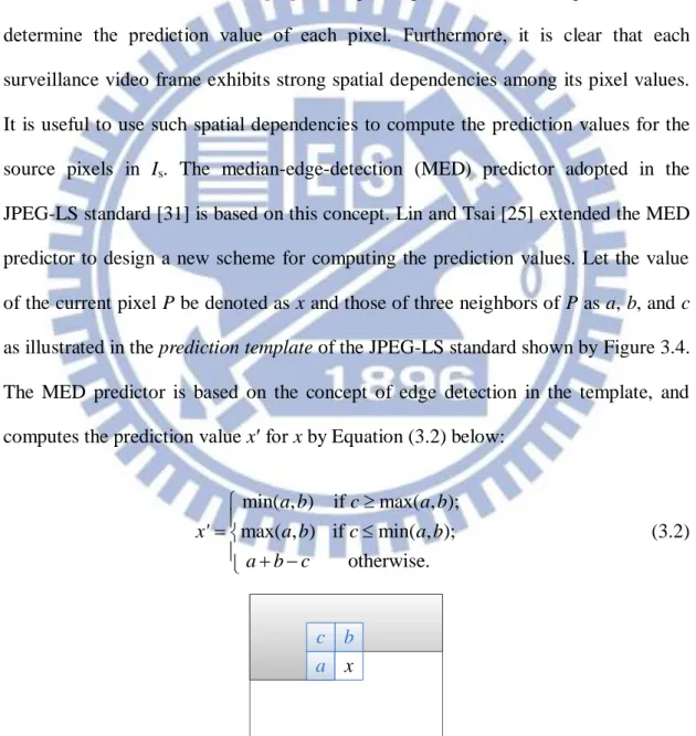
proposed originally by Liu and Tsai [1], Lin and Tsai [25] integrated a new prediction technique into the prediction-based mapping to make the resulting camouflage image closely resemble the background image in appearance. The technique they proposed can estimate more effectively pixel values for use in the prediction-based mapping. Specifically, it uses the pixel-value similarity among adjacent pixels and employs a simple edge detection technique coming from the JPEG-LS standard [31].
3.2 Proposed Techniques of
Synchronized Removals of
Corresponding Areas in Color and
Depth Images
In this section, we introduce the method proposed in this study which synchronously removes corresponding areas in color and depth images for privacy-sensitive image part concealment. The principle behind the proposed method is based on Lin and Tsai [25] as mentioned. In Section 3.2.1, the idea of the proposed method is described. And in Section 3.2.2, the detailed algorithms implementing the method are described.
3.2.1 Idea of Proposed Method
In the proposed method, at first a scheme is proposed to generate a new 3D image from the color and depth images acquired with a KINECT device. It is known that the KINECT device has a color camera and a laser sensor which are not aligned, leading to a displacement between the coordinates of the color image and those of the depth image. Therefore, we must correct this displacement to merge the two images to
23
produce a single 3D image. We conduct this correction based on the use of a pinhole camera model.
The next major step of the proposed method is to disguise the privacy-sensitive image part as a pre-selected background image part to conceal the privacy-sensitive information in the image frames in the surveillance video. For this, we allow an authorized user to specify a privacy-sensitive region R in a surveillance video in advance, followed by the action of disguising the image content as mentioned above.
The third major step is to remove synchronously corresponding areas in the color and depth images in the mean time. The result is finally displayed in a 3D fashion. More details are described in the following.
3.2.2 Merging of Processed Color and Depth Images
To merge the depth and color images to produce a 3D image, a calibration of the camera parameters in advance is necessary. In this process, a rotation problem and a displacement problem in the 3D space should be solved at first. A solution to the rotation problem is to correct related parameters before mapping the KINECT images (including color and depth images) to produce an integrated 3D image. For this, some functions and parameters provided by the KINECT device and the Kinect-for-Windows SDK [11] can be utilized. In more detail, we tilt the field of view of each KINECT device to the zero-angle position using the tilt motor in the KINECT device before acquiring KINECT images; and to solve the displacement problem between the color image and the depth image, we use certain functions provided by the Kinect-for-Windows SDK [11].
After the above problems are solved, the original color and depth images are aligned in the same image coordinate system. But these 3D image data are just the 3D depth coordinates combined with the 2D image coordinates, so they must be
24
transformed into a single 3D space coordinate system integrally. For this purpose, we apply the principle of the pinhole camera model to conduct the transformation of the image coordinates into the 3D space coordinates.
Pₐ (u, v) f lens center P (X, Y, Z ) image plane camera coordinates system X’ Z’ Y’ x y Z d D image coordinates system O C G’ Principal Axis
Figure 3.1 The pinhole camera model.
As illustrated in Figure 3.1, the pinhole model may be considered to be a simple camera with its center of projection (i.e., its lens center) located at O and its optical axis taken to be the Z-axis of the camera coordinate system. The focus point is on the image plane with a focal length f. A 3D space point P = (X, Y, Z) in the camera coordinate system is projected onto an image point Pa on the image plane at image
coordinates (u, v), where the image plane may be that of the depth image or the color image. The depth value d of the space point P is provided by the KINECT device, but we do not have its correct coordinates (X, Y, Z) in the 3D space (i.e., in the camera coordinate system). We can calculate them according to the similar-triangle principle.
25
In more detail, following the direction vector starting from the center C of the image plane, going through lens center O of the camera, and finally reaching at a 3D space point G' which is the projection of the space point P on the vector, we can see two similar triangles aside the direction vector. We can calculate the distance d between the image plane and the lens center O by the following equation:
2 2 2 f v u d . (3.1)
Then, according to the principle of similar triangles, we can derive the following equalities: Y v X u Z f . (3.2)
which lead to:
; fX fY u v Z Z .
Accordingly, we can derive the following equations to describe the relation between the image coordinates (u, v) and the corresponding coordinates (X, Y, Z) using homogeneous coordinates:
0 0 0 1 1 ; 0 0 0 1 0 0 1 0 1 1 X X X u fX f u Y Y Y v fY f v Z Z Z Z Z Z (3.3)
Using the above results, we can start to merge the color and depth images acquired by the KINECT device. The detailed algorithm is described in Algorithm 3.1 below.
Algorithm 3.1: merging of color and depth images. Input: a depth image D, a color image C.
26
Steps:
Step. 1 Perform the process of Equations 3.1 through 3.3 to “calibrate” the pixels in color image C and those in depth image D, with a pixel Cp in the resulting C
having values (Cr, Cg, Cb), and a depth pixel Dp in the resulting D having
values (Dx, Dy, Dz).
Step. 2 Transform each pixel index Ci of color image C into the pixel index Di of
depth image D, where C is four times as big as D, by the function Di =
Ci/4.
Step. 3 In a raster-scan order, take a pixel Dp from the depth image D and a
corresponding pixel Cp from the color image C.
Step. 4 Knowing the extrinsic rotation R and translation T between the color and depth camera, express the mapping between color image pixel Cp and depth
image pixel Dp by following equations: R T
D D D C C C z y x b g r .
Step. 5 Construct the 3D image J by u J f J J z x xp ; v J f J J z y yp to find the color information corresponding to each 3D point. The space coordinates (Jx, Jy, Jz) of a 3D point can be used to find the coordinates (Jxp,
Jyp) of the corresponding image point, and draw these 3D point in the 3D
space by the OpenGL.
In the above algorithm, the values of R and T are given by following equations:
x x x x x x R cos sin 0 sin cos 0 0 0 1 ;
y y y y y y R cos 0 sin 0 1 0 sin 0 cos
1 0 0 0 cos sin 0 sin cos z z z z z z R ; 1 0 0 0 1 0 0 0 1 0 0 0 1 Z Y X27
3.3 Proposed Method for Protecting
Selected Privacy-sensitive Regions in
Surveillance Videos
In this study, we adopt the processes for reversible prediction-based mapping from the previous study of Liu and Tsai [1] and Lin and Tsai [25]. About the processes for reversible prediction-based mapping, we will discuss problems encountered in applying the mapping, and propose solutions to them. Subsequently, they will be applied to security protection for video surveillance in Section 3.3.1. And the complete processes of privacy-sensitive region concealment and recovery are presented in Sections 3.3.2 and 3.3.3, respectively. The detailed algorithms about the proposed methods and the complete processes of concealing and recovering privacy-sensitive image parts will be presented in this section.
3.3.1 Review of application of reversible
prediction-based mapping to privacy protection in
surveillance videos
The method for privacy protection in surveillance videos is based on the use of the reversible prediction-based mapping proposed by Liu and Tsai [1], which is a deterministic one-to-one compound mapping of values. Besides, Lin and Tsai [25] proposed a principle of mapping and its use for protection of pre-selected privacy-sensitive regions will be described in this section.
As proposed in Liu and Tsai [1], a one-to-one mapping Fc with the function of
28
the values of the adjacent pixels of P in the image are usually close to p because of contextual dependency. So, if we compute the average value a of them, a will be usually close to p and can be regarded as a prediction value of p. Therefore, we can take a as the parameter c of the function Fc above so that Fc(p) = Fa(p) = p c = p a
will be usually small because a is close to p in value. This function value will be called the prediction residue of p and denoted as r subsequently, i.e., Fa(p) = p a = r.
Next, a second one-to-one mapping Fb-1(r) = r + b is performed, which adds r to
the target value b, where Fb1 is the inverse of F with parameter b. The resulting value
is denoted as q. The overall 2-step mappings result in a compound one-to-one mapping function f with the following effect: f(p) = Fb1(r) = Fb1(Fa(p)) = r + b = (p
a) + b = q.
As stated above, r = p a is usually close to 0, so the value q = f(p) will be close to the target value b, creating an effect of steganography. Therefore, we will call q a
stego-value. Also, it is obvious that the smaller the prediction residue value r, the
closer the stego-value q is to the target value b.
If it is desired to recover p from q, then the inverse f 1 of the compound one-to-one mapping function f can be used and the recovery is lossless, as can be seen from the following derivations:
f1(q) = [Fb1(Fa(q))]1 = Fa1(Fb(q)) = Fa1(q b)
= Fa1(p a + b b) = Fa1(p a) = p a + a = p.
Accordingly, to recover p from q, first we retrieve the prediction residue value r = p a by computing the value of the inverse Fb of the second mapping function Fb1
with the stego-value q as input. This results in Fb(q) = q b = p a + b b = p a = r.
Then, we use the same prediction scheme to compute the prediction value a from the values of the pixels adjacent to pixel P. Finally, we use the inverse Fa1 of the first
29
= p a + a = p.
It is noted that in the above recovery process, we have to compute the same prediction value a first, and then use it to recover the original value of the source pixel
P. Based on this principle, Lin and Tsai [25] did not use the original value of the pixel P, but use only the values of the pixels adjacent to P, to compute a for the purpose of
producing the identical prediction value.
In the previous method, conversion of a source value into a stego-value by two simple mapping function Fa(p) = p – a = r and Fb-1(r) = r + b = q will cause some
problems. The computed stego-value q might exceed the range of valid pixel values of
a, b, and p. Then, Lin and Tsai [25] proposed another way to solve this problem.
To solve this problem, Lin and Tsai [25] adopted another one-to-one mapping function Fc proposed in [1] with c = a or b such that the compound mapping q =
Fb–1(Fa(p)) did not exhibit this wrap-around problem. Based on this new function Fc,
we describe how the corresponding mappings Fa(p) and Fb1(r) work, respectively, by
Algorithms 3.2 and 3.3 below.
Algorithm 3.2: computing the value of a new mapping function Fa(p) which does not
cause the wrap-around problem.
Input: a prediction a and a source pixel value p.
Output: the prediction residue r of the mapping function Fa(p) without causing the
wrap-around problem.
Steps:
Step. 1 Initialize r to be zero.
Step. 2 Create a set S with 256 initial elements 0 through 255.
Step. 3 Find a value p in S such that |a – p| is the minimum, preferring a smaller p in case of ties occur.
30
Step. 4 If p is not equal to p, then remove p from S, increment r by one, and go to Step 3; otherwise, take the final r as the output.
Algorithm 3.3: computing the value of the inverse Fb1(r) of the mapping Fa(p)
described by Algorithm 3.2.
Input: a target value b and a prediction residue value r.
Output: an stego-value q of the inverse mapping function Fb1(r) of Fa(p)
Steps:
Step 1 Create a set S with 256 initial elements 0 through 255.
Step 2 Find a value q in S such that |b – q| is the minimum, preferring a smaller q in case of ties.
Step 3 If r is larger than 0, then remove q from S, decrement r by 1, and go to Step 2; otherwise, take the final q as the output.
Based on the above two algorithms, the ideas for converting the source value p into a stego-value q and recovering p from q losslessly now can be described integrally by Algorithms 3.4 and 3.5, respectively, below.
Algorithm 3.4: converting a source pixel value to a stego-value which is close to a
target pixel value.
Input: a source value p, a target value b, and the mapping Fc and its inverse Fc-1
described by Algorithms 3.2 and 3.3, respectively, where c is a parameter.
Output: a stego-value q. Steps:
Step 1. Compute a prediction value a by a prediction technique.
Step 2. Perform Algorithm 3.2 to compute the prediction residue value r = Fa(p).
31
Algorithm 3.5: recovering a source pixel value from a stego-value.
Input: the stego-value q produced by Algorithm 3.4 and the target b used there. Output: the source value p.
Steps:
Step 1. Compute the prediction value a by the same technique as used in Step 1 of Algorithm 3.4.
Step 2. Regard the input values b and q as a and p, respectively, and take them as inputs to Algorithm 3.2 to compute a prediction residue value r.
Step 3. Regard a obtained in Step 1 as b, and take it and the value r obtained in Step 2 as inputs to Algorithm 3.3 to compute the source value p as the output.
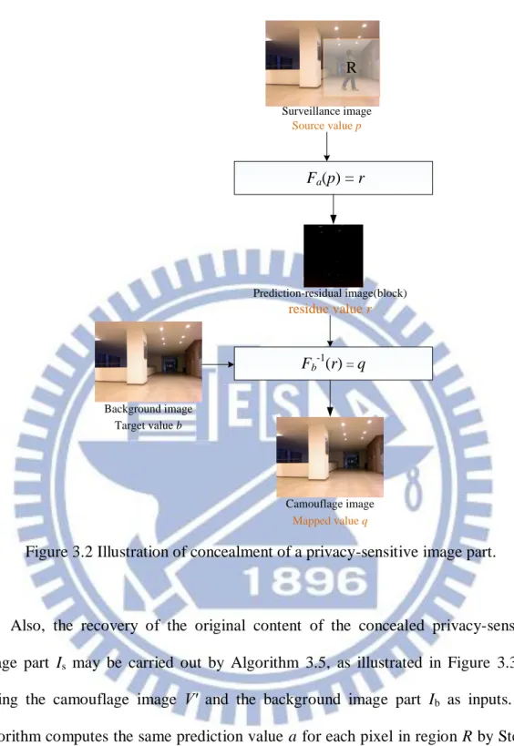
The principle of reversible prediction-based mapping described above was applied to accomplish privacy protection in a surveillance video in the previous review. Lin and Tsai [25] regarded the source value p as a pixel value in a privacy-sensitive image part Is to be protected, which appears within a region R,
called privacy-sensitive region, in every surveillance video frame V other than a pre-selected video frame Vo taken as a background image.
Also, Lin and Tsai [25] used a background image part Ib in Vo, which
corresponds to Is in position in R but without privacy information, to replace Is using
reversible prediction-based mapping described above. Each pixel value in Ib is just a
target value b mentioned previously. Then, as illustrated in Figure 3.2, we may use Algorithm 3.4 to find a prediction value a for each pixel in Is by Step 1 of the
algorithm, yield a prediction-residue image part Ir consisting of the prediction residue
values r in region R by Step 2, and finally generate a camouflage image V′ with stego-values q in region R by Step 3.
32 Source value p Fa(p) = r Prediction-residual image(block) residue value r Fb-1(r) = q Target value b Background image Camouflage image Mapped value q Surveillance image R
Figure 3.2 Illustration of concealment of a privacy-sensitive image part.
Also, the recovery of the original content of the concealed privacy-sensitive image part Is may be carried out by Algorithm 3.5, as illustrated in Figure 3.3, by
taking the camouflage image V′ and the background image part Ib as inputs. The
algorithm computes the same prediction value a for each pixel in region R by Step 1, yields the prediction-residue image part Ir by Step 2, and recovers finally the original
privacy-sensitive image part Is with source values p in R by Step 3, which may used to
33
Target value b
Background image Camouflage image
Mapped value q
F
b(q)
= r Prediction-residual image(block) residue value rF
a-1(r)
= pR
Figure 3.3 Illustration of proposed method of recovery of the privacy-sensitive image part from a camouflage image in a surveillance video.
An important principle to develop the function to compute the prediction value for the source value of each pixel in the privacy-sensitive image part Is is that the
function should use as input only the values of those pixels adjacent to the current pixel P, excluding that of P itself. The reason for adopting this principle is that we want to use the same prediction values for the prediction-based mappings to recover the original pixel values, and this principle ensures that the same prediction value can be computed for each pixel in Is in both the privacy concealment and recovery

![Figure 3.6 Example of quality improvement results by Lin and Tsai [25]. (a)](https://thumb-ap.123doks.com/thumbv2/9libinfo/8235673.171149/49.892.150.744.105.806/figure-example-quality-improvement-results-lin-tsai.webp)
![Figure 3.8 An example of reducing prediction residue by Lin and Tsai [25].](https://thumb-ap.123doks.com/thumbv2/9libinfo/8235673.171149/50.892.139.767.276.896/figure-example-reducing-prediction-residue-lin-tsai.webp)