國
立
交
通
大
學
電機學院 電子與光電學程
碩
士
論
文
MS 在 RS 系統的路徑重新選擇機制
MS Path Reselection Mechanism In Multi-Hop Relay System
研 究 生:吳明錫
指導教授:黃經堯 教授
MS 在 RS 系統的路徑重新選擇機制
MS Path Reselection Mechanism In Multi-Hop Relay System
研 究 生:吳明錫 Student:Ming-Shyi Wu
指導教授:黃經堯 教授 Advisor:Ching-Yao Huang
國 立 交 通 大 學
電機學院 電子與光電學程
碩 士 論 文
A ThesisSubmitted to College of Electrical and Computer Engineering National Chiao Tung University
in partial Fulfillment of the Requirements for the Degree of
Master of Science in
Electronics and Electro-Optical Engineering September 2008
Hsinchu, Taiwan, Republic of China
Table of Contents
摘要 ……… i Abstract ……… ii 誌謝 ……… iii List of Figures ……… iv List of Tables ……… vi Chapter 1 Introduction……… 1Chapter 2 Introduction of Relay Station Technique……… 4
2.1 The Purpose to Use Relay Station……… 6
2.1.1 The Feature to Use Relay Station……… 6
2.2 Data/control plane of Relay Station……… 9
2.2.1 Network entry and initialization……… 9
2.2.1.1 MS network entry procedures in transparent RS systems……… 9
2.2.1.2 MS network entry procedures in non-transparent RS systems……… 10
2.2.1.3 RS grouping……… 15
2.2.2 Ranging……… 17
2.2.2.1 MS periodic ranging and automatic adjustments in transparent RS systems……… 18
2.2.2.2 MS periodic ranging and automatic adjustments in non-transparent RS systems……… 18
2.2.3 Relay path management and routing……… 22
2.2.4 Relay station neighborhood discovery……… 22
2.2.5 Interference measurement for MR……… 23
2.2.6 Messages and data relaying……… 24
2.2.7 RS service end……… 26
Chapter 3 Handover Procedure and Problem Statement……… 27
3.1 Introduction of MAC layer handover procedure in 802.16e………… 27
3.1.1 Network topology acquisition……… 28
3.1.2 Association procedure……… 29
3.1.3 Handover Process……… 32
3.2 Introduction of MAC layer handover procedure in 802.16j………… 35
3.2.1 Network topology acquisition……… 35
3.2.2 Association procedure in an MR network……… 36
3.2.2.1 Association parameter acquisition……… 36
3.2.2.2 Association level 0 and 1……… 37
3.2.2.3 Association level 2……… 37
3.2.3 Handover process……… 39
3.2.4 Mobile relay station handover……… 39
3.2.5 MS handover procedure involving RS……… 41
3.2.5.1 MS movement among access stations with different preamble/FCH/MAP……… 41
3.2.5.2 MS movement among access stations with same preamble/FCH/MAP……… 41
3.2.7 Problem statement in Intra-MR-BS handover……… 44
3.2.8 Proposed path reselection mechanism……… 45
3.2.8.1 Target access station reselection metric……… 46
Chapter 4 Simulation models Setup……… 47
4.1 The simulation environment setup……… 47
4.1.1 Base station deployment……… 47
4.1.2 Link budget……… 48
4.1.3 Relay station deployment……… 51
4.2 Path reselection model setup……… 52
4.2.1 SINR……… 52
4.2.2 Hop counts……… 54
Chapter 5 Simulation result……… 56
5.1 Analysis of MS handover without path reselection mechanism……… 56
5.1.1 Ping-Pong effect versus number of relay stations……… 56
5.1.2 Ping-Pong effect versus MS mobility……… 58
5.1.3 Ping-Pong effect versus number of users……… 59
5.2 Analysis of MS handover with path reselection mechanism………… 61
5.2.1 Ping-Pong effect versus all constraints……… 61
5.2.2 Ping-Pong effect versus only SINR strength marginal addition……… 63
5.2.3 Ping-Pong effect versus different constraint……… 64
5.2.4 SINR comparison……… 66
Chapter 6 Conclusion and future work……… 68
MS 在RS 系統的路徑重新選擇機制
學生: 吳明錫 指導教授: 黃經堯博士
國立交通大學 電機學院 電子與光電學程碩士班
摘要
Wimax (802.16e)是一種可以在城市範圍大小裡能夠提供眾多使
用者,以及在這大範圍裡提供高速資料傳輸的技術。雖然有很好的科
技來支援這個技術,仍然有許多問題需要去克服,像是如何延長手機
電池的待機和使用時間,如何在高速移動中取得高速傳輸的平衡,以
及如何提高覆蓋範圍,都是急待解決的問題。然而這些問題都可以藉
著導入Relay Station來改善。導入Relay Station有兩個主要的好處:增
加訊號覆蓋範圍和提高訊號傳輸量。但是隨著Relay Station數目的增
加也使得Handover變的比以前來的更頻繁。而有些不必要的Handover
會造成系統的額外負荷以致於訊號傳輸量並沒有提高,並且造成整個
系統資源的浪費和效率的降低。在本篇論文中,一個新的路徑選擇機
制將被導入Handover中來解決Ping-Pong Effect。經過簡單的模擬後,
這 個 路 徑 選 擇 機 制 不 但 可 以 降 低
Ping-Pong Effect 並 且 提 高 在
Handover之後的SINR改善的量。
MS path reselection mechanism in multi-hop relay system
Student: Ming-Shyi Wu Advisor: Dr. Ching-Yao Huang
Degree Program of Electrical and Computer Engineering
National Chiao Tung University
Abstract
WiMAX (802.16e) is technically capable of offering city-wide broadband connections to a high number of mobile terminals and provides high speed transmission over large area. The technology has strong industrial support, however a number of challenges remain to be resolved. Major concerns include battery life for mobile terminals, balancing support for high velocity and high data-rate, and increasing area coverage. Relay Station technology is a promising approach to address these challenges. The two major benefits of Relay Station employment are coverage extension and throughput enhancement. As the number of Relay Stations increases, the handover scenarios happen much more often than that of non-RS system. The Ping-Pong effect increases the system loading and may not enhance the system throughput. Some unnecessary handovers also may result in the waste of resource and decreases the efficiency. In this thesis, a path reselection mechanism will be introduced to resolve the Ping-Pong effect and throughput issues. This method is implemented in the simulation whose result shows the Ping-Pong handover reduction and higher SINR improvement after handover by using this proposed path reselection mechanism.
致謝
光陰似箭,在職碩士班的這幾年即將畫下句點。在這一段過程中,認識許多 好夥伴,其中更有許多是我在研究領域上的貴人,很慶幸有你們的陪伴和幫助, 可以讓我順利的畢業,在此我願意將我小小成果分享給大家。 首先,我要感謝我的指導教授,黃經堯博士,除了在專業上授於我許多關於 無線通訊的知識外,也培養我如何去找出問題、分析問題、最後解決問題的能力。 也感謝老師在這幾年內,讓我自由的從事研究,並讓我好好在原本工作上好好努 力並且利用閒暇時來努力完成應該做的研究,使我可以兼顧工作和學業,如果沒 有黃老師這幾年的支持和信任,我絕對沒有辦法順利畢業。 再來,我要感謝跟我一起奮戰的同學,家弘同學,藉由他的督促和照顧,以 及提供我許多的幫助,還有,白熊學長也提供了我許多研究上面的建議,並且很 有耐心的一一解答我所有的疑惑,由於他們的幫助能讓我順利的完成學業。 最後,要感謝我的家人,爸爸、媽媽、太太還有兩個可愛的兒子,全力支持 我攻讀碩士班並且讓我沒有後顧之憂,使我可以專心的完成學業。家人在背後的 支持,永遠是我動力的泉源。 碩士畢業後,我將讓自己的專業知識更豐富、更紮實,也希望能把這幾年在 學術研究上的研究方法應用到現行的工作上,使目前的工作更加順利。List of Figures
Figure 2-1 Relay Station deployment……… 5
Figure 2-2 Coverage extension……… 5
Figure 2-3 Throughput enhancement……… 6
Figure 2-4 Frame structure of transparent RS……… 7
Figure 2-5 Frame structure of non-transparent RS……… 8
Figure 2-6 RS initialization overview……… 11
Figure 2-7 Ranging and automatic adjustment procedures in transparent mode… 12 Figure 2-8 Ranging and automatic adjustment procedures in MR mode with centralized scheduling……… 13
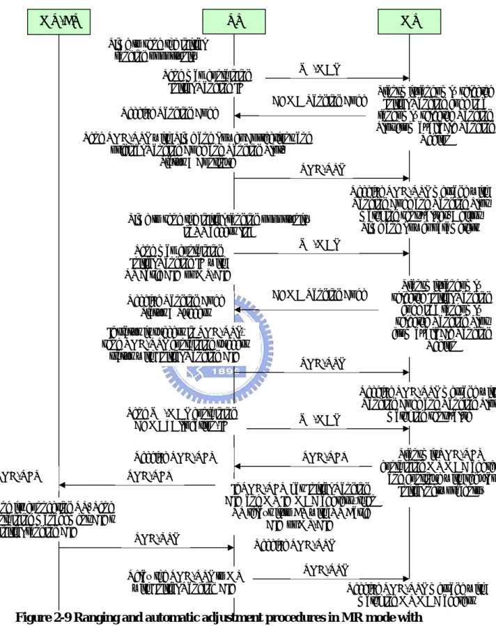
Figure 2-9 Ranging and automatic adjustment procedures in MR mode with distributed scheduling……… 14
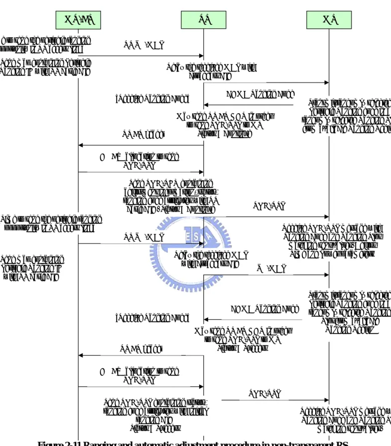
Figure 2-10 Ranging and automatic adjustment procedure in transparent RS system……… 19
Figure 2-11 Ranging and automatic adjustment procedure in non-transparent RS system……… 20
Figure 2-12 Ranging and automatic adjustment procedure in non-transparent RS system with distributed scheduling……… 21
Figure 2-13 Relaying DCD/UCD procedure……… 25
Figure 2-14 DCD/UCD broadcasting with centralized scheduling……… 25
Figure 3-1 MS scanning of neighbor BSs……… 29
Figure 3-2 Association Level 0 – Scan / Association without coordinate……… 30
Figure 3-3 Association Level 1 – Scan / Association with coordinate……… 31
Figure 3-4 Association Level 2 – Network Assisted Association Reporting…… 31
Figure 3-5 Cell reselection……… 32
Figure 3-6 Handover Decision and Initiation……… 33
Figure 3-7 Network Re-entry – Synchronization and Ranging……… 34
Figure 3-8 MS scanning of neighbor BSs……… 36
Figure 3-9 Association parameter acquisition for different MR-cell……… 37
Figure 3-10 Association level 0 and 1……… 38
Figure 3-11 Association level 2……… 38
Figure 3-12 Relay Station Handover Procedure……… 40
Figure 3-13 Handover procedure involving RS with centralized HO control from MR-BS……… 41
Figure 3-14 Seven handover cases in a MR network……… 44
Figure 3-15 The handover situation in a MR network……… 46
Figure 4-1 Base Station Wrap Around Deployment……… 48
Figure 4-2 3 sectors for each base station……… 48
Figure 4-3 Diagram of SINR computation……… 51
Figure 4-4 Example of RS deployment……… 52
Figure 4-5 Example of SINR strength constraint……… 53
Figure 4-6 Example of SINR standard deviation constraint……… 53
Figure 4-8 An appropriate path reselection based on the strength and stability of
link quality in a MR network……… 54
Figure 5-1 Ping-Pong Effect V.S. number of relay stations……… 57
Figure 5-2 Ping-Pong Handover Counts V.S. number of relay stations………… 57
Figure 5-3 Ping-Pong Effect V.S. MS mobility……… 58
Figure 5-4 Ping-Pong Handover Counts V.S. MS mobility……… 59
Figure 5-5 Ping-Pong Effect V.S. MS Counts……… 60
Figure 5-6 Ping-Pong Handover Counts V.S. MS Counts……… 60
Figure 5-7 Ping-Pong Effect V.S. All Constraints……… 62
Figure 5-8 Ping-Pong Handover Counts V.S. All Constraints……… 62
Figure 5-9 Ping-Pong Effect V.S. Only SINR Marginal Constraint……… 63
Figure 5-10 Ping-Pong Handover Counts V.S. Only SINR Marginal Constraint… 64 Figure 5-11 Ping-Pong Effect V.S. Different Constraints……… 65
Figure 5-12 Ping-Pong Handover Counts V.S. Different Constraints……… 66
List of Tables
Table 4-1 Link budget……… 49
Chapter 1
Introduction
Over the last decade, the number of Internet users has an explosive growth. Currently, most broadband Internet access methods are based on wired communications, such as T1, DSL, and cable-modem technologies. However, there are still a large number of areas where wired infrastructures are difficult to be deployed because of technical or commercial reasons. To provide a broadband wireless access solution, proponents are advocating WiMAX, and IEEE 802.16 standardized wireless technology that supports high throughput broadband connections over a wide range. As standardized, WiMAX employs orthogonal frequency division multiplexing (OFDM) in its physical layer. According to the initial 802.16 standard, WiMAX can provide a single-channel data rate of up to 75 Mbps on both UL and DL. If necessary, service providers can use multiple WiMAX channels for a single transmission to reach a bandwidth of up to 350 Mbps.
In generally, the larger distance between mobile stations (MSs) and base stations (BSs) is, the weaker received quality of signal becomes. In order to provide higher throughput, higher data rate and larger coverage in a wireless communication, the traditional way is to increase the transmitting power of BSs or deploy a lot of BSs. Unfortunately, these methods will produce much interference to other neighbor BSs and surrounding MSs and system performance may not be improved. Thus the relaying technologies [1] are proposed to resolve this problem. The basic concept is to deploy some relay stations (RSs) into BS’s cell boundary and RSs forward the received signals from BS and amplify or encode the received signals to its subordinate MSs. By introducing RSs into BS’s cell boundary, higher level of Adaptive Modulation and Coding (AMC) would be used to improve the throughput.
Two types of RSs, transparent and non-transparent RSs, are introduced into IEEE 802.16e [2] network to increase the system throughput and coverage area [3]. The former one is to provide only data transmission but not to transmit control signals such as preamble, MAP, and etc. to its subordinate MSs. In this case, a MS is not aware of the existence of the access RS which is transparent to the MS. The later one is to provide both the control signals and data burst for its subordinate MSs. This type of RS can be considered as a BS that could be measured the signal quality by its
subordinate MS. Handover (HO) would happen more often because of the small coverage of RSs and increasing network nodes. It is known that once Handover happens, the corresponding interruption may cause damages to services continuity and reduce the QoS performance. Therefore, how to reduce the occurring Handover frequency and Handover switching latency are the key issues in multi-hop relaying network.
Up to several new schemes had been proposed. [4] A proposal of “Instantaneous Inter-relay Handover” algorithm is to decide which RS would be the best node for accessing. In this algorithm, it classifies RSs into fixed-RS and mobile-RS and also classifies Inter-relay handovers (IRHO) into Inst-IRHO, No-IRHO, and SIR-IRHO. Because Inter-relay handover (IRHO) occurs in MRS or FRS will impact system performance, simulations show that a good path selection in multi-hop relaying network can gain a lot of system capability. A network Coding combined with HO technique is proposed in [5]. With this method, the diversity gain can be acquired between RS and MR-BS to resolve the mobility management with lower outage probability. The hierarchical ID management is also designed in [6]. This management makes MS easy to distinguish intra-cell stations and inter-cell station and the intra-cell handover rate increases to enable lower HO overhead. A novel handover method that reduces inter-cell handover but increases intra-cell handover events is introduced. The purpose of this method is to decrease signaling overhead, latency, and ping-pong effect by the major evaluation metric which including CINR and cell ID information.
In some contribution [7 ~ 15], the problems of MS handover in multi-hop relay network are described. Seven handover cases in an MR network are defined in [7]. These seven cases can be classified into two group, Intra-MR-BS handover and Inter-MR-BS handover. In Inter-MR-BS handover, MS shall conduct 802.16e [2] compliant handover procedures for backward compatibility. MS can sense the handover procedure, so the legacy 802.16e handover mechanism can be reused. [11]
In Intra-MR-BS handover, some issue should be clarified and resolved. New MAC management message needs to be added for MS handover in MR network [7,9,10]. Three handover methods – Hard Handover (HHO), Fast Base Station Switching (FBSS) and Macro Diversity Handover are discussed in [8,15]. Path selection and reselection issues are the described in [12 ~ 14]. During network entry,
link.
In this thesis, the method to reduce the unnecessary handover (Ping-Pong effect) with MS’s fast mobility during handover is proposed. By the simulation result, the unnecessary handover is reduced effectively.
The rest of the thesis is organized as follows. Chapter 2 introduces the Relay Station technique. Chapter 3 provides the Handover Procedure defined in 802.16j and problem statement of MS handover in MR network. In Chapter 4, the simulation setup is addressed and the simulation models are implemented for simulation. The simulation results are discussed in Chapter 5. The conclusion and future study are provided in Chapter 6.
Chapter 2
Introduction of Relay Station Technique
2.1 The Purpose to Use Relay Station
Due to significant loss of signal strength along the propagation path for certain spectrum, the coverage area of IEEE802.16/16e is often limited geographical size. In addition, blocking and random fading frequently result in areas of poor reception or even dead spot within the coverage region. Conventionally, this problem has been addressed by deploying BSs in a denser manner. However, the high cost of BSs and potential aggravation of interference, among others, a relay-based approach can be pursued, wherein low cost relay stations (RSs) are introduced into the network to help extend the range, improve service, and eliminate dead spots, all in a cost-effective fashion.
2.1.1 The Feature to Use Relay Station
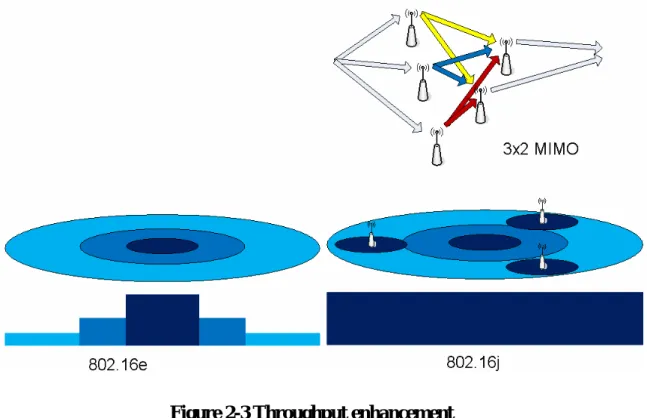
Figure 2.1 is the deployment of relay stations that are installed around the boundary of MR-BS relay the signals between BS and MSs. By specifying the relay stations, the IEEE802.16j mobile multi-hop relay (MMR) provides an attractive solution for the coverage extension and throughput enhancement of IEEE802.16e networks. After RSs are deployed, the Signal to Interference Noise Ratio (SINR) is promoted. Therefore, the higher level of AMC is used to improve the throughput and the MS in the coverage hole or shadow of building can also receive better quality of signals. Coverage extension and throughput enhancement are the two important benefits to the relay station system.
z Coverage extension
Figure 2.2 shows that how relay stations extend cell coverage by transmitting the signal to the MS that may be under the shadow of a building or in the coverage hole. z Throughput enhancement
Figure 2.3 is the illustration that system has higher throughput over multi-hop paths by deploying the relay stations.
Figure 2-1 Relay Station deployment
Two kinds of relay station are defined in multi-hop relay system. One is transparent RS that transfers only data message but not control message such as preamble and MAP as showed in Figure 2-4. The other one is non-transparent RS that transfers both data and its own preamble and MAP to subordinate MSs in Figure 2-5.
2.2 Data/control plane of Relay Station
2.2.1 Network entry and initialization
System shall support the applicable procedures for entering and registering a new SS, RS or a new node to the network. All network entry procedures described hereunder through apply only to Point-to-multipoint (PMP) operation and PMP operation with MR support.
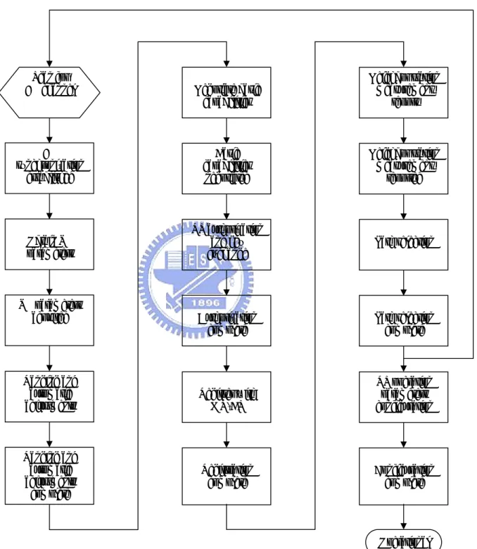
The procedure for initialization for an RS is shown in Figure 2-6. As compared with SS network entry, these stages of IP connectivity establishment, time of day establishment, operational parameters transfer, and connections set up are not required, and for all other stages the RS shall have the same behavior as an SS during network entry.
2.2.1.1 MS network entry procedures in transparent RS systems
During the MS network entry procedures in the transparent RS system, MS scans for DL channel and establishes synchronization with the MR-BS, then obtains the transmission parameters from UCD (UL channel descriptor) message. The network entry procedures shall follow the steps as illustrated in Figure 2-7 and are described as follows.
1. MS scans for DL channel and establish synchronization with the MR-BS.
2. The initial ranging process shall begin by MS sending initial-ranging CDMA codes on the UL allocation dedicated for that process. The RS shall monitor ranging channel assigned by the MR-BS.
3. The code may be received by the MR-BS and some RSs near the MS. RSs receiving the code with sufficient signal quality shall transmit a RNG-REQ to the MR-BS with the RS basic CID.
4. RNG-REQ message contains ranging status, code attributes and adjustment information such as frequency, timing and transmission power.
5. When a RS receives multiple codes in a frame, the RS sends MR-BS a RNG-REQ message which contains information of multiple codes which are received with sufficient signal quality.
6. MR-BS compares measured signal information at each station to decide the most appropriate path to communicate with the code originating MS, according to channel measurement information.
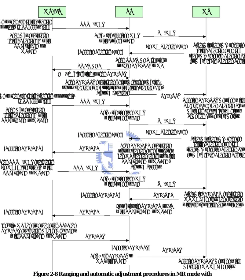
2.2.1.2 MS network entry procedures in non-transparent RS systems
During the MS network entry procedures in non-transparent RS systems, MS scans for DL channel and establishes synchronization with the non-transparent RS, then obtains transmission parameters from UCD (UL channel descriptor) message. There are two scheduling mechanism for MS network entry procedures in non-transparent RS systems.
1. The network entry procedures in non-transparent RS with Centralized scheduling as shown in Figure 2-8.
2. The network entry procedures in non-transparent RS with Distributed scheduling as shown in Figure 2-9.
Figure 2-6 RS initialization overview Scan for DL channel DL synchronization established Obtain UL parameters UL parameters acquired Ranging and automatic adjustments Ranging and automatic adjustments complete Basic capabilities negotiated RS authorization and key exchange Authorization complete Register with MR-BS Registration complete Neighbor station measurement reported Path selection Path selection complete RS operation parameters configuration Configuration complete Negotiate basic capabilities Neighbor station measurement report Operational
Figure 2-7 Ranging and automatic adjustments procedure in transparent mode
Receive Ranging Code Receive Ranging Code
CDMA Ranging Code Time to send the initial
ranging opportunity
MR-BS RS MS
Send map containing Initial Ranging IE
UL-MAP
Transmit randomly selected Initial Ranging code in a randomly selected Ranging Slot from available Ranging Region CDMA Ranging Code
Receive Ranging Code
Wait for RNG-REQ from RSs Send RNG-REQ containing adjustment information, status, ranging code attributes with RS basic CID or MT-CID.
Status = Continue RNG-REQ
RNG-RSP Receive RNG-REQ
Compare channel performance and select the best path. Send RNG-RSP containing adjustment information, status, ranging code attributes with initial ranging CID
Status = Continue
Time to send the initial ranging opportunity Send map containing
Initial Ranging IE
UL-MAP
Receive Ranging Code
Wait for RNG-REQ from RSs Send RNG-REQ containing status, ranging code attributes with RS basic CID or MT-CID.
Status = Success RNG-REQ
RNG-RSP Receive RNG-REQ
Send RNG-RSP containing status, ranging code attributes with initial ranging CID
Status = Success
Receive RNG-RSP message with Ranging Code and Ranging Slot
matching sent values. Adjust Time and Power parameters
Receive RNG-RSP message with Ranging Code and Ranging Slot
matching sent values. UL-MAP
Transmit randomly selected Initial Ranging code in a randomly selected Ranging Slot from available Ranging Region
UL-MAP UL-MAP
Send UL-MAP containing CDMA_Allocation-IE
Transmit RNG-REQ containing MS MAC address and continue with regular Initial network entry RNG-REQ
Receive RNG-REQ
Forwards the RNG-REQ to BS with RS basic CID RNG-REQ
Receive RNG-REQ
Identify MS and its connecting RS. Send RNG-RSP containing management CIDs
with initial ranging CID RNG-RSP
Receive RNG-RSP message with matching MS MAC address
Figure 2-8 Ranging and automatic adjustment procedures in MR mode with centralized scheduling
DL BW allocation to send RNG-RSP [Receive Ranging Code]
CDMA Ranging Code [Time to send the initial ranging
opportunity in RS access link]
MR-BS RS MS
Send map containing Initial Ranging IE with
RS basic CID or MT-CID
RS UL-MAP
Transmit randomly selected Initial Ranging code in a randomly selected Ranging Slot
from available Ranging Region CDMA Ranging Code
Send RNG-RSP containing adjustment information, status, ranging code attributes with initial ranging CID.
Status = Continue RS BR HDR
[Time to send the initial ranging opportunity in RS access link]
Send map containing Initial Ranging IE with RS basic CID or MT-CID
RNG-RSP
Send RNG-REQ containing status, ranging code attributes and MS ranging indicator with RS basic CID or MT-CID.
Status = Success RNG-REQ
[Receive RNG-REQ]
Receive RNG-RSP message with Ranging Code and Ranging Slot
matching sent values. Adjust Time and Power parameters
Transmit randomly selected Initial Ranging code in a randomly selected Ranging Slot
from available Ranging Region
UL-MAP RS UL-MAP
Send RS UL-MAP containing CDMA_Allocation-IE with
RS basic CID or MT-CID
RNG-REQ [Receive RNG-REQ]
Forwards the RNG-REQ to BS with RS basic CID or MT-CID RNG-REQ
[Receive RNG-REQ]
Identify MS and its connecting RS. Send RNG-RSP containing management CIDs
with RS basic CID or MT-CID RNG-RSP
Receive RNG-RSP message with matching MS MAC address UL-MAP
Relay the received MAP with broadcast CID
Send RS BR HDR in order to send RNG-RSP to MS
RS UL-MAP
UL-MAP
[Receive Ranging Code]
Relay the received MAP with broadcast CID Relay the received MAP
with broadcast CID
Transmit RNG-REQ containing MS MAC address and continue with regular Initial network entry
RNG-RSP [Receive RNG-RSP]
Relay the RNG-RSP to MS with IR CID
Figure 2-9 Ranging and automatic adjustment procedures in MR mode with distributed scheduling
Receive Ranging Code
CDMA Ranging Code Time to send the initial
ranging opportunity
MR-BS RS MS
Transmit randomly selected Initial Ranging code in a randomly selected Ranging Slot from available Ranging
Region CDMA Ranging Code
Send RNG-RSP with Time and Power Corrections and original Ranging Code and Ranging Slot.
Status = Continue
Time to send the initial ranging opportunity in RS access link
Send map containing Initial Ranging IE with RS basic CID or MT-CID
RNG-RSP
If status is success in RNG-RSP, send RNG-RSP containing success
status with Initial Ranging CID
Receive RNG-RSP message with Ranging Code and Ranging Slot
matching sent values. Adjust Time and Power parameters
Transmit randomly selected Initial Ranging
code in a randomly selected Ranging Slot from available Ranging
Region
UL-MAP RNG-RSP
Receive RNG-REQ RNG-REQ
Send UL-MAP containing CDMA_Allocation-IE
Identify MS and its connecting RS. Send RNG-RSP containing management CIDs
with initial ranging CID
RNG-RSP
Receive RNG-RSP message with matching MS MAC address UL-MAP
Send map containing Initial Ranging IE
UL-MAP
Receive Ranging Code Status = Success
Transmit RNG-REQ containing MS MAC address
and continue with regular Initial network entry
RNG-RSP Receive RNG-RSP
Relay the RNG-RSP to MS with Initial Ranging CID
Receive RNG-RSP message with Ranging Code and Ranging Slot
matching sent value
RNG-REQ Receive RNG-REQ
If RNG-REQ has Initial Ranging CID and MS ID MAC address, then
RS relays it to BS with RS Basic CID or MT-CID
2.2.1.3 RS grouping
RS grouping method includes the following characteristics.
z A group of RSs forming a virtual RS group is decided by the MR-BS according to some criteria such as potential interference that they cause to each other. The virtual group may include that MR-BS.
z Each RS is assigned an individual unicast RSID and multicast RSID as the RS group ID. All RSs of the same virtual group have the same multicast RSID. These RSs can be managed individually or as a group by these two separate IDs. These IDs are unique to the associated MR-BS.
z If there is an MR-BS within a virtual RS group, all the RSs of this virtual group shall either transmit the same preamble, FCH, and MAP as that of MR-BS. Otherwise they do not transmit any preamble, FCH or MAP. If there is not an MR-BS within the virtual group and one RS of the virtual group is a non-transparent RS, all other RSs shall either transmit the same preamble, FCH or and MAP as that of the non-transparent RS or all of them do not transmit any preamble, FCH and MAP. These RSs share the radio resources for data burst transmission.
z Removal of an RS from the virtual group : During the normal operation of the RS group, each RS continues to monitor the radio environment. When an RS locates at the boundary of the group coverage area, it detects strong interference form other nearby RS or RS group and it can ask to be removed from the RS group.
z Addition of an RS to an existing group or forming a new group : An Rs at the network entry can have some action.
1. Operate on its own. 2. Form a new group. 3. Join an existing group.
The RS can measure the radio signal from the neighbors and report the measurement to MR-BS regarding the preferred preamble index. The MR-BS would reply by either confirming the preamble index selected by the RS or assigning a different one with the corresponding RS group ID.
z Data forwarding within RS group : For DL, the members of an RS group may be configured to forward traffic data for only specific subordinate terminal nodes.
This may be done on a per-terminal or per-transport connection basis. In this way, by specifying scheduling times, two RSs belonging to the same RS group may transmit to two different MSs at the same time. In addition, transmissions may be scheduled such that multiple RSs in the RS group may transmit to the same MS to exploit macro-diversity. This scheduling may be achieved under a centralized scheduling scheme by keeping an MS list or CID list associated with each RS. Each RS would look for the data bound to its subordinate stations or data coming from the subordinate stations in the UL and forward in the assigned times indicated in the MAP. The list may be updated by the RS_Member_List_Update message. If the RS_Member_List_Update message is not provided by the superordinate RS to the RSs members of the RS group, then all RSs members of the group shall transmit according to the MAPs received, without using the per CID transmission.
z For the UL, diversity combining of the information received by the members of RS group can be performed, or the UL signaling can be designed such that several member RSs may receive data from multiple MS at the same time. This scheduling may be achieved under a centralized scheduling scheme by keeping an MS list or CID list associated with each RS and forwarding those messages in a specified resource unit (time and frequency). When the MS is the same and the resources are the same, it is equivalent to macro-diversity. When the resources are the same but the MSs are different, it is equivalent to parallel transmission occurring at different locations.
z Each time a handover occurs or a new terminal joins an RS group, the list of CIDs for the RSs in the group may be updated.
1. MS network entry procedures
Each RS group member shall monitor the CDMA ranging codes from subordinate nodes. If the group parent is not a member of the RS group, then RS group members shall follow the procedure shown in Figure 2-10. If the group parent is a member of the RS group, then the RS group members other than the parent shall follow the procedure shown in Figure 2-10, and the parent (if not MR-BS) shall follow the procedure shown in Figure 2-11 or 2-12.
If the RS is in MS mode of operation, it shall start network entry with the MS network entry procedures as described above. During network entry or normal operation, the MR-BS may configure the RS using RS_Configuration_REQ/RSP messages.
2.2.2 Ranging
A SS or RS shall take the following steps to perform initial ranging:
z After acquiring DL synchronization and UL transmission parameters, the SS/RS shall select one Ranging slot using the random backoff and choose a Ranging Code using a uniform random process. The selected Ranging Code is sent to the BS (as a CDMA code) in the selected Ranging Slot.
z Upon successfully receiving a CDMA ranging code, the BS broadcasts a ranging response message of the received ranging code in the selected ranging slot. The SS/RS uses this response message to adjust its parameters such as time, power and frequency corrections.
z After receiving a ranging response message, the SS/RS shall continue the ranging process as the first entry with ranging codes randomly chosen from the initial ranging domain sent on the periodic ranging region.
z After receiving an initial ranging CDMA code without corrections, the BS shall provide bandwidth allocation for the SS using the CDMA_Allocation_IE to send an RNG-REQ message.
z Initial ranging process is finished after receiving RNG-RSP message with a valid Basic CID. If this RNG-RSP message includes “continue” indication, the ranging process should be continued by the periodic ranging mechanisms.
z The SS should synchronize with the new channel indicated in the RNG-RSP if this message includes an Offset Frequency Adjustment pointing to another channel.
z The timeout for SS/RS to wait for RNG-RSP is defined by T3.
z Using the OFDMA ranging mechanism, the periodic ranging timer is controller by the SS/RS, not the BS.
Only RS should follow the below procedures.
z After receiving UCD message with RS Initial Ranging Code TLV, the RS should use RS Initial Ranging Code not Initial Ranging Code.
z Upon receiving RS Initial Ranging code, the MR-BS may send a RNG-RSP containing “abort” status with preamble indexes of candidate neighbor access stations. The RS shall scan for DL channel of these stations and perform initial ranging.
2.2.2.1 MS periodic ranging and automatic adjustments in
transparent RS systems
The detail procedure is shown as Figure 2-10. The periodic ranging process begins be sending a periodic ranging CDMA codes on the UL allocation dedicated for this purpose. After RSs that are near the MS, these RSs shall transmit a RNG-REQ message with the RS basic CID to the serving MR-BS through the relay path. When receiving ranging code, MR-BS shall wait for RNG-REQ message with the same ranging code attribute from its subordinate RSs for T48 timer. If T48 timer is expired, the MR-BS will compare the measured signal information at each access station to decide adjustment information for RNG-RSP.
2.2.2.2 MS periodic ranging and automatic adjustments in
non-transparent RS systems
As the periodic ranging process of transparent RS systems, that of non-transparent RS systems also shall send a periodic ranging CDMA ranging code on the UL allocation at the beginning. Two kinds of scheduling method, centralized and distributed scheduling, are introduced for the non-transparent RS systems.
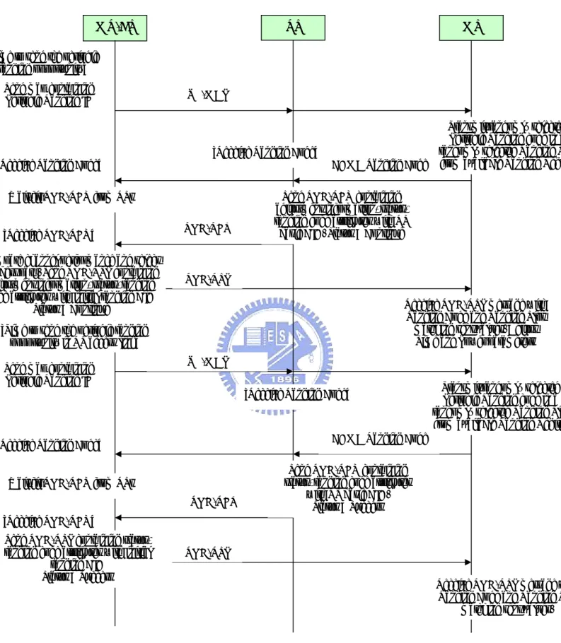
z Non-Transparent RS with Centralized Scheduling
Figure 2-11 introduces the ranging and automatic adjustment procedure in non-transparent RS systems with centralized scheduling. RS shall locally send RNG-RSP to MS on the access link when it receives CDMA ranging code from MS. In order to send RNG-RSP to MS on the access link, RS sends a RS BR header to the MR-BS. After receiving the RS BR header, MR-BS will allocate resources for RNG-RSP and indicate to RS with RS_DL_MAP-IE in DL-MAP.
z
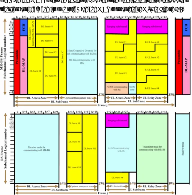
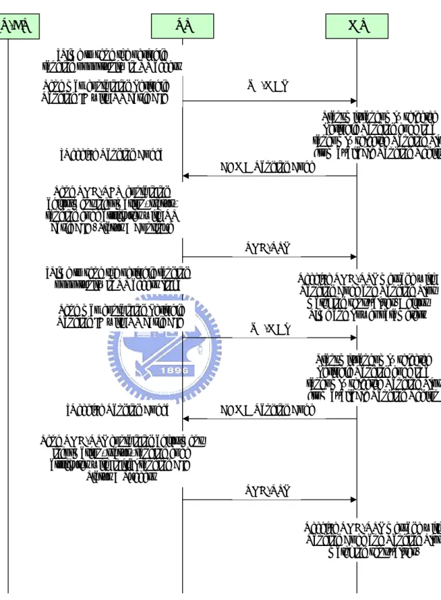
Non-Transparent RS with Distributed SchedulingFigure 2-12 shows the ranging and automatic adjustment procedure in non-transparent RS systems with distributed scheduling.
Figure 2-10 Ranging and automatic adjustment procedure in transparent RS system
MR-BS RS MS
[Time to send the periodic ranging opportunity]
Send map containing
Periodic Ranging IE UL-MAP
Transmit randomly selected Periodic Ranging code in a randomly selected Ranging Slot from available Ranging Region CDMA Ranging Code
[Receive Ranging Code] [Receive Ranging Code]
Wait fir RNG-REQ from RSs Send RNG-REQ containing
adjustment information, status, ranging code attributes with RS basic CID. Status = Continue RNG-REQ
RNG-RSP [Receive RNG-REQ]
Compare channel performance and select the best path. Send RNG-RSP containing adjustment information, status, ranging code attributes with initial ranging CID
Status = Continue
[Time to send the periodic ranging opportunity in RS access link] Send map containing
Periodic Ranging IE
UL-MAP
Transmit randomly selected Periodic Ranging code in a randomly selected Ranging Slot from available Ranging Region CDMA Ranging Code
[Receive Ranging Code]
[Receive Ranging Code]
Wait fir RNG-REQ from RSs
Send RNG-REQ containing status, ranging code attributes
with RS basic CID. Status = Success RNG-REQ
RNG-RSP [Receive RNG-REQ]
Send RNG-RSP containing status, ranging code attributes with initial
ranging CID Status = Success
Receive RNG-RSP message with Ranging Code and Ranging Slot
matching sent values. Adjust Time and Power parameters
Receive RNG-RSP message with Ranging Code and Ranging Slot
Figure 2-11 Ranging and automatic adjustment procedure in non-transparent RS system with centralized scheduling
MR-BS RS MS
[Time to send the periodic ranging opportunity in RS access link]
Send map containing Periodic Ranging IE with RS basic CID
RS UL-MAP
CDMA Ranging Code [Receive Ranging Code]
DL BW allocation to send RNG-RSP
RNG-RSP [Time to send the periodic ranging
opportunity in RS access link]
Send map containing Periodic Ranging IE with RS basic CID
RS UL-MAP
CDMA Ranging Code Relay the received MAP
with broadcast CID
[Receive Ranging Code]
May send RS BR HDR in order to send RNG-RSP to MS
Status = Success RS BR header
RNG-RSP Send RNG-RSP containing status,
ranging code attributes with initial ranging CID
Status = Success
Receive RNG-RSP message with Ranging Code and Ranging Slot
matching sent values. Adjust Time and Power parameters
Receive RNG-RSP message with Ranging Code and Ranging Slot
matching sent values. Relay the received MAP with
broadcast CID
Transmit randomly selected Periodic Ranging code in a randomly selected Ranging Slot
from available Ranging Region May send RS BR HDR in order
to send RNG-RSP to MS Status = Continue RS BR header
Send RNG-REQ containing adjustment information, status, ranging code attributes with RS basic CID. Status = Continue
UL-MAP
Transmit randomly selected Periodic Ranging code in a randomly selected Ranging
Slot from available Ranging Region
DL BW allocation to send RNG-RSP
Figure 2-12 Ranging and automatic adjustment procedure in non-transparent RS system with distributed scheduling
MR-BS RS MS
[Time to send the periodic ranging opportunity in RS access Send map containing Periodic
Ranging IE with RS basic CID UL-MAP
Transmit randomly selected Periodic Ranging code in a randomly selected Ranging Slot
from available Ranging Region CDMA Ranging Code
[Receive Ranging Code]
Send RNG-REQ containing adjustment information, status, ranging code attributes with RS basic CID. Status = Continue
RNG-RSP [Time to send the periodic ranging
opportunity in RS access link] Send map containing Periodic Ranging IE with RS basic CID
UL-MAP
Transmit randomly selected Periodic Ranging code in a randomly selected Ranging Slot
from available Ranging Region CDMA Ranging Code
[Receive Ranging Code]
RNG-RSP Send RNG-RSP containing adjustment
information, status, ranging code attributes with initial ranging CID
Status = Success
Receive RNG-RSP message with Ranging Code and Ranging Slot
matching sent values. Adjust Time and Power parameters
Receive RNG-RSP message with Ranging Code and Ranging Slot
2.2.3 Relay path management and routing
Based on the topology information obtained from topology discovery or update process, MR-BS makes centralized calculation for the path between MR-BS and an access RS for both UL and DL direction. The path creation is subject to the constraints such as the availability of radio resource, radio quality of the link, load condition of an RS, etc. Either embedded path management or explicit path management may be used.
z Embedded Path Management for Relay
When the systematic CID allocation is used, the MR-BS shall update the CID range assigned to its subordinate RSs via the CID_ALLOC-IND message. z Explicit Path Management for Relay
After MR-BS discovers the topology between a newly attached MS or RS and itself, or detects a topology update due to events such as mobility, MR-BS may remove an old path, establish a new path and inform the new path information to all the RSs on the path. When connections are established or removed, MR-BS may distribute the mapping information between the connection and the path to all the RSs on the path. The connection could be a regular connection established for a MS or a connection established for a RS (e.g., basic/primary management CID and tunnel connection).
2.2.4 Relay station neighborhood discovery
During the RS neighbor discovery procedure, the potential RS can obtain its neighbor information during PHY synchronization before initial ranging. Therefore, it can send the report to MR-BS after RNG-REQ, SBC-REQ or REG-REQ. Then the RS sends a RS_NBR-MEAS-REP message back to the MR-BS to response the measurement report.
When a RS is newly deployed into a MR network, it can act as a SS/MS and scan the preamble transmitted by the existing stations before network entry. The RS can report its neighbor discovery and measurement results to MR-BS by RS_NBR-MEAS-REP. The neighboring station list may be instructed by MR_NBR-INFO. Because not every RS will transmit its own preamble and the existing RSs in MR network need to perform measurement over the new RS, MR-BS can instruct the RSs to perform complete neighborhood discovery.
There are two methods to carry out neighborhood measurements. One method is to use the repeatable R-amble transmission and monitoring method. After that the measurements can be sent to the MR-BS by the message RS_NBR-MEAS-REP or any other appropriate measurement report messages. The other method for measurement is to use a pre-planned scheme which is described below.
z The MR-BS sends the RS_Config-REQ message to the RSs which will be involved in the neighborhood discovery mechanism, and the message is either sent by the broadcast, multicast or unicast CID for these RSs. The 8 LSB bits of frame number shall be set to instruct the the starting time to the RSs. If the RSs involved in this mechanism are in different MR-cell, each of the Start Frame Number sent by different MR-BSs shall synchronize to the same frame time. The Prefix shall be set “00” and attach the transmit/receive pattern for each iteration. z The stations follow the instruction to transmit/receive the R-amble at the
designated frames in each iteration.
z The RSs report the RSSI or CINR with corresponding amble index by RS_NBR-MEAS-REP to MR-BS.
2.2.5 Interference measurement for MR
Interference prediction is a measurement and reporting method with supported messaging mechanism to estimate the interference level in MR network. In order to predict the interference or SINR of the radio links for different MR- network topology and radio resource reuse pattern, the following prediction method may be considered based on the RSSI reported by RS_NBR-MEAS-REP message.
1. Prediction of the interference plus noise power received by node #i : The interference plus noise may be the summation of (1) the thermal noise plus background interference power received by node #i and (2) the signal power not intended to be received by node #i but transmitted by the same radio resource. 2. Prediction of the received SINR of node #i : The SINR may be the ratio of “the
total signal power destined to node #i” to “the interference plus noise power obtained in Step 1”.
2.2.6 Messages and data relaying
A non-transparent RS shall broadcast FCH, DCD, UCD, DL-MAP and UL-MAP messages in the DL access zone. In addition, a non-transparent RS shall also broadcast R-FCH, DCD, UCD, and R-MAP messages in the DL relay zone in the case of more than two hops. When the messages are generated by the MR-BS, the MR-BS should send DCD and UCD messages for RS to broadcast on the access link and relay link with RS primary management CID.
Under centralized scheduling, the MR-BS shall generate and send RS-Access-MAP message to RS over RS basic connection once per frame. When RS receives RS-Access-MAP message, RS shall compose FCH and possibly the associated MAPs such as DL/UL-MAP message, Compressed DL/UL-MAP, SUB-DL-UL-MAPs message and HARQ MAP message, etc., based on the RS-Access-MAP message. If the information to compose DL-MAP and UL-MAP messages is not included in RS-Access-MAP, the MR-BS shall send DL-MAP and UL-MAP messages with RS basic CID to the RS directly. In case of more than two hops, the MR-BS shall generate and send RS-RLY-MAP message to RS over RS basic connection once per frame. When RS receives RS-RLY-MAP message, RS shall compose R-FCH and R-MAP based on the RS-RLY-MAP message.
Upon receiving the DCD/UCD message with RS primary CID, as show in Figure 2-13, the RS shall acknowledge the reception of DCD or UCD message over primary management connection by sending an acknowledgment header. The Transaction ID of the ACK header shall be sent to the Configuration Change Count of DCD or UCD message. There shall be one ACK header per message. The RS may retransmit DCD/UCD message if the acknowledgement header is not received at the expiration of T52 timer.
Under centralized scheduling, as shown in Figure 2-14, the RS should request bandwidth on the access link to broadcast the DCD/UCD message with fragmentable broadcast CID.
Under distributed scheduling, the RS shall autonomously broadcast DCD/UCD with fragmentable broadcast CID.
Figure 2-13 Relaying DCD/UCD procedure
Figure 2-14 DCD/UCD broadcasting with centralized scheduling
Serving MR-BS Access RS MS
Send map with broadcast CID
Send DCD or UCD with RS primary CID
R-MAP
DCD or UCD
Send Acknowledgment header containing DCD or UCD message type and Transaction ID as the 8-bit
LSB DCD or UCD count [Receive DCD or UCD]
Acknowledgment header
Serving MR-BS Access RS MS
Send RS BR header in order to send DCD or UCD message RS BR header
RS BW-ALLOC IE
Send DCD or UCD containing network topology with fragmentable
broadcast CID
Send MAP with broadcast CID UL-MAP
DCD or UCD
Receive DCD or UCD with fragmentable broadcast CID
2.2.7 RS service end
In MR networks, an RS may end its service and be removed from the networks. During RS service-end process, all subordinate MSs of the RS should be transferred to another RS or MR-BS prior to RS deregistration. An RS shall transmit DREG-REQ to an MR-BS so that it initiates service-end procedure and requests handover of all its subordinate MS’s. Upon receiving DREG-REQ, the MR-BS decides whether it allows the RS service-end. If the request is accepted, the MR-BS may transmit DREG-CMD to inform the acceptance and start BS-initiated handover process for the requested MSs. After handover procedures between the MR-BS and its subordinate MSs are completed, the MR-BS informs the RS that handover is completed by transmitting DREG-CMD. Upon receiving DREG-CMD, the RS starts deregistration process.
If the MR-BS rejects the request, the MR-BS informs the RS rejection of the request by transmitting DREG-CMD. Upon receiving DREG-CMD with rejection information, the RS continues normal operation. After REQ-duration expires, the RS retransmits DREG-REQ to the MR-BS.
Chapter 3
Handover Procedure and Problem Statement
In order to realize the handover process, the handover procedure of 802.16e is introduced in the first part. The MAC layer handover procedure overview, association procedure, the detail of each process step, and the fast switch mechanism are described.
In the second part, the handover procedure for relay station system is introduced. This part describes the differences of the MAC layer handover procedure between 802.16e and 802.16j. Next, several MS handover situations are discussed.
In the final part, the problem of MS handover in MR network is discussed and the method to solve the problem is proposed.
3.1 Introduction of MAC layer handover procedure in 802.16e
An MS shall be capable of performing handover using the procedures described in this chapter. There may be some situations to trigger the handover procedure. Two examples are as follows:
z When the MS moves to some locations and affected by the signal fading, interference levels, etc., the MS needs to change the BS to another BS which has better connection in order to provide a higher signal quality. z When the MS can be served by higher QoS at another BS, the MS changes
the access BS to obtain higher QoS.
3.1.1 Network topology acquisition
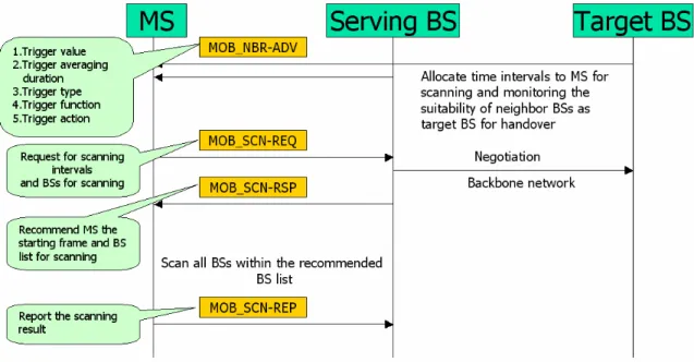
A BS uses MOB_NBR-ADV message to broadcast its information of the network topology. The MOB_NBR-ADV provides channel information for neighboring BSs normally provided by each BS’s own DCD (DL channel descriptor)/UCD (UL channel descriptor) message transmissions. Some BSs may obtain this information from the backbone network.
Figure 3-1 shows that MS scans neighbor BSs and obtains the network topology from the MOB_NBR-ADV broadcasted by the BSs. The MOB_NBR-ADV sent by BS includes the trigger information such as trigger value, trigger averaging duration, trigger type, trigger function, and trigger action. A BS may allocate time intervals to MS for scanning and monitoring the suitability of neighbor BSs as target BS for handover. By using the MOB_SCN-REQ message, an MS may request an allocation of a group of scanning intervals by interleaving the normal operation and recommend a starting frame of the first scanning interval. In the MOB_SCN-REQ message, the MS shall indicate group of neighbor BSs for which only Scanning or Scanning with Association are requested by MS. Upon receiving the MOB_SCN-REQ messages, the serving BS may response the MOB_SCN-RSP message to recommend MS the starting frame. In the MOB_SCN_RSP message, the BS shall indicate this information recommended by BS. After receiving the MOB_SCN-RSP message, the MS shall scan all BSs within the Recommended BS list of the message and then report the scanning result with the MOB_SCN-REP message as conditioned by a specified trigger event.
Figure 3-1 MS scanning of neighbor BSs
3.1.2 Association procedure
Association is an optional initial ranging procedure occurring scanning interval with respect to one of the neighbor BSs. There are three levels of association :
z Association Level 0 : Scan / Association without coordination
As shown in Figure 3-2, the serving BS and the MS negotiate about the association duration and intervals by using MOB_SCN-REQ and MOB_SCN-RSP with scanning type = 0b001. The serving BS provides periodic intervals where the MS may range neighboring BSs. An MS chooses a ranging code from the initial ranging domain of the target BS and transmits it in the contention-based ranging interval of the target BS.
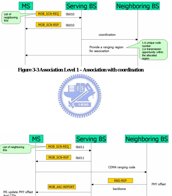
z Association Level 1 : Association with coordination
As shown in Figure 3-3, the serving BS provides association parameters to the MS and coordinates association between the MS and neighboring BSs. The MS may request association with coordination by sending the MOB_SCN-REQ message to the serving BS with scanning type = 0b010. This message may include a list of neighboring BSs that the MS wishes to
perform association with. The serving BS may response to the MS’s request by sending the MOB_SCN-RSP message.
z Association Level 2 : Network assisted association reporting
As shown in Figure 3-4, the MS may request the association with network assisted association reporting by sending the MOB_SCN-REQ message to the serving BS with scanning type = 0b011. The list of neighboring BSs that the MS wants to perform association with may be included in this message. After receiving this message, the serving BS will coordinate the association procedure with the requested neighboring BSs in a process similar to the association level 1. In this association type, the MS only transmits the CDMA ranging code and does not wait for RNG-RSP message.
Figure 3-3 Association Level 1 – Association with coordination
3.1.3 Handover Process
This section defines the handover process in which an MS migrates from the air-interface provided by one BS to the air-interface provided by another BS. The following stages are included in the handover process.
z Cell reselection – Figure 3-5 shows this stage that MS may use the MOB_NBR-ADV message to obtain the neighbor BS information and make a request to schedule scanning intervals or sleep intervals to scan, and possibly range, neighbor BSs for the purpose of evaluating MS interest in handover to a potential target BS.
z Handover decision and initiation – An Handover Process begins for an MS to handover from the serving to a target BS by a decision made by either the MS or the serving BS. The Handover decision may be initiated by MOB_MSHO-REQ from MS or MOB_BSHO-REQ from BS. MS may evaluate the possible target BS and report it to BS. MS may decide to handover to a different BS that may or may not be in the MOB_BSHO-RSP message. Figure 3-6 shows this handover stage.
Figure 3-6 Handover Decision and Initiation
z Network Re-entry – Synchronization and Ranging – The MS shall synchronize to the DL transmissions of the Target BS and obtain DL and UL transmission parameters. If the MS had previously received a MOB_NBR-ADV message including Target BSID, Physical Frequency, DCD and UCD, this stage may be shortened. If the Target BS had previously received Handover notification from the Serving BS over the backbone network, then the Target BS may allocate one or more non-contention-based initial ranging opportunities. Upon receiving MS RNG-REQ message including serving BSID, the target BS may send a request to serving BS for the information of MS over the backbone network and the serving BS may respond. As indicated in the Handover Optimization TLV (type/length/value) settings, the target BS may select to use MS service and operational information obtained over the backbone network to build and send unsolicited SBC-RSP (SS basic capability response) or REG-RSP (registration response) management messages to update MS operational information, or to include this information into TLV items in the RNG-RSP. The detail flow is as shown in Figure 3-7.
Figure 3-7 Network Re-entry – Synchronization and Ranging
z Handover cancellation – Although an MS or BS has initiated a Handover procedure by using either MOB_MSHO-REQ or MOB_BSHO-REQ message, the MS may cancel the handover procedure at any time by sending the MOB_HO-IND message with HO_IND_type = 0b01.
z Termination with the serving BS – After the Handover request and response handshake has completed, the MS may begin the actual handover process. At the some stages described above during the handover process, the MS terminates service with the original serving BS by sending a MOB_HO-IND message with the HO_IND_type value indicating which serving to be released.
3.2 Introduction of MAC layer handover procedure in 802.16j
The MS’s MAC layer handover procedure in 802.16j is the same as the procedure defined in 802.16e. In this section, the MAC layer handover procedure related to relay station shall be discussed. There may be some situations to trigger the handover procedure. Two examples are as follows:
z When the MS moves to some locations and affected by the signal fading, interference levels, etc., the MS needs to change the RS/BS to another RS/BS which has better connection in order to provide a higher signal quality.
z When the MS can be serviced with higher QoS at another RS/BS, the MS changes the access RS/BS to obtain higher QoS
3.2.1 Network topology acquisition
The MR-BS and the RS shall broadcast the MOB_NBR-ADV message including the information about the infrastructure stations and this information may be obtained over the backbone network or over the relay links. Each non-transparent RS can broadcast its MOB_NBR-ADV message for its service area. For transparent RS, the MOB_NBR-ADV message shall be broadcasted by the MR-BS. There are two methods to generate the MOB_NBR-ADV message for an RS.
z Broadcast the MOB_NBR-ADV message without modifying the neighbor list of the MR_NBR-INFO message received from the MR-BS.
z Customize and compose a MOB_NBR-ADV message by utilizing the information present in the MR_NBR-INFO message as well as any additional information that the RS itself may have obtained, for instance, by scanning and measurement.
3.2.1.1 MS scanning of neighbor BSs
MR-BS shall control MS scanning of neighbor BSs in MR network. An RS relays MOB_SCN-REQ, MOB_SCN-RSP and MOB_SCN-REP messages between an MS and the MR-BS in centralized scheduling or distributed scheduling. The procedure of MS scanning is shown as Figure 3-8.
Figure 3-8 MS scanning of neighbor BSs
3.2.2 Association procedure in an MR network
3.2.2.1 Association parameter acquisition
If the serving MR-BS decides to recommend the MS to scan its neighbor stations with association level 1 or 2 in a MR system with distributed scheduling, it obtain the association parameters available from the MS’s neighbor stations before send the MOB_SCN-RSP message. If this neighbor stations is located in a different MR-cells from the MS, the MS’s serving MR-BS shall send a message via the backbone network to the MR-BS of the neighbor stations to obtain the association parameters. In the case that this neighbor station is an RS, its serving MR-BS must forward an MR_ASC-REQ message to the RS to request to forward its association parameters using MR_ASC-RSP message. This procedure is shown as Figure 3-9.
If the neighbor station is an RS in the same MR-cells as the MS, the serving MR-BS shall directly request the RS for the association parameters using MR_ASC-REQ message.
If the allocated association level is 1 or 2, the MR_ASC-RSP message sent by the RS should include the association parameters such as Rendezvous time, CDMA code, and Transmission opportunity offset.
After receiving these association parameters, the MR-BS should forward this information to the MS via MOB_SCN-RSP if these information satisfy the MS’s
Figure 3-9 Association parameter acquisition for different MR-cell
3.2.2.2 Association level 0 and 1
As shown in Figure 3-10, upon successfully receiving a ranging code from a scanning MS, the neighbor station shall provide an UL allocation for the MS to transmit an RNG-REQ message including Serving BS ID and MS MAC address. If the neighbor station is an RS, is shall forward the RNG-REQ message to its MR-BS and the MR-Bs shall respond an RNG-RSP message for the RS to forward to the MS.
3.2.2.3 Association level 2
While using association level 2, the scanning MS shall transmit a CDMA ranging code to the neighbor station. The neighbor station shall send the RNG-RSP message to its serving MR-BS instead of the MS. If the MR-BS is not the serving MR-BS of the MS, it shall send the RNG-RSP message to the MS’s serving MR-BS via the backbone network. The MS’s MR-Bs shall generate a single MOB_ASC-REP message from all RNG-RSP information of all of the MS’s neighbor station. This message flow is shown as Figure 3-11.
Figure 3-10 Association level 0 and 1
3.2.3 Handover process
The handover process of 802.16j is almost the same as that of 802.16e for the MS part so in this section, the difference between these two handover process is discussed.
MR-BS shall control handover process in centralized control MR network. An RS shall relay the handover associated messages between the MS and the MR-BS both in centralized scheduling and distributed scheduling.
3.2.4 Mobile relay station handover
In this section, the Relay Station Handover process is defined as Figure 3-12. An relay station migrates from the air-interface provided by one access station to the air-interface by another access station. This RS handover process includes the same stages as those defined for the MS handover process with the following additional stages.
z Path selection. Enable the target MR-BS to indicate a path reselection. The target MR-BS may skip this stage if the bit#0 in RS HO optimization TLV of RNG-RSP is set.
z RS operational parameter configuration. Enable the target MR-BS to reconfigure RS operational parameters. If the bit #1 in RS HO optimization TLV of RNG-RSP is set, the target MR-BS may skip this stage.
z Transport/tunnel connection re-establishment. Enable the target MR-BS to re-establish transport/tunnel connection for an RS. If the bit #2 in RS HO optimization TLV of RNG-RSP is set, the target MR-BS may skip this stage. z MS CID update. Re-establish the connection between the child MSs and the
target MR-BS if the MS handover procedure is not invoked between the MS and the target MR-BS. If the MS handover procedure is invoked, this stage shall be skipped. MS CID update is only needed if the MS CID based data forwarding scheme is used and a CID of a child MS collides with the CID of another MS served by the target MR-BS. Then the MR-BS informs the RS to perform the MS handover procedure regarding the new CIDs if its child MSs.
Figure 3-12 Relay Station Handover Procedure RS operation (Cell selection by scan RS-amble) HO decision Downlink Synch Established Obtain UL parameters
Obtain Target Station UL Parameters Uplink Parameters Acquired Ranging & Automatic Adjustments with Target Station Basic Capabilities Negotiated RS Authorization and Key Exchange
RS Authorization Complete RS Registration with MR-BS Registration Complete RS Operational Parameter Configuration Complete Transport/tunnel Connection Re-establishment Transport/tunnel Connection Re-establishment Complete MS CID update MS CID Update Complete Negotiate Basic Capabilities RS Operational Parameters Configuration
Scan for Target Station Downlink Channel Ranging & Automatic Adjustments Complete Path Selection Path Selection Complete
3.2.5 MS handover procedure involving RS
An MS, connected through an RS or MR-BS, shall follow the same handover procedure as described for an MS handover procedure.
3.2.5.1 MS movement among access stations with different preamble/FCH/MAP
The Relay Station shall relay Handover management messages between MS and MR-BS. If the serving MR-Bs knows that the MS handovers to a new access station or the Resource retain timer expires, and the MS’s old access station is an RS under the control of the MR-BS, the MR-BS shall send the MS_INFO-DEL message to the RS discard MS context information. After receiving the MS_INFO-DEL message, the RS shall respond the MS_DEL-ACK message to the MR-BS. This flow is shown as Figure 3-13.
Figure 3-13 Handover procedure involving RS with centralized HO control from MR-BS
3.2.5.2 MS movement among access stations with same preamble/FCH/MAP
In this case that all access stations use the same preamble/FCH/MAP like RS virtual group, the MS is not aware of the handover. Therefore, the RS and MR-BS shall assist MS movement among stations using the same preamble/FCH/MAP by performing measurement of the MS signal quality. The stations sharing the same
preamble/FCH/MAP shall measure the signal quality (RSSI, CINR) and the Timing Adjust (TA) for each active MS served by these stations to support MS mobility among these stations. All RSs shall use the MOB_RSSCN-REP message to provide the MR-BS the report metrics (RSSI, CINR, and TA) for each active MS. There are two reporting modes supported by RSs described as the following sections. Upon receiving the report, the MR-BS shall select the target RS and use RNG-RSP to adjust the timing and the power level of the MS to finish the handover procedure.
z Mode 1
In this mode, only the access RS shall automatically report its measurement result to MR-BS in an event-triggered or periodic way. The MR-BS shall send the MOB_RSSCN-RSP message to request all or part of RSs of the same RS virtual group to report their measurement result for a specific MS. For event-triggered reporting, if the power, CINR, or timing requirement for the specific MS is not satisfied, the access RS shall report it to the MR-BS. For periodic reporting, the access shall send the measurement result by the MOB_RSSCN-REP message every REP_INT interval.
z Mode 2
In this mode, all RSs including access RS and non-access RSs in the same RS virtual group shall automatically the measurement result by the MOB_RSSCN-REP message to the MR-BS in an event-triggered or periodic way. The condition of the event-triggered and periodic way is the same as that of mode 1.
3.2.6 MS MAC handover procedure in a MR network
The 802.16j MAC handover procedure [3] need to enable an 802.16e compliant MS to handover seamlessly in a MR network following the MAC handover procedure defined in P802.16Rev2/D2 [2]. Figure 3-14 depicts the seven handover cases that are classified into two type.
z Intra-MR-BS handover: The MR-BS sends the RNG_RSP message to the given MS for power level, timing advance adjustment to MS adapt to the target access station.
station is a RS in the same MR cell.
2. Case 2: The current access station is a RS and the target station is a serving MR-BS. The current station and the target station are in the same MR cell.
3. Case 3: The current access station is a RS and the target access station is another RS in the same MR cell.
There is an issue that will be discussed in the following sections.
Path reselection issue: The proposed method is to reduce the unnecessary handover (Ping-Pong Effect) with MS’s fast mobility. z Inter-MR-BS handover: The legacy 802.16e handover procedures can be
reused in these cases.
1. Case 4: The current access station is a MR-BS and the target access station is another MR-BS in the different MR cell.
2. Case 5: The current access station is a MR-BS and the target access station is a RS in a different MR cell.
3. Case 6: The current access station is a RS and the target access station is a MR-BS in a different MR cell.
4. Case 7: The current access station is a RS and the target access station is another RS in a different MR cell.
In this type of handover, the conclusion is as below.
MS shall conduct 802.16e compliant handover procedures for backward compatibility.
MS can sense the handover procedure, so the legacy 802.16e handover mechanism can be reused.