article is dedicated to the late Steve Carr. who taught the author many practicalities of LNA design.
REFERENCES
1. S. Vaughn, K. White. U . K. Mishra, M. J . Delaney. P. Greiling. and S. Rosenbaum. "High Performance V-Band Low Noise Am- plifiers." I989 IEEE MTT-S Symp. Digest. pp. 801-804. 2. K. H. G. Duh. P. C. Chao. P. Ho, A. Tessmer, S. M. J . Liu, M.
Y. Kao. P. M. Smith. and J . M. Ballingall, "W-Band InGaAs HEMT Low Noise Amplifiers," 1990 IEEE MTT-S Symp. Digest, 3. E. D . Archer and Y. I . Ryu, "Ka/Q-Band Broadband, Ka and W-Band Low Noise HEMT Amplifiers," 1989 IEEE Military Commun. Conf.. pp. 735-738.
4. U . K. Mishra, A. S. Brown, M. J . Delaney. P. T. Greiling, and
C . F. Krumm. "The AIInAs-GaInAs HEMT for Microwave and Millimeter-Wave Applications," IEEE Trans. Microwave Theory Tech., Vol. MTT-37. No. 9. Sept. 1989, pp. 1279-1285. pp. 595-598.
5. M. J . Delaney. private communication.
6. M. S. Gupta, 0. Pitzalis, J r . . S . E. Rosenbaum, and P. T. Greiling. "Microwave Noise Characterization of GaAs MESFETs: Evalu- ation by On-Wafer Low-Frequency Output Noise Current Mea- surement." IEEE Trans. Microwave Theory Tech., Vol. MTT-35, No. 12. Dec. 1987. pp. 1208-1281.
7. M. W. Pospieszalski. "Modeling of Noise Parameters of MES- FET's and MODFETs and Their Frequency and Temperature Dependence" IEEE Trans. Microwave Theory Tech., Vol M I T - 37. No. 9, Sept. 1989, pp. 1340-1350.
Received 8-1-91 Microwave and Optical Technology Letters. 51 1, 1-4
0 1992 John Wiley & Sons, Inc. CCC O8%-2477192/$4.00
ABSTRACT
The mixed transmission of digital and analog signals via single- mode fiber has potential in future fiber-optic systems. We have stud- ied the effect of chirping of the baseband digital signal on the analog subcarrier channels using computer simulation. I f the location of the subcarriers or the bias of the laser is selected properly, the S N R penalty due to chirping and cross talk will be less than 0.5 dB. INTRODUCTION
For short-haul application, it may be more convenient and cost effective to integrate a high-bit-rate digital datalvoice system with an analog video system using existing fiber-optic system facilities [l, 21. The simultaneous transmission of an optical subcarrier with a baseband digital signal is also re- ported in [3. 41. For high-bit-rate application, the direct cur- rent modulation of laser diode causes a dynamic shift of the peak emission wavelength [5], and thus the subcarrier chan- nels are much affected by the digital data. Since the baseband digital service is little affected by the optical subcarriers [l- 41. in this article we study only the effect of the digital data on the optical subcarriers with FM-TV signals.
The schematic diagram is shown in Figure 1 with a base- band digital data stream and subcarrier FM-TV signal [l, 21. In low-bit-rate applications [3, 41, the effect of chirping will not be serious. In high-bit-rate application, the subcarriers have been proposed to be located at the node point 2Rb ( R ,
is the baseband bit rate) [ l , 21, but the effect of chirping may affect the subcarriers seriously.
SIMULATION
To investigate the effect of chirping on the subcarrier channel, we used a simulation technique [6, 71 which numerically in- tegrates the well-known single-mode laser rate equations:
THE
EFFECT OF LASER CHIRPING ON
OPTICAL SUBCARRIER MULTIPLEXED
BASEBAND SIGNAL
SYSTEM WITH HIGH-BIT-RATE
Hen-Wai Tsao, Keang-Po Ho, and Yang-Han Lee Department of Electrical EngineeringNationai Taiwan University Taipei Taiwan 10764 KEY TERMS
Optical communications, subcarriers multiplexed system, laser chirping
N
channel
F M - T Vdigital d a t a
where the spontaneous recombination and photon absorption are represented by phenomenological carrier and photon life- times (r,,, T ~ ) , respectively, and where the saturation of the differential optical gain (8,) is represented by a linear term, (1
+
E S ) ; n, is the electron excess density andS
is the photon density, respectively; N , is the electron density at transpar-J
Combiner
. I
Figure 1
insert graph is the spectrum at the input
Schematic diagram of the lightwave communication system with baseband digital data stream and optical subcarriers. The
6
5
4
2
1
0
nE
a
a
I I I I i1.Z0.4
0.6
0.8
1
1.2
1.4
'Time
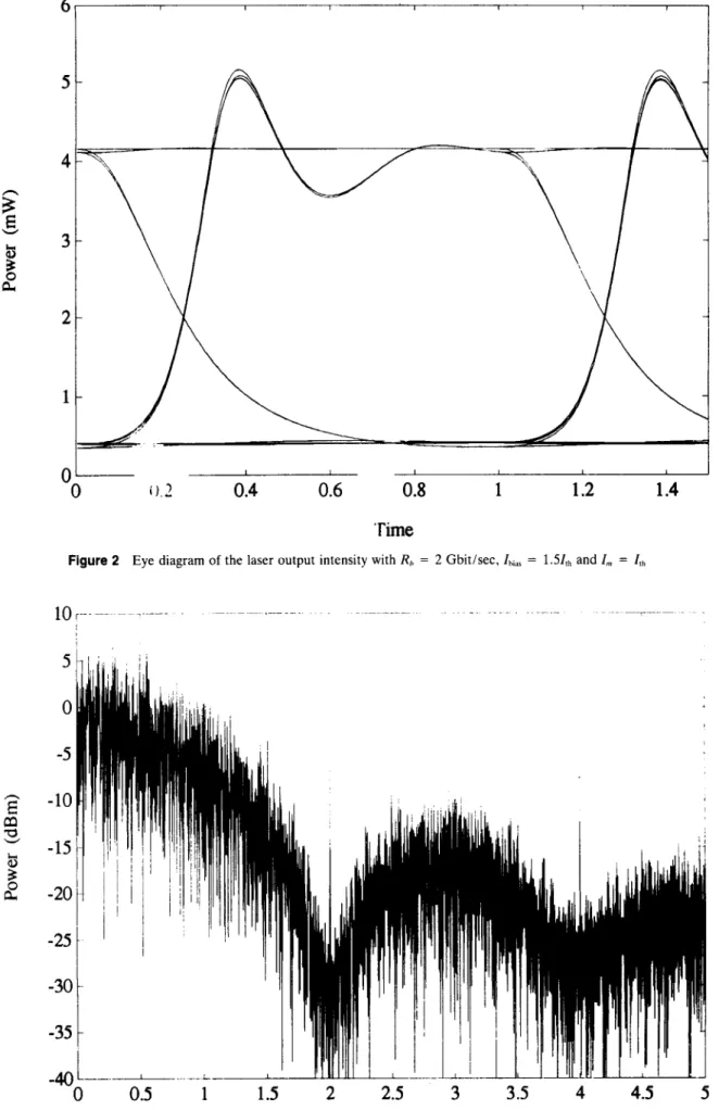
Figure 2 Eye diagram of the laser output intensity with Rh = 2 Gbit/sec, I,,,, = 1.51,h and I, = I,,
5
0
-5
-10
-15
-20
-25
-30
-35
0
0.5
1
1.5
2
2.5
3
3.5
4
4.5
5
Frequency (GHz)
7"Figure 3 The spectrum of the laser output intensity with parameter the Same as Figure 2
ency. V,,,, is the volume of the active layer, j? is the spontaneous emission coupling constant, I is the injection current, e is the electron charge, and
r
is the photon confinement factor. Laser parasitics and intentional transmitter filtering are accounted for by a single-pole RC prefiltering of the injection current.Our simulation uses the laser parameters given in [ 7 ] . with the injection current of the laser as
b C
where I,,,, is the dc bias current, I,,, is the height of the current pulse. a, is the binary data (0.
+
1). and p ( t ) is the current pulse [6. 71. The rise time of the injection current is 100 ps. With R,, = 2 Gbitisec. Ihlr, = l . S f l h with I,, = eVdLlNJ7,, [8]. we find the eye pattern of the output of the laser as Figure 2and the spectrum of the baseband signal as Figure 3. We can see that at the node point (2R,). there is a tone induced by
chirping. This side tone will affect seriously the system such
-
240MHz 1 0 . 5 0 6 - 2 0 - 2 5 - 3 0 - 3 5-
40 -45- 5 0
as [ l , 21 because the subcarriers are just located near this tone.
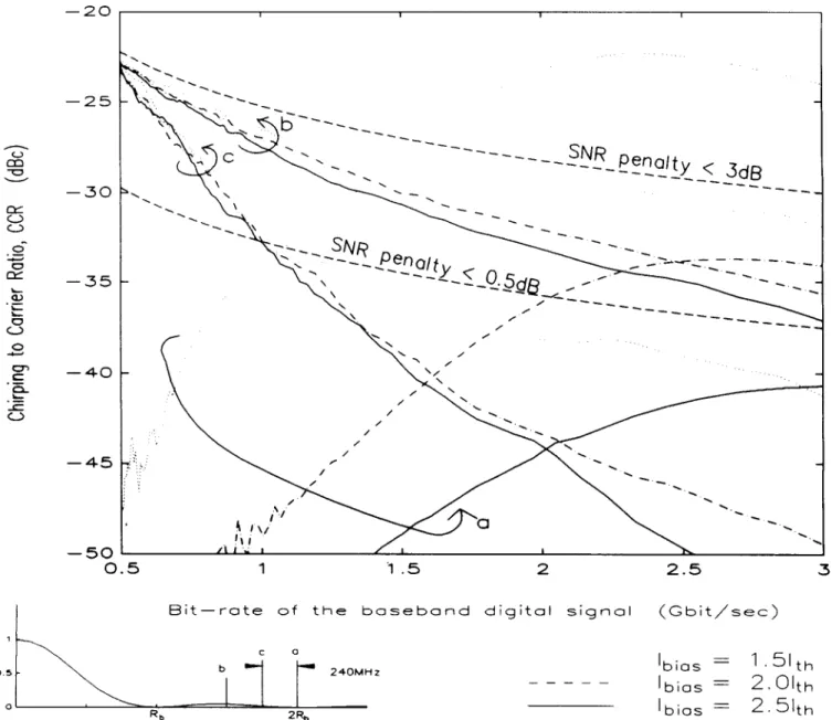
The subcarriers are FM-TV signal with a bandwidth of 30 MHz. We can find the power contained in the 30-MHz band by using fast Fourier transform. We define the chirping-to- carrier ratio (CCR) as P,lP,,,, with P, the total chirping and cross-talk power resulting from the digital channel that falls to the FM-TV band, and PdlB the ac power of the digital channel. Figure 4 is the simulated CCR a t three different bias currents. Three curves are the C C R of the channel centered at ( a ) the node point 2R,; (b) the peak of the sideband 1.5 R,; (c) 2R, - 240 MHz, which is corresponding to the first channel of a 10-channel FM-TV signal centered at 2Rh. As
the bit rate increases, the C C R in the node point is even worse than the C C R a t the secondary peak.
Also shown in Figure 4 are the C C R curves below which the degradation of signal-to-noise ratio (SNR) are less than 3 and 0.5 d B , respectively. If there is only white Gaussian noise, the S N R of digital channel or carrier-to-noise ratio
I I 1 I
.
0.5 1 i .5 2 2.5 3
B i t - r a t e o f t h e b a s e b a n d d i g i t a l s i g n a l ( G b i t / s e c )
Figure 4 The CCR versus modulation bit rate with difference bias current. Below the dashed lines are the required CCR to achieve simultaneously a ;' = 16.5 dB for analog channels and a ;' = 6 for digital signals with a SNR penalty of less than 3 or 0.5 dB. respectively
(CNR) of analog channel is 7 = P / N , , B , with P the signal
(carrier) power. N(, the noise spectrum density, and B the bandwidth. For FM-TV signal, y = 16.5 d B is necessary to achieve an SNR of 56 d B [9]. For a digital channel, 1’ = 6 is necessary to achieve a bit error rate (BER) of less than lo-’ [lo]. To achieve a 7 = 16.5 dB for an analog channel and y = 6 for a digital signal simultaneously, the power of analog and digital signal must satisfy the expression (if we consider white noise only)
P,/P, = 9.21 (dB) - 10 log,,(R,/B,,), ( 4 )
where P,$. P, are the ac power of the analog and digital signals, respectively. B, is the signal bandwidth of subcarriers. For example, if B, = 30 MHz, Rh = 2 Gbit/sec, P,lPd = -9.5 dB. If we restrict the SNR penalty of the FM-TV signal to be less than 3 dB and the modulation index is estimated by
( 4 ) . the CCR of the FM-TV signal must less than -10 (dB) - 10 loglo(Rb/B,,). If the restriction isO.5 dB, CCR must
be less than - 17.5 (dB) - 10 log,(R,/B,).
When the bit rate of baseband is less than 1 Gbit/sec. the subcarrier may be located at 2Rb and SNR penalty will be less than 0.5 dB. With a bit rate larger than 1.5 Gbitlsec, the subcarriers should be located within 2Rb 2 240 MHz but ex-
cluding the region very near 2R, to avoid the side tone. The SNR penalty can also less than 0.5 dB.
CONCLUSION
For a system with both baseband digital service and analog subcarrier channels, simulation results on the effect of laser chirping due to the baseband digital service on the analog channel using the well-known monomode rate equations have been presented. It is found that simultaneous transmission of both digital and analog channels is possible using a laser diode provided that the location of the subcarriers and bias current is chosen properly. The SNR penalty may be made less than 0.5 dB. 1. 2. 3. 4. 5. 6. 7. REFERENCES
W. I. Way and C. Castelli, “Simultaneous Transmission of 2 Gbit/s Digital Data and Ten FM-TV Analogue Signals Over 16.5 k m SM Fiber,” Electron. Lett., Vol. 24, No. 10. May 1988, pp.
61 1-61?
., - - ., - I .
H . E. Tohme and C. N. Lo, “Simultaneous Transmission and Amplification of 622 Mbit/s, 10 FM NTSC Video Channels and 3 FM HDTV Components Using a High Gain Erbium Doped Fiber Amplifier,” Electron. Lett., Vol. 26, No. 16, Aug. 1990. R. Olshansky, V. Lanzisera, and P. Hill, “Simultaneous Trans- mission of 100 Mbit/s at Baseband and 60 FM Video Channels for a Wideband Optical Communication Network,” Electron. Lett., Vol. 24. No. 19. Sept. 1988, pp. 1234-1235.
K. T. Koai, R. Olshansky, and P. M. Hill, “Dual-Function Sem- iconductor Laser Amplifier in a Broad-Band Subcarrier Multi- plexed System,’’ ZEEE Photonics Technol. Lett., Vol. PTL-2, No. 12. Dec. 1990, pp. 926-928.
R. A. Linke, “Modulation Induced Transient Chirping in Single Frequency Lasers,”. IEEE J . Quantum Electron., Vol. QE-21, No. 6 , June 1985, pp. 593-597.
P. J . Corvini and T. L. Koch, “Computer Simulation of High- Bit-Rate Optical Fiber Transmission Using Single-Frequency Laser,” IEEE J . Lightwave Technol., Vol. LT-5, No. 11, Nov.
J . C. Cartledge and G . S. Burley, “The Effect of Laser Chirping
o n Lightwave System Performance,” IEEE J . Lightwave Tech- nol., Vol. 7, No. 3, March 1989, pp. 568-573.
pp. 1280-1282.
1987. pp. 1591-1595.
8. G. P. Agrawal and N. K. Dutta, Long-Wavelength Semiconductor Lasers, Van Nostrand Reinhold, New York. 1986. pp. 55-56, 9. F. V. C. Mendis, “CNR Requirement for Subcarrier-Multiplexed
Multichannel Video FM Transmission,” Electron. Left., Vol. 25. No. 1, Jan. 1989, pp. 72-74.
10. L. G. Kazovsky and 0 . K. Tonguz. “ASK and FSK coherent lightwave systems: A simplified approximate analysis,” IEEE J . Lightwave Technol., Vol. 8, No. 3, March 1990. pp. 338-352.
Received 7-29-91 Microwave and Optical Technology Letters, 511, 4-7
0 1992 John Wiley & Sons, Inc. CCC 0895-2477/92/$4.00
RADIATED FIELDS OF MICROSTRIP
PATCHES AT ARBITRARY
ANGULAR POSITIONS
P. F. Wahid, C. G. Christodoulou, and K. A. Rutkowski Electrical Engineering Department
University of Central Florida Orlando, Florida 32816 KEY TERMS
Microstrip patch. array, radiation pattern ABSTRACT
This article investigates the radiation characteristics of microstrip patch antennas located at arbitrary angular positions The aperture method was employed to determine the radiated far field of the patch. A circular arrangement of the patch antennas was studied.
The effect of the array configuration on the radiation characteristics are presented and analyzed.
INTRODUCTION
Microstrip antennas have been analyzed by many investiga- tors [l-51 using techniques such as the Sommerfeld integral method, cavity model method, method of moments, image theory, vector potential method, etc. and the effect of the feed mechanisms, substrate, etc., on the gain and radiation characteristics have been reported. Analysis of planar arrays of printed dipoles and rectangular and circular patches have also been reported in the literature [6-81. The radiation prop- erties of an infinite phased array of circular patches have been reported in [9]. In this article the radiated fields due to patches arranged in arbitrary angular positions are investigated. The aperture method is employed to determine the fields of the patch, and for this initial study the effects of mutual coupling are not included. The practical applications of this array con- figuration are of interest for radar systems, and air and space navigation systems.
FORMULATION
The total radiated field of a circular arrangement of microstrip antennas is obtained by summing the contributions of each patch contained in the array. The aperture method is em- ployed to express the radiated fields of each individual patch as a function of its angular and radial position. The angular position of an element is denoted as