國 立 交 通 大 學
電信工程研究所
博 士 論 文
以新型 90 度耦合器電路設計之汽車防撞
警示雷達及短距無線通訊前端電路
Development of Vehicle Collision Warning
Radars and Short-Range Communication RF
Front-End With New Quadrature Hybrid
Based Circuits
研 究 生 :何丹雄 Tan-Hsiung Ho
摘 要
本論文提出利用 90 度耦合器組成的新型微波電路架構,用於開發汽車防撞警 示雷達系統及短距無線通訊系統前端電路,提出利用新型電路設計之雷達及無線 收發機架構,達成雷達及無線通訊系統前端電路精簡化。 本論文的第一部分提出三種 90 度耦合器構成的新型電路,一個新型 LO 穿透式 混頻器,此混頻器由一個 90 度枝狀耦合器及兩個蕭基特二極體組成,此混頻器有 將本地振盪信號傳輸至天線埠之特性。接著提出 LO 穿透式 IQ 混頻器架構,此 IQ 混頻器由兩個穿透式混頻器加上 45 度延遲線及兩個 90 度枝狀耦合器構成。如同 一般 IQ 混頻器,所提出的 LO 穿透式 IQ 混頻器除了可同時接收信號的振福及相位 外,也具備將本地振盪信號傳輸至天線埠的特性,應用於雷達收發機中接收時並 不會有額外的接收功率損耗在功率分配網路上,可提高整體的功率使用效率。接 著提出一個創新的全雙工雙向放大器,此雙向放大器由一個 90 度耦合器及兩個反 射式放大器組成,所提出的放大器具有將傳輸及接收信號同時放大的特性;具備 此特性,將此放大器應用在無線收發機前端電路中可省去信號切換器的使用。 本論文的第二部分提出一個 10.5 GHz 的都普勒雷達收發機。傳統單一天線架 構的雷達收發機有本地振盪器信號使用效率不佳的問題,在此本文提出一個利用 穿透式 IQ 混頻器設計的新型雷達收發機架構,用以改善本地振盪信號使用效率並 將雷達前端電路精簡化。文中將實現一個利用 LO 穿透式 IQ 混頻器構成的 10.5 GHz 都普勒雷達收發機,此收發機採用一個 DGS (Defected-Ground-Structure)結構設 計的本地振盪器,結合鎖相迴路構成的頻率產生器當作本地信號源,設計出來的 雷達收發機可以操作在 10.36 至 10.74 GH,其輸出功率為 6 dBm。與傳統架構相 比,在相同輸入功率 10 dBm 下利用 LO 穿透式 IQ 混頻器設計之收發機可提供多出 3.3 dB 的接收功率;當輸入功率只有 0 dBm 時,所提出之接收機可提供多出 16.2 dB 的接收信號強度。所設計之雷達收發機可用於偵測速度及移動方向並提供 0.25 km/hr 的速度解晰度。本論文的第三部分提出兩個 FMCW 24 GHz 車用防撞雷達系統,一個側視雷達系 統及一個前視雷達系統。此雷達系統由一個 6 GHz 的壓控振盪器驅動,信號經過 兩個倍頻器倍頻後產生所需的 24 GHz 信號;一個 12 GHz 的放大器用來提供接收 機所需的功率;使用一個次階混頻器來將雷達回波信號降頻至基頻直接處理。針 對側視雷達的應用設計一個由微帶天線饋入的號角天線作為收發天線,所有的射 頻電路、天線、及基頻控制信號處理板全部整合至一個尺寸為 60 × 45 × 30 mm3 的模組中,此尺寸使雷達可以裝置在小型車的後照鏡下方。從實驗的結果顯示, 此雷達模組當偵測對象是人時可以偵測到 8 公尺的距離,當對象是一台小型汽車 時可以偵測至 15 公尺遠。接著提出一個 24 GHz 的前視雷達系統,提出一個 9x8 的串聯饋入式的天線陣列設計。此天線在 E-平面及 H-平面上功率分布都採用中央 較高旁邊較低的設計,使的此天線有較好的旁波束能階(SLL),此天線量測結果可 達到 18.5 dBi 的增益,同時在 E-及 H-平面上的半功率波束角度分別為 10.5 及 11.2 度。此雷達系統的等效輻射輸出功率為 23 dBm,整個調變頻寬內只有 0.7 dB 的功 率誤差。此論文中也提出一個線性頻率調整機制,此線性頻率調整器能將頻率調 變的線性度從 9%的誤差調整至只有 0.3%調變誤差,並且實現 2D(二維)快速傅利業 轉換(FFT)演算法來處理回波信號,此演算法可以同時解出待測物的相對距離及速 度。從實驗結果,此前視雷達系統可偵測位於 15 公尺外的人,且提供 0.7 km/hr 的相對速度解析度。 最後,本論文將提出一個利用全雙工雙向放大器設計的無線通訊系統前端電路 架構,設計一個 10 GHz 雙向放大器,此放大器的傳輸與接收增益分別為 14 與 13 dB。此收發機採用一個八木(Yagi)天線當作收發天線,此天線有 12 dBi 的天線增 益,其半功率波束寬度為 40 度。一個典型的環型混頻器用來將基頻信號調變至射 頻,且同時將接收到的射頻信號降頻至基頻。整合起來的收發機可提供 15.5 dBm 的等效輻射輸出功率,其整體升降頻的增益皆為 17 dB.
Abstract
This dissertation discusses the development of vehicle collision warning radars and short-range communication RF front-end with new quadrature hybrid composed circuits. A new radar and a communication RF front-end architectures using the proposed circuits are presented with simplified circuit complexity.
In the first part of this dissertation, three new quadrature hybrid composed circuits are presented. A new LO transparent hybrid mixer is proposed, which is composed of a branch-line coupler and two Schottky diodes. The new hybrid mixer can transmit the LO power to the antenna. Then, a LO transmissive quadrature hybrid mixer is proposed. The quadrature hybrid mixer is composed of two hybrid mixer, 45° delay lines, and branch-line couplers. The proposed quadrature hybrid mixer can receive signal with phase. Moreover, the proposed mixer shows high transmission efficiency to pass LO power to antenna and no received power wasted in the oscillator port. A novel full-duplex bi-directional amplifier is then presented. The bi-directional amplifier is composed of a quadrature hybrid and two reflection type amplifiers. The proposed amplifier can enhance the signals in both transmitting and receiving directions, which can be used in a transceiver front-end without using the signal switches.
In the second part, a 10.5 GHz Doppler radar using the proposed LO transmissive quadrature hybrid mixer is presented. The proposed architecture offers higher local power usage efficiency than the conventional ones and simplifies the front-end complexity. A defected-ground-structure local oscillator along with the phase-lock-loop frequency synthesizer is used in the system to provide better phase noise and good frequency stability. The designed transceiver can be operated from 10.36 to 10.74 GHz with output power level of 6 dBm. Compare to the conventional quadrature radar, the proposed one offers 3.3 dB received power more when the LO power is 10 dBm, and
16.2 dB more when the LO power is 0 dBm. The implemented radar can measure the speed and moving direction with 0.25 km/hr resolution.
In the third part, two complete FMCW 24 GHz collision warning radars are presented. The 24 GHz radars are designed for sideway-looking and the forward-looking applications. In the 24GHz radar systems, a 6 GHz VCO, two frequency doublers, a 12 GHz gain block, and a sub-harmonic mixer are developed. In the sideway-looking application, a patch-fed horn antenna is designed. All the RF circuits, antenna, and
base-band signal processor are integrated into a dimension of 60 × 45 × 30 mm3. This
size is ready to be installed under the back-mirror of a small car. The developed radar shows a capability to detect a human in 8 meters and a small car located in 15 meters away. In 24 GHz forward-looking radar, a planar 9x8 series-fed patch antenna array is developed. The antenna has an antenna gain of 18.5 dBi, and the half power beam widths are 10.5 and 11.2 degrees, in E- and H-plane respectively. The radar transceiver shows an output EIRP of 23 dBm with only 0.7 dB power deviation within the whole modulation bandwidth. A frequency linearizer mechanism is presented. The frequency linearizer improves the modulation frequency deviation from 9 % to 0.3 %. A 2D-FFT signal processing algorithm is implemented to estimate the object speed and distance, simultaneously. From the experiment, the radar can detect a human up to 15 meters away and measure the relative speed with 0.7 km/h resolution.
In the end of this dissertation, a full-duplex communication RF front-end using the new bi-directional amplifier is presented. A 10 GHz bi-directional amplifier is developed, which has transmission gains of 14 and 13 dB in two directions. A planar Yagi-antenna is adopted. The antenna shows a gain of 12 dBi and half-power beam width 40 degrees. A ring mixer is used as the up / down converter to convert the signal between RF and base-band. The integrated transceiver shows the overall up / down
致 謝
在博士班的求學過程中,首先要誠摯感謝我的指導教授鍾世忠博士,老師悉心的 教導,使我得以熟知無線通訊相關理論與實務領域的深奧,並不時的與我討論、 修正研究方向,在我遇到瓶頸困難的時候,給予適當的協助,使得這些年獲益匪 淺,老師對於學問的嚴謹以及認真積極的處事態度更是我學習的典範。之外,亦 得感謝陳俊雄教授、瞿大雄教授、郭仁財教授、張志揚教授、張盛富教授、邱煥 凱教授以及郭建男教授,由於諸位口試委員給我的建議與評論,使得本論文能更 加完善且嚴謹。 碩博士班七年多的日子裡,實驗室裡共同的生活點滴,不論是學術研究的討論、 言不及意的閒聊、出遊玩樂的喜悅、分食食物的瘋狂…等等,都要感謝 912 的學 長、同學、學弟妹們,也因為有你們的陪伴,讓這七年的研究生活變的絢麗多彩。 在此特別要感謝的是明仲、怡力、諭正給予我研究上相當大的幫助,譚博、文信 等前輩的指導在迷惑時為我解惑,以及凌博、佑信、明達在學業與研究上的互相 砥礪,這些年來實驗室的所有成員們當然也不能忘記,你們的幫助同樣銘感在心。 在此,也要感謝造隆科技公司的成員王協理、朝熙、Gina、瓊千、Jeff,有你們 的付出讓我可以有更多時間專心再論文的完成。此外,特別感謝為我熬夜校稿的 明達、珮華與智祥,因為你們的協助,論文的錯誤修正不少。同時,更要感謝我 摯愛的雙親,不只默默地支持我,任何時候也都會做我最溫暖而堅強的後盾,讓 我能無後顧之憂的全心研究,進而完成博士班的學業。 最後,謹以此文獻給所有關心我與我關心的人! 何丹雄致 謝 ... v
Contents ... vi
List of Figures ... vii
List of Tables ... xii
Chapter 1 Introduction ... 1
1.1 Motivation ... 1
1.2 Literature survey ... 5
1.3 Contributions... 8
1.4 Outline of the dissertation ... 9
Chapter 2 New Quadrature Hybrid Composed Circuits ... 11
2.1 New LO transparent hybrid mixer ... 11
2.2 The LO transmissive quadrature hybrid mixer ... 14
2.3 The full-duplex bi-directional amplifier ... 21
Chapter 3 Design and Measurement of a Doppler Radar using the LO Transmissive Quadrature Hybrid Mixer ... 23
3.1 Development of the 10.5 GHz quadrature radar transceiver ... 23
3.2 Performance analysis between the proposed LO transmissive quadrature hybrid mixer and a conventional quadrature mixer ... 58
3.3 Test of the 10.5 GHz Doppler radar ... 64
Chapter 4 24 GHz Vehicle Collision Warning Radars ... 69
4.1 FMCW radar principle. ... 69
4.2 Design and implementation of the components for 24 GHz radars. ... 72
4.3 A compact 24 GHz radar sensor for sideway-looking applications ... 82
4.3 A 24 GHz FMCW radar for automotive obstacle detection ... 87
Chapter 5 A Compact RF Front-End Configuration for Short-Range Communication ... 97
5.1 The design of full-duplex bi-directional amplifier……… ... …98
5.2 The implementation of bi-directional transceiver……… ... …100
Chapter 6 Conclusion and Suggestion for Future Works ... 105
References ... 109
Appendix ... 115
Vita ... 116
Chapter 1 Introduction
Figure 1.1 A sketch of the automotive radar applications within a car…………3 Figure 1.2 Block diagram of the continuous wave radar transceiver….……..…5 Figure 1.3 A classic quadrature radar architecture………7
Chapter 2 New Quadrature Hybrid Composed Circuits
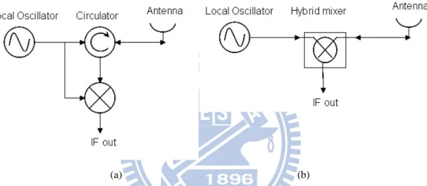
Figure 2.1 (a) A typical single antenna radar transceiver front-end architecture and (b) the architecture using the proposed LO transparent hybrid mixer……….…12 Figure 2.2 Sketch of the new LO transparent hybrid mixer………...13 Figure 2.3 Complete circuit schematic of the LO transparent hybrid mixer…..14 Figure 2.4 Block diagram of (a) conventional quadrature radar with branch-line
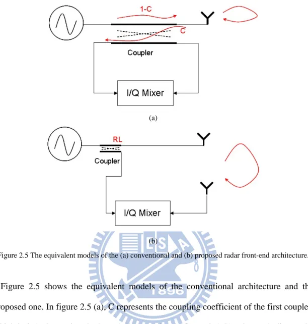
coupler and quadrature mixer, and (b) the proposed radar with LO transmissive quadrature hybrid mixer………..……….15 Figure 2.5 The equivalent models of the (a) conventional and (b) proposed radar front-end architecture………16 Figure 2.6 Schematic of the LO transmissive quadrature hybrid mixer…..…...17 Figure 2.7 The block diagram of the full-duplex bi-directional amplifier……..21
Chapter 3 Design and Measurement of a Doppler Radar using the LO Transmissive Quadrature Hybrid Mixer
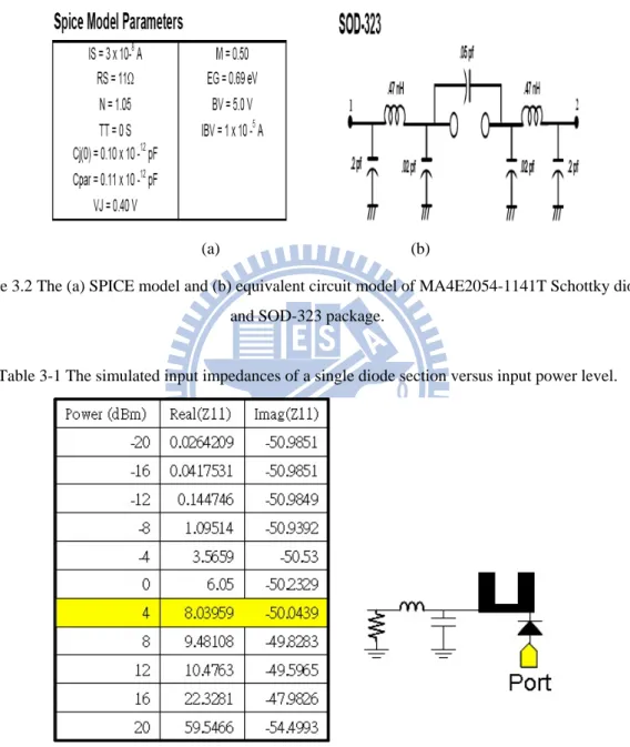
Figure 3.1 Block diagram of the single antenna radar transceiver using the proposed LO transmissive quadrature hybrid mixer……….23 Figure 3.2 The (a) SPICE model and (b) equivalent circuit model of
MA4E2054-1141T Schottky diode and SOD-323 package………..25 Figure 3.3 Smith chart of the simulated input impedances of a single diode
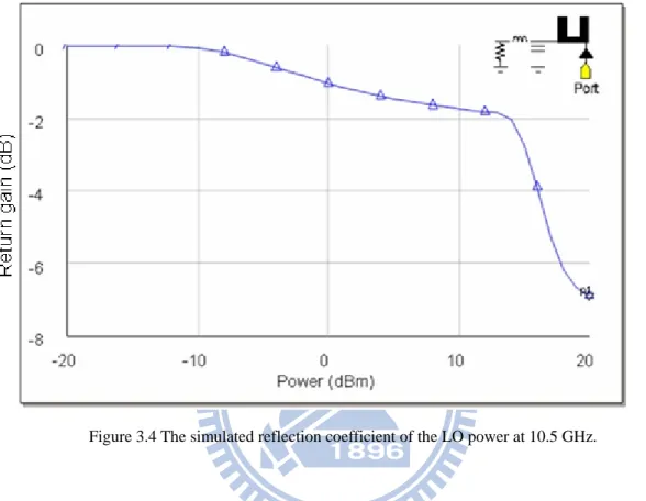
section at 10.5 GHz………...26 Figure 3.4 The simulated reflection coefficient of the LO power at 10.5
GHz………...27 Figure 3.5 The simulated reflection coefficient of LO and RF signals.………..29 Figure 3.6 Photograph of the LO transmissive quadrature hybrid mixer……...29 Figure 3.7 Simulated and measured conversion gain and the insertion loss from
LO to antenna of the proposed quadrature hybrid mixer…….…….30 Figure 3.8 Measured performance of the proposed quadrature hybrid mixer
gain of the quadrature hybrid mixer with LO power 0 dBm……....33 Figure 3.10 Measured insertion loss, conversion loss, and total loss of the LO
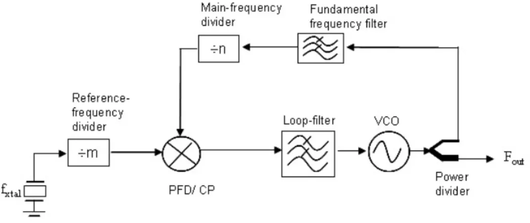
transmissive quadrature hybrid mixer versus bias voltage with different LO power levels……….35 Figure 3.11 Measured largest 2nd harmonic signal strength…………..………37 Figure 3.12 Block diagram of a typical PLL frequency synthesizer…………..37 Figure 3.13 Schematic of the negative-impedance implementation using the
BFG425W……….39 Figure 3.14 Simulation result of the negative-impedance section………..39 Figure 3.15 (a) A sketch of the two-section DGS and (b) the equivalent circuit
model of the two-section DGS………..41 Figure 3.16 The measurement result of the two-section DGS………41 Figure 3.17 Schematic of the resonator design (a) with DGS and (b) without
DGS………..42 Figure 3.18 Simulation results of the resonator with and without DGS……….42 Figure 3.19 Measured output frequency versus the tuning voltage of the
implemented VCO with DGS………..……….43 Figure 3.20 Schematic of the 5.25 GHz frequency synthesizer with two-section
DGS………..44 Figure 3.21 (a) A photograph of the implemented unequal power divider and (b) measurement result………...45 Figure 3.22 (a) A photograph of the implemented 5.25 GHz low-pass filter and
(b) measurement result………..46 Figure 3.23 Photographs the 5.25 GHz PLL frequency synthesizer with
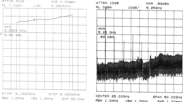
DGS………...46 Figure 3.24 Measured (a) output power and (b) harmonic frequency spectrum of
the 5.25 GHz frequency synthesizer……….…………....47 Figure 3.25 Measured phase noise performance of the implemented 5.25 GHz
frequency synthesizer………48 Figure 3.26 Circuit schematic diagram of the 5.25 GHz active frequency
doubler………..49 Figure 3.27 Simulated (a) output power and (b) harmonic spectrum of the
frequency doubler with input power 4 dBm…...………..50 Figure 3.28 Photograph of 5.25GHz to 10.5GHz frequency doubler………….51 Figure 3.29 Measured (a) output power and (b) harmonic spectrum of the
Figure 3.31 (a) A photograph of the edge-coupled microstrip BPF and (b) the measurement result………...53 Figure 3.32 Complete schematic of the 10.5 GHz Doppler radar transceiver…54 Figure 3.33 Photograph of the integrated 10.5 GHz Doppler radar
transceiver……….55 Figure 3.34 Measured phase noises of the radar transceiver at 10.5GHz when
output power is (a) 0 dBm and (b) 6 dBm………56 Figure 3.35 Measured harmonic spectrums of the radar transceiver when output
power is (a) 0 dBm and (b) 6 dBm………...57 Figure 3.36 Measured output power of the presented radar transceiver with
frequency sweep from 10.36 to 10.76 GHz………..58 Figure 3.37 Simulated conversion losses of the proposed hybrid mixer and a
ring mixer………..…59 Figure 3.38 Photograph of the quadrature mixer using the conventional ring
mixer architecture……….59 Figure 3.39 The environment (a) setup and (b) picture for the radar architecture
evaluation………..60 Figure 3.40 The received power at each IF ports of (a) the LO transmissive
quadrature hybrid mixer and (b) a conventional quadrature
mixer...61 Figure 3.41 Signal processing flow of accumulating the total received
power...62 Figure 3.42 Measured power spectrums of the received I / Q signals with input
power of (a) 0 dBm, (b) 5 dBm, and (c) 10 dBm………...63 Figure 3.43 Accumulated power at all ports versus the input power level…….64 Figure 3.44 Received power of the LO transmissive quadrature hybrid mixer
and conventional one versus LO power level………...64 Figure 3.45 Environment setup to measure the Doppler radar module
performance of acquiring the ground speed………..65 Figure 3.46 The acquired time-domain waveforms of the base-band signal from
the output of the quadrature hybrid mixer for (a) a target with speed of 60 km/hr moving toward the sensor, and (b) a target with speed of -45 km/hr moving away from the sensor………..67 Figure 3.47 The power spectrum densities of the quadrature signal acquired
from the proposed Doppler radar transceiver with (a) an approaching target with speed of 60 km/hr, and (b) a leaving target with speed of
Chapter 4 24 GHz Vehicle Collision Warning Radars
Figure 4.1 Modulation waveform of the FMCW mechanism……….69 Figure 4.2 (a) Schematic and (b) photograph of the 6 GHz VCO………..73 Figure 4.3 Measured (a) output frequency and (b) the phase noise of the 6 GHz
VCO………..74 Figure 4.4 (a) Schematic and (b) photograph of the 6 to 12 GHz frequency
doubler………..75 Figure 4.5 Measured (a) conversion loss and (b) output harmonic powers of the
frequency doubler with input power of 8 dBm……….76 Figure 4.6 (a) Schematic and (b) photograph of the 12 to 24 GHz frequency
doubler………..76 Figure 4.7 Measured conversion loss of the 12 to 24 GHz frequency
doubler………..77 Figure 4.8 (a) Schematic and (b) photograph of the 12 GHz gain block………77 Figure 4.9 Measured (a) frequency response and (b) output power of the 12
GHz gain block……….………78 Figure 4.10 (a) Schematic and (b) photograph of the 24 GHz LNA…………..79 Figure 4.11 Measured gain and noise figure of the 24 GHz LNA………...…...80 Figure 4.12 Schematic of the SHM……….81 Figure 4.13 Measured conversion loss of the SHM………..……..81 Figure 4.14 Blind spot area around a small vehicle and sideway-looking radar
coverage area……….………...82 Figure 4.15 Block diagram of the 24 GHz sideway-looking radar…………...83 Figure 4.16 The architecture of the patch-fed horn antenna………...84 Figure 4.17 Measured antenna directivity of the patch-fed horn antenna……..84 Figure 4.18 Photographs of (a) RF circuit board, (b) base-band circuit board,
and (c) the integrated 24 GHz sideway-looking radar…………..…85 Figure 4.19 DSP result of the radar echo when two targets are located in a
distance of 7 and 10 meters………...86 Figure 4.20 System block diagram of the 24 GHz forward-looking radar…….87 Figure 4.21 Architecture of the 9x8 series-fed antenna array……….…88 Figure 4.22 (a) The antenna directivity and (b) return loss of the 9x8 series-fed
antenna array……….89 Figure 4.23 (a) Backside and (b) front-side photographs of fabricated 24 GHz
Figure 4.26 Tuning voltage (up) and frequency discriminator output (down) of the frequency linearizer (a) before and (b) after
linearization………...92 Figure 4.27 Sampling mechanism for the 2D-FFT function……….……..93 Figure 4.28 DSP flow chart of the 24 GHz forward-looking radar system……95 Figure 4.29 A screen shot of the 2D power spectrum. (A human in 11.5 meters
away moving toward the radar with relative speed 4 km/hr)……....95
Chapter 5 A Compact RF Front-End Configuration for Short-Range Communication
Figure 5.1 Block diagram of the transceiver front-end using the full-duplex bi -directional amplifier………97 Figure 5.2 Schematic of the reflection-type amplifier……….…..98 Figure 5.3 Simulated and measured return gain of the reflection-type
amplifier………99 Figure 5.4 Photograph of the bi-directional amplifier………..100 Figure 5.5 Measured bi-directional gains of the bi-directional amplifier…….100 Figure 5.6 Measured return loss of the fabricated planar Yagi -antenna……..101 Figure 5.7 Simulated radiation pattern of the planar Yagi-antenna……….….102 Figure 5.8 Photograph of the implemented transceiver front-end using the bi
-directional amplifier architecture………..…….102 Figure 5.9 Measured overall conversion gain of the bi-directional transceiver
Chapter 1 Introduction
Table 1-1 A comparison of the existing sensing technologies………4
Chapter 3 Design and Measurement of a Doppler Radar using the LO Transmissive Quadrature Hybrid Mixer
Table 3-1 The simulated input impedances of a single diode section versus input power level………25 Table 3-2 The simulated input impedances of a two-tone signal in a single diode
section………...28 Table 3-3 Measured quadrature hybrid mixer performance versus bias
voltage………...33 Table 3-4 Summary of the optimized bias point and performance of the
proposed quadrature hybrid mixer versus LO power level………...36 Table 3-5 Measured output performance of the implemented 5.25 GHz VCO
with DGS………..43 Table 3-6 Summary of ground speed measurement………66
Chapter 4 24 GHz Vehicle Collision Warning Radars
Chapter 1 Introduction
Microwave technology has attracted many attentions in many fields. These applications can be grouped into radar and communication systems. The microwave radar technology has been applied in many aspects in our life such as speed detection sensors, vehicle collision warning radars, traffic control monitors, health-care equipments, and motion detectors [1]. Among these applications, high performance, compact size, simple structure, and low cost are the most essential to these radars [2]. This dissertation proposes a new LO transparent hybrid mixer, a LO transmissive quadrature mixer, and a radar front-end architecture using the proposed mixer. By using the presented LO transparent mixer architecture, single antenna radar transceiver front-end can be achieved with simple circuit frame. This dissertation also proposes a novel full-duplex bi-directional amplifier, which can reduce the front-end circuit complexity in a short-range communication system. The first section of this chapter describes the motivation of this research and discusses the related radar front-end and the bi-directional amplifier design literatures. The contributions of this study are presented in the following section. Lastly, the outline of this dissertation is provided.
1.1 Motivation
Followed by the development of economy and technology, vehicle nowadays is quite popular. According to the report from the United Nations Environment Programme (UNEP) in 2009 [3], the total quantity of vehicles in 2050 will be three times as many as recent day. Because of the explosive increase of cars, traffic has become one of the most severe problems in the developed countries. The Intelligent-Transportation System (ITS) is considered as one of the most efficient
solution to the traffic problem [4]-[6]. By sharing the information and managing it, the ITS tends to minimize the traffic problem by tuning the existing transportation network more efficient. The ITS is composed of 5 major parts, (a) the Advanced Traveler Information System (ATIS), (b) Advanced Traffic Management System (ATMS), (c) Advanced Vehicle Control and Safety System (AVCSS), (d) Commercial Vehicle Organization (CVO), and (e) Advanced Public Transportation System (APTC). Among these systems, the (a), (b), (d), and (e) parts are focused on the traffic management and construction of infrastructures. The (c) part is an on board unit.
The AVCSS is also considered as the core to achieve smart transportation system. The AVCSS provides a safer and more comfortable driving experience to the drivers. Because the system is to be installed on a car, the potential market can be expected. The vehicle collision warning radar plays an important role in the AVCSS [7]-[8].
The vehicle collision warning sensor can be realized using sonar, infrared rays, vision, and microwave radar technologies. Because of the superior characteristics of working in all kinds of weather and environmental condition, the microwave radar is chosen by most of the auto-makers. The radar technology was developed since World-War II, as the detector of enemy airplanes. Now the radar has been integrated on a small vehicle, as a driver assistant unit [9]. As a complement of human sense, the automotive radar has been found in many auto-industry applications such as Adaptive Cruise Control (ACC), Blind-Spot Detecting System (BLDS), and so on. The radar can also be built on the road-side, to measure the quantity and average speed of vehicle flow [10]. The information of vehicle flow is quite helpful to the traffic control system.
Figure 1.1 A sketch of the automotive radar applications within a car.
In general, there should be a forward-looking radar, two sideward-looking radar, and a backward-looking radar in a single vehicle to cover all the surrounding area, as illustrated in figure 1.1. Each radar takes care a specified region and provides different warning to the driver [11]. For example, the forward-looking radar tracks the distance and relative speed of vehicles in front of the radar vehicle itself, then warns if necessary [12]-[13]. The forward-looking radar gives the driver an extra reaction time, which may help to reduce the car accident rate. The sideward-looking radar detects the blind-spot area of a vehicle. This radar can be a driver assistant system to provide a visual and sound warning. The backward-radar senses the rear region of a vehicle and searches for the potential danger. The backward-radar is significantly useful in large vehicles, which the drivers may not be able to look the back region through a mirror [14]-[15].
Several available sensing technologies can provide solutions to detect objects in the nearby region, such as sonar (ultrasonic wave), light (visible light, laser, infrared rays), and microwave technologies. Table 1-1 [16] gives a comparison of all existing sensing technologies. The sonar fails under high air flow speed environment, thus, this technology is impossible to be used when the vehicle running in high speed. The
infrared rays, laser, and video sensing technologies fail in a dirty or moist environment. Only the microwave radar technology survives in all kinds of weather condition.
Table 1-1 A comparison of the existing sensing technologies.
Since 1972, the moat large auto-makers in this world have developed their own automotive radar systems. In 1990s, many applications have been proposed by using the radar technology. To be installed on a small vehicle and accepted by the mass population, developing a compact and low cost radar system becomes the major trend.
The microwave radars are composed of the transmitting / receiving antenna(s), Radio-Frequency (RF) transceiver, and a Digital Signal Processor (DSP). Various modulation mechanisms in both pulsed and Continuous-Wave (CW) type have been developed to obtain the target information [17]. Among these mechanisms the Linear Frequency Modulated Continuous-Wave Modulation (LFMCW) is commonly used in automotive radar applications. This modulation provides target distance and speed information in single acquisition with relative good resolution and simple front-end circuit complexity [18].
Personal wireless communication brings a significant convenience to our life. To be used on a portable device, the compact and relative low cost transceiver architecture
recent years, numerous new transceiver architectures have been proposed to simplify the front-end circuit configuration and to reduce the system cost. The transceiver with single antenna is considered to have the minimum size. In the typical single antenna architecture, signal switches or diplexers are used to separate the transmitting and receiving paths. These components increase the circuit complexity and thus reflect on the price. The bi-directional amplifier concept is proposed to eliminate the usage of signal split components [19].
1.2 Literature Survey
Among the radar technologies, the CW radars have relatively simple circuit structure, allowing the compact size and low-cost solutions [20]. This kind of radar has been found in many applications within the automotive field such as speed sensor, collision warning radar, and traffic control systems [21]. Among these systems, a single local oscillator (LO) is used to generate transmitting power and drive the receiver at the same time, as shown in figure 1.2.
Figure 1.2 Block diagram of the continuous wave radar transceiver.
Because there is only one signal source, the LO power usage efficiency is used to state how efficient the radar front-end use the LO power in both transmitting and receiving ways. For short range applications, the CW radars with low-power LO have
the optimum size and cost. In the associated applications such as health-care sensor and speed detector, a high LO power usage efficiency is crucial to improve the sensing quality. The higher LO power usage efficiency implies higher signal strength can be acquired from the sensor with the same LO power inject into the radar. The systems with two antennas are likely to have best local power usage efficiency regardless the transmission loss in the power distribution network [22]-[23]. However, the system size is twice larger than the system with single antenna. The radar with single antenna is typically implemented with a circulator or a coupler following the antenna. The circulator components usually cost extremely high price, while in the coupler architecture half of the receiving power is dissipated at the LO port, in addition, half of the transmission power is taken to drive the mixer. In this thesis, a new LO transparent type hybrid mixer is proposed in order to improve the power usage efficiency of the local oscillator. The proposed hybrid mixer is placed in series between the signal source and antenna. It has the characteristic to pass the LO power through and down convert the radar signal. The proposed hybrid mixer has been proven that fewer than half power is required to drive the mixer and no power is lost in the receiving path.
The quadrature radars, as shown in figure 1.3, can detect the speed and direction of a target. This kind of radar can also be used to measure the displacement of objects in a static environment [24]-[25]. Extremely small displacements such as human vital signals are detected very well with quadrature mixing technology [26]-[27], because this kind of radar extracts Doppler signal with much higher signal-to-noise ratio [28].
Figure 1.3 A classic quadrature radar architecture.
The typical single antenna quadrature radar architecture applied a coupler to isolate the transmitter and receiver paths. C. Y. Kim [29]-[30] proposed a balanced coupler network and a circularly polarized radar architecture to improve the transmitter-to-receiver leakage. However, these approaches suffer from low power usage efficiency that the reflected LO powers from the mixers are terminated at a resistor and half of the receiving power is dissipated in the LO port. In the following of this dissertation, a LO transmissive quadrature hybrid mixer is proposed. The new quadrature hybrid mixer can perform the same function as the quadrature mixer and improve the local power usage efficiency as well.
In the short-range communication systems, the design of transceiver is not focused on increasing the communication distance but on the convenience in the near proximity area of the users. Thus, the circuit performance can be somewhat sacrificed in order to obtain a compact and low-cost circuit configuration. The typical wireless front-end circuit of the transceivers contains two individual signal paths, one for transmitting and the other for receiving. The use of two individual T/R paths has the advantages of achieving optimum designs for each path and result in an improved communication
components, more complicated circuit layout, and larger circuit area. T. Tsukii [31] and J. W. Archer [32] presented single-path transceiver architectures using a switched bi-directional amplifier. The transmitting signal and the receiving signal share the common RF circuits, and thus simplify the circuitry complexity. However, these architectures can only be used in a half-duplex system. In this dissertation, a compact RF front-end configuration using a novel full-duplex bi-directional amplifier is presented. The proposed bi-directional amplifier is composed of a quadrature hybrid and reflection type amplifiers. Without using the signal switch, this configuration requires only one path for the transmitting / receiving signals and can be used in both half- and full-duplex systems.
1.3 Contributions
In this dissertation, a new LO transparent hybrid mixer, a unique LO transmissive quadrature hybrid mixer, and novel full-duplex bi-directional amplifier architectures are presented. A radar front-end architecture using the proposed hybrid mixer is proposed. The proposed radar architecture can reduce the transmission power loss and has no received power wasted in the signal split network in theory. Thus, an optimized LO power usage efficiency is achieved. A 10.5 GHz Doppler radar system is implemented using the proposed LO transmissive quadrature hybrid mixer architecture. A local oscillator designed with the defected-ground-structure, which possesses a low phase noise, is applied as the local oscillator to the radar. A frequency synthesizer is implemented to provide a stable signal source in all kinds of operation environment. A complete radar transceiver with the proposed quadrature hybrid mixer is implemented and tested.
developed for the sideway-looking and forward-looking applications, respectively. The RF front-ends, antennas, and base-band signal processor within the 24 GHz radars are built up. The LFMCW mechanism is applied in these radar systems, also a modulation linearizer is adopted to improve the modulation linearity. A 2D-FFT signal processing algorithm is presented for simultaneously measuring the object relative speed and distance.
A new transceiver front-end architecture using the proposed full-duplex bi-directional amplifier for wireless communication is presented. Without using the signal switch or diplexer, the transceiver fulfills full / half duplex functionalities in single path architecture. The transceiver complexity is minimized when using the bi-directional amplifier.
1.4 Outline of the Dissertation
This dissertation is organized as follows: The chapter-2 proposes the new quadrature hybrid composed circuits. A new LO transparent hybrid mixer is proposed for the radar applications, which offers a solution to reduce the front-end circuit complexity and cost. The operation principle of the proposed hybrid mixer is illustrated. A unique LO transmissive quadrature hybrid mixer is presented, which provides two orthogonal base-band outputs. These orthogonal outputs make the radar receiver able to identify direction of displacement. The basis of the proposed quadrature hybrid mixer is illustrated. Then, a novel full-duplex bi-directional amplifier is also presented, which is proposed to simplify the RF front-end in a wireless communication system. The bi-directional architecture and operation principle are described in this chapter.
Chapter 3 presents a 10.5 GHz quadrature radar using the LO transmissive quadrature hybrid mixer. The implementation of 10.5 GHz radar transceiver is
illustrated, which includes a proposed quadrature hybrid mixer, a 5.25 GHz defected-ground structure VCO, a Phase-Lock Loop (PLL) frequency synthesizer, and an active frequency doubler. The output performance of the implemented transceiver is presented. Then, a performance comparison of the radar front-end architecture between the conventional one and the proposed one using the quadrature hybrid mixer is presented. A test environment is built to simulate a continuously moving object with constant relative speed. At the end of this chapter, the radar transceiver is established as a road-side unit to measure the speed of vehicles passing by.
Chapter 4 presents two complete 24 GHz collision warning radar systems. The 24GHz radars are developed with one for the side-way looking and the other one for the forward-looking applications. A 6 GHz VCO is designed as the signal source, then, two active type frequency doublers multiply the 6 GHz signal to the 24 GHz required signal. A sub-harmonic mixer is adopted in this study to down convert the radar signal to base-band directly. A modulation linearizer mechanism is proposed to provide excellent frequency modulation linearity. A 2D-FFT signal processing algorithm is presented, which shows a capability to acquire the relative speed and distance information of moving objects, simultaneously.
Chapter 5 proposes a new transceiver RF front-end using the full-duplex bi-directional amplifier. The design of bi-directional amplifier is illustrated. A RF front-end composed of a bi-directional amplifier, a ring mixer, and a printed Yagi-antenna is implemented. The proposed architecture shows a capability to transmit / receive signals using single path.
Chapter 2
New Quadrature Hybrid Composed
Circuits
In this chapter, a new LO transparent hybrid mixer, a LO transmissive quadrature hybrid mixer, and a novel full-duplex bi-directional amplifier are proposed. These new mixers and amplifier are configured using the quadrature hybrid architecture. Different from the conventional mixers, the proposed hybrid mixers are designed to pass the local oscillator power to the antenna port, and also able to down-convert the received signal from antenna. Having this unique characteristic, the proposed hybrid mixer architecture is suitable to be used in the radar front-end. Using the LO transparent hybrid mixer, single path transmitting / receiving can be accomplished with simple circuit complexity. A LO transmissive quadrature hybrid mixer composed of the new hybrid mixers is then presented. The quadrature hybrid mixer not only has the same performance as the hybrid one but also output both the I / Q IF signals simultaneously. These I / Q signals are useful to distinguish the sign of frequency shift in the Doppler radar applications, which helps to recognize the sign of relative speed. In the end of this chapter, a full-duplex bi-directional amplifier is presented. With the unique characteristic of enhancing the signals in both transmitting and receiving path, the bi-directional amplifier is proposed to simplify the RF front-end complexity when used in a short-distance communication system.
2.1 New LO transparent hybrid mixer
Most radar systems use single signal source as detecting signal and local oscillating signal to the receiver. Among these radar systems the single antenna architecture is considered to have the smallest size and simplest circuit complexity. As
illustrated in figure 2.1 (a), a circulator component is commonly used to isolate the input and output signals in the conventional radar system. However, the circulator device costs extremely high price. In this thesis, a LO transparent hybrid mixer architecture is proposed for the radar applications. As shown in figure 2.1 (b), the proposed hybrid mixer is connected in series between the local source and antenna, which has the capability to bypass the local power to the antenna and down convert the received radar signal to base-band as well.
(a) (b)
Figure 2.1 (a) A typical single antenna radar transceiver front-end architecture and (b) the architecture using the proposed LO transparent hybrid mixer.
Owning to the reason that the radar system uses the same signal source as the transmitting signal and down converter driving signal, there is no LO to RF isolation problem in the radar systems. Instead, the idea of LO transparent hybrid mixer tends to maximize the LO to RF transmission. As illustrated in figure 2.2, the new LO transparent hybrid mixer is composed of a 90° half-power coupler, two mixer diodes, and Low-Pass Filters (LPFs).
Figure 2.2 The sketch of the new LO transparent hybrid mixer.
Let the RF and LO signals expressed as:
( )
(
)
( )
(
)
RF R LO Tcos
cos
RF RF LO LOV
t
A
t
V
t
A
t
ω
θ
ω
θ
=
+
=
+
(2-1)where ARF and ALO represent the received and local oscillator amplitude respectively.
R
ω and ωT indicate the frequencies of the received and transmitted signal. After
passing through the 90° coupler, the signals at the mixer diodes can be expressed as:
( )
(
)
( )
(
)
LO RF 1 R T LO RF 2 R Tcos
cos
2
2
2
cos
cos
2
2
2
D RF LO D Rf LOA
A
V
t
t
t
A
A
V
t
t
t
π
ω
θ
ω
θ
π
ω
θ
ω
θ
⎛
⎞
=
+
+
⎜
+
+
⎟
⎝
⎠
⎛
⎞
=
⎜
+
+
⎟
+
+
⎝
⎠
(2-2)After mixing the contents within VD1(t) and VD2(t), the fundamental term can be filtered
out by the LPF and thus expressed as:
( )
(
)
( )
(
)
1 R T 2 R Tcos
2
2
cos
2
2
RF IF c d RF IF c dA
V
t
t
A
V
t
t
π
α
ω
ω
θ
π
α
ω
ω
θ
⎛
⎞
=
⎜
−
+
−
⎟
⎝
⎠
⎛
⎞
=
⎜
−
+
+
⎟
⎝
⎠
(2-3)strength, diode characteristic, and LPF efficiency.
Figure 2.3 Complete circuit schematic of the LO transparent hybrid mixer.
Figure 2.3 gives a complete circuit schematic of the LO transparent hybrid mixer. A branch-line coupler is adopted as the 90° half-power coupler. Two mixer diodes are connected in parallel. A quarter-wavelength open stub is connected at the end of mixer
diode. The λ4 open stubs provide both the RF and LO signal the small signal ground.
An inductor and capacitor composed LPF is connected to the IF output. The resistors connected at each end of the LPF provide discharge paths for the DC components generated by mixer diodes. A differential amplifier which converts the differential output to single-ended with required first stage gain, is connected to the IF outputs,
2.2 The LO transmissive quadrature hybrid mixer
Figure 2.4 (a) and (b) illustrate the block diagrams of the quadrature radar transceivers with conventional mixers and with the proposed LO transmissive quadrature hybrid mixer, respectively. The conventional radar consists of an antenna, an LO source, two branch-line couplers, a two-way power divider, and two mixers along with two LPFs. In
receiving signals, while the other one is to generate two LO signals with 90° phase difference for quadrature mixing. Half of the output power from the signal source is transferred to the antenna through the first quadrature coupler. During the receiving process, the received signal is coupled to the mixer by the first quadrature coupler and down converted to the base-band by the mixers. The unwanted higher-order harmonic signals are rejected by the LPFs.
Antenna Quadrature coupler 50 Ω termination Wilkinson power divider Local oscillator Mixer Mixer LPF LPF Q I 1 2 Antenna Quadrature coupler 50 Ω termination Wilkinson power divider Local oscillator Mixer Mixer LPF LPF Q I Antenna Quadrature coupler 50 Ω termination Wilkinson power divider Local oscillator Mixer Mixer LPF LPF Q I 1 2 (a) (b)
Figure 2.4 Block diagram of (a) conventional quadrature radar with branch-line coupler and quadrature mixer, and (b) the proposed radar with LO transmissive quadrature hybrid mixer.
(a)
(b)
Figure 2.5 The equivalent models of the (a) conventional and (b) proposed radar front-end architecture.
Figure 2.5 shows the equivalent models of the conventional architecture and the proposed one. In figure 2.5 (a), C represents the coupling coefficient of the first coupler, which is 0.5 when using the branch-line coupler. In figure 2.5 (b), The RL indicates the power loss due to a certain of the LO power is taken to pump the mixer diodes. From the ideal model, the conventional architecture shown in figure 2.4 (a) has significant power loss. In spite of the transmission loss contributed by the transmission lines and path loss from antenna to object, there are always 6 dB power loss contributed by the quadrature coupler in theory. There is 3 dB power loss in the transmitting path that half of the transmitting power is transferred to drive the mixers. Another 3 dB loss that half of the received power is terminated at the LO port in the receiving path. The proposed architecture shown in figure 2.4 (b) is used to solve problem. During transmitting process, the LO power is equally divided by the first quadrature coupler and put into the
LO transparent hybrid mixers. The hybrid mixer takes the necessary energy it needs to drive the mixing diodes only, and then pass the remnant power through. Eventually, the remained power from the two hybrid mixers is combined at the antenna port of the second quadrature coupler. When receiving, the second quadrature coupler divides the received power equally with 90° phase difference and put into the mixers. In theory, this architecture has 6 dB enhancement of overall performance from the equivalent model. In practice, a certain of LO power injected into the hybrid mixer is taken to drive the mixer diodes. The power taken by mixer diodes is typically lower than half of the total LO power. Therefore, the overall LO power is efficiently used in this architecture. Note that there are two 45° delay lines placed individually in the upper and lower paths to produce the required phase difference of I / Q IF signals.
Figure 2.6 Schematic of the LO transmissive quadrature hybrid mixer.
Figure 2.6 illustrates the complete schematic of the proposed LO transmissive quadrature hybrid mixer, which consists of two hybrid mixers and two attached 90°
Schottky diodes, and followed be two LPFs. Let the signal from the LO be given by:
( )
LO LO
cos
TV
=
A
ω
t
(2-4)where ALO is the amplitude of the LO signal and ωT the LO frequency (which is also the
frequency of the transmitting signal). After passing through the first quadrature coupler
and the 45° delay line, the signal, VI, entering the upper hybrid mixer (mixer-I) can be
expressed as: I LO T
5
cos
4
2
A
V
=
⎛
⎜
ω
t
−
π
⎞
⎟
⎝
⎠
(2-5)This signal is then divided into two parts by the branch line coupler in the hybrid mixer
and delivered to the two Schottky diodes D1 and D2, where these signals have the forms
of: LO TD1
cos
T2
4
A
V
=
⎛
⎜
ω +
t
π
⎞
⎟
⎝
⎠
(2-6) LO TD2cos
T2
4
A
V
=
⎛
⎜
ω
t
−
π
⎞
⎟
⎝
⎠
(2-7)The signal power here is used to drive for the mixer operation, after that, most power is
reflected from the diodes with a large reflection coefficient αD, and eventually, the
reflected powers combine at the RF port of the hybrid mixer-I as:
I LO T D T
3
cos
4
2
A
V
=
α
⎛
⎜
ω
t
−
π
⎞
⎟
⎝
⎠
(2-8)In the mean time, the LO signal also enters the lower hybrid mixer (mixer-II),
( )
II LO T Dcos
T2
A
V
=
α
ω
t
(2-9)This output signal from mixer-II passes through the 45° delay line and then enters the second quadrature coupler. The LO signal passing through mixer-II combines with the signal from mixer-I at the antenna port of the second branch-line coupler. The combined transmitting signal at the antenna port is obtained as:
T LO D T
5
cos
4
V
=
A
α
⎛
⎜
ω
t
−
π
⎞
⎟
⎝
⎠
(2-10)It is seen that only the reflection loss (
1/
α
D) at the Schottky diodes contributes to theinsertion loss of the transmitting signal from LO to antenna.
In the receiving path, the signal received by the antenna can be given by:
(
)
R R
cos
RV
=
A
ω
t
(2-11)where AR and
ω
R are the amplitude and frequency of the signal received. After passingthrough the second branch-line coupler and entering hybrid mixer-I, the received signals
at diodes D1 and D2 are given by:
R RD1 R
3
cos
2
2
A
V
=
⎛
⎜
ω
t
−
π
⎞
⎟
⎝
⎠
(2-12)(
)
R RD2cos
R2
A
V
=
ω
t
−
π
(2-13)These signals are mixed with the LO signals (2-6) and (2-7), respectively, leading to the output of fundamental harmonics obtained as:
(
)
R IF1 Lcos
T R2
4
A
V
=
C
⎛
⎜
ω
−
ω
t
−
π
⎞
⎟
⎝
⎠
(2-14)(
)
R IF2 L T R IF13
cos
2
4
A
V
C
t
V
π
ω
ω
⎛
⎞
=
⎜
−
+
⎟
⎝
⎠
= −
(2-15)where CL is the conversion coefficient of the mixer diode, 1/ CL is also expressed as the
mixer conversion loss. The outputs at these IF port within a single hybrid mixer section
are out of phase, therefore, a low-noise differential amplifier with gain of Gdiff is used
here to convert the differential signal into single-ended. The differential amplifier can also help to reject the common-mode noise which helps to improve the receiver sensitivity [33]. After this amplifier, the received IF signal at the in-phase port (I port) has the following form:
(
)
I IF R diff Lcos
T R4
V
=
A G
C
⎛
⎜
ω
−
ω
t
−
π
⎞
⎟
⎝
⎠
(2-16)Similarly, the IF signal at the quadrature-phase port (Q port) can be derived as
(
)
Q IF R diff Lcos
T R4
V
=
A G
C
⎛
⎜
ω
−
ω
t
+
π
⎞
⎟
⎝
⎠
(2-17)Apparently, the IF outputs at both I and Q ports of the mixer are equal amplitude and 90° difference in phase.
2.3 The full-duplex bi-directional amplifier
Figure 2.7 The block diagram of the full-duplex bi-directional amplifier.
Figure 2.7 shows the proposed configuration of the full-duplex bi-directional amplifier, which contains two reflection-type amplifiers and a quadrature hybrid. The amplifiers are connected to the output ports 2 and 3 of the hybrid, respectively. The input and isolating ports of the hybrid serve as the input / output ports of the bi-directional amplifier.
The scattered wave coming out from the quadrature hybrid is V− = ⎣⎡V1−,V2−,V3−,V4−⎤⎦T, where the scattering matrix of the quadrature hybrid is [34]:
[ ]
0
1
0
0
0
1
1
1
0
0
2
0
1
0
j
j
S
j
j
⎡
⎤
⎢
⎥
− ⎢
⎥
=
⎢
⎥
⎢
⎥
⎣
⎦
(2-18)Let only the port-1 have wave incident and port-4 be terminated. The scattering wave at port-2 and 3 are expressed as:
2 1 3 1
1
,
2
2
j
V
−=
−
V
+V
−=
−
V
+ (2-19)Noting that the reflection-type amplifier with gain G at port-2 and -3 (V2+ =GV2−,
3 3
V+ =GV−), the outputs at port-1 and 4 are then obtained:
1
0,
4 1V
−=
V
−=
jGV
+ (2-20)It is seen that no power is reflected back to the input port and that the transmission gain
4
/
1V
−V
+ is the same as the gain G of the reflection-type amplifiers. Owing to thesymmetric architecture, the same result can also be derived when wave is excited from port-4 to port-1.
In practice, the reflection-type amplifiers will have small performance deviation, which maybe cause by the mismatch of active components used in the reflection-type amplifiers.
The slight gain deviation
Δ
G
causes the reflection coefficient and transmission gainbecomes: 1 1
2
V
G
V
− +Δ
=
(2-21) and 4 11
2
V
G
G
V
G
− +Δ
⎛
⎞
=
⎜
+
⎟
⎝
⎠
(2-22)The same results can be obtained when wave is coming from the port-4. It is seen that the gain deviation mainly contributes to the reflection coefficient, only little change in the transmission gain.
Chapter 3
Design and Measurement of a Doppler
Radar using the LO Transmissive
Quadrature Hybrid Mixer
In this chapter, a 10.5 GHz Doppler radar transceiver using the LO transmissive quadrature hybrid mixer is presented. The new transceiver architecture is proposed with higher LO power usage efficiency and simpler circuit complexity. The operation principle of the new LO transmissive quadrature hybrid mixer was illustrated in chapter-2. The design of the proposed quadrature hybrid mixer and the other components which compose a complete radar transceiver are illustrated. The performance of the integrated radar transceiver is shown. In the following, another single antenna radar transceiver using the conventional quadrature mixer is fabricated for comparison. An experiment shows the received power is improved in new LO transmissive quadrature hybrid mixer architecture. The implemented radar is also tested on the road side to detect the vehicle flow and their relative speed.
3.1 Development of the 10.5 GHz quadrature radar transceiver
Figure 3.1 Block diagram of the single antenna radar transceiver using proposed LO transmissive quadrature hybrid mixer.
Figure 3.1 illustrates the building block of the proposed radar transceiver front-end using the LO transmissive quadrature hybrid mixer. The transceiver is composed of a 5.25 GHz frequency synthesizer, a frequency doubler, a 10.5 GHz Band-Pass Filter, along with a LO transmissive quadrature hybrid mixer. A stable signal source is vital for the radar application. In this study, the frequency synthesizer architecture is adopted to mend the frequency deviation due to temperature difference or component performance decay. A Defected-Ground-Structure (DGS) is used in the VCO design to provide better phase noise performance. An active frequency doubler is designed to supply the required 10.5 GHz signal from doubling the 5.25 GHz input signal. Instead of using the passive design, the active frequency doubler is chosen for two reasons. First of all, to minimize the component cost, the frequency doubler itself provides sufficient output power for short-range applications, thus the output amplifier not required. Furthermore, the output power can be adjusted on demand by changing the bias voltage to the frequency doubler. A 10.5 GHz BPF is connected to the output of frequency doubler. The 10.5 GHz BPF is used to filter out the unwanted harmonic signals produced by the frequency doubler. The BPF helps to minimize the harmonic signal emission, and also improves the conversion efficiency of frequency doubler. The LO transmissive quadrature hybrid mixer is connected between the BPF and antenna. The mixer performs the function to down-convert the received radar signal and delivers the local signal power to the antenna as well.
3.1.1 The LO transmissive quadrature hybrid mixer
A 10.5 GHz quadrature hybrid mixer is developed at 10.5 GHz, which is composed of branch-line couplers, delay lines, and LO transparent hybrid mixer. The couplers and delay lines are designed using a 2.5-D EM simulator IE3D [35]. The developed
constant 3.38 and thickness 20-mil. The M/A-COM MA4E2054 Schottky diode is selected as the mixer diode in this study. The simulation of large signal is performed using the Ansoft Microwave Office [36]. Figure 3.2 gives SPICE model of the MA4E2054 Schottky diode and equivalent circuit model of the SOD-323 package.
(a) (b)
Figure 3.2 The (a) SPICE model and (b) equivalent circuit model of MA4E2054-1141T Schottky diode and SOD-323 package.
Table 3-1 The simulated input impedances of a single diode section versus input power level.
Table 3-1 gives the simulation result of the diode input impedance versus the input signal strength. In this simulation, a 10.5 GHz single-tone large signal is excited directly into the anode pin of the Schottky diode, where the cathode pin of the diode is connected
to the RF signal. The residual LC components are used to filter out the other harmonic signals to the IF output, which shows no affection to the input impedance. From this result, the input impedance at the excitation level of 4 dBm is 8–j50 ohm. The imaginary part of the input impedance versus input power level does not change observably, however, the real part varies a lot. Figure 3.3 shows the Smith chart of simulated input impedance versus input power level at 10.5 GHz. From this result, the diode acts like a capacitor in low power condition.
Figure 3.3 Smith chart of the simulated input impedances of a single diode section at 10.5 GHz.
Figure 3.4 illustrates how the mixer diode consume the LO power in terms of reflection coefficient. From this result, all the LO power are reflected when power level lower than -10 dBm, mixing signal fails at this condition because the voltage swing does not bigger than the diode barrier voltage. As the power increase, the reflection ratio reduces. When the input power level exceeds 12 dBm, the reflection coefficient drops rapidly, the lost power has been converted into higher order harmonic signals. This is a
From this result, the input power range from 0 to 10 dBm is considered suitable for the mixer design for acceptable reflection coefficient and sufficient LO power do drive the mixer diodes.
Figure 3.4 The simulated reflection coefficient of the LO power at 10.5 GHz.
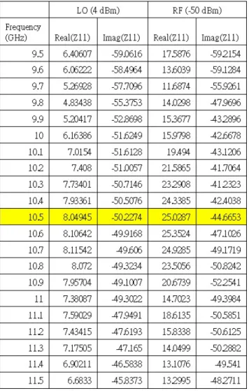
In the hybrid mixer, the RF and LO signals are excited together to the anode pin of mixer diode. The RF signal is considered as a small signal, while the LO is large signal. A two-tone simulation is performed to the mixer diode section to estimate how the RF and LO signals affect each other. Table 3-2 gives simulation result of the two-tone simulation, where the LO signal is excited with a level of 4 dBm and the RF power level of -50 dBm. The input impedance of both LO and RF signal are obtained independently. There is no equipment can measure the two-tone input impedance because the frequency of these two signal are too close, only the simulation can observe the input impedances independently. Compare to the result shown in table 3-1, the input impedance of the LO signal does not change a lot when the RF signal excited. However, the result shows a significant change
signal is 25 - j44.7 ohm, which means most of the RF signal is absorbed by the mixer diode.
Table 3-2 The simulated input impedances of a two-tone signal in a single diode section.
Figure 3.5 shows another simulated reflection coefficients of both LO and RF signals in the mixer diode section. The LO and RF are excited at a level of 10 and -50 dBm, respectively, with a relative frequency difference of 1 MHz. From this result, the return loss of the LO signal is lower than 2 dB around the designed frequency range. Only small percentage of RF signal is reflected by the diode.
Figure 3.5 The simulated reflection coefficient of LO and RF signals.
Figure 3.6 Photograph of the LO transmissive quadrature hybrid mixer.
Figure 3.6 shows a photograph of the implemented LO transmissive quadrature hybrid mixer. Four branch-lines along with four Schottky diodes compose the quadrature hybrid mixer. An external voltage bias network is added, which gives a feasibility to optimize the performance according to different LO power level. The additional bias is
necessary because the change in the transmitting signal power affects the conversion efficiency significantly.
Figure 3.7 Simulated and measured conversion gain of the hybrid mixer and the insertion loss from LO to antenna of the proposed quadrature hybrid mixer.
Figure 3.7 illustrates the measured frequency response of the implemented quadrature hybrid mixer without bias voltage. In this measurement, the insertion loss (includes the
reflection loss 1/
α
D from diode and the overall circuit losses) from LO to antenna, andthe conversion loss (1/ CL) of the quadrature hybrid mixer are shown. This experiment is
executed with an LO power at 10 dBm. Considering that the non-linear characteristic should generate a lot of harmonic signals, these results were measured by a spectrum analyzer. Around the operating point at 10.5 GHz, the mixer shows a conversion loss of 15.5 dB from RF to the I-channel, the insertion loss of 3.1 dB from the signal source to the antenna, and return loss better than 15 dB which covers the range from 9.8 to 11.2 GHz. According to this result, the proposed mixer takes approximate half of the
port. The difference between the simulated and measured ones are caused by the variation of each diode, this unbalance characteristic will slightly deteriorate the mixer conversion and insertion performance. The measured result also shows most of the LO power is reflected by the diode. It shows a good agreement with previous simulation result at single diode stage.
Figure 3.8 Measured performance of the proposed quadrature hybrid mixer without bias versus LO power level.
In the applications like automotive radars, biological sensors, the radars need to be operated under low LO power condition. The performance versus different LO power level is considered. The result illustrated in figure 3.8 gives the insertion loss, conversion loss, and the total loss, versus the LO power level. No bias voltage is applied to the mixer in this measurement. It is observed that, the conversion loss for LO power lower than 0 dBm is extremely high. As the power increases, the conversion loss becomes better, and finally saturates at 15 dB when the LO power is higher than 10 dBm. While only slight insertion loss regression when the LO power increases. In the
single antenna radar architecture, the LO signal leakage to the RF port is used as the interrogating signal of the radar. Therefore, a parameter called the total loss, which is defined as the summation of the conversion loss and insertion loss, is recommended. The total loss shows how many loss contributed by the transceiver itself in both transmitting and receiving path, which provides a better way to estimate the how efficient the LO power is been used in a low power radar system. The total loss in the proposed architecture saturates to 18.2 dB when LO comes more than 10 dBm. An external bias voltage is added in this mixer to enhance conversion efficiency during low LO power level condition. Adding bias voltage to the mixer diode is helpful to lower the barrier-voltage, thus it helps to improve the performance in low power condition [37]. The four diodes within the quadrature hybrid mixer are placed in parallel, therefore these diodes can be biased using a single bias network.
Figure 3.9 gives a simulated transmission and conversion gain of the LO transmissive quadrature hybrid mixer performance with additional bias voltage applied when the LO power is 0 dBm.
(b)
Figure 3.9 Simulation results of the (a) transmission gain and (b) conversion gain of the quadrature hybrid mixer with LO power 0 dBm.
Table 3-3 Measured quadrature hybrid mixer performance versus bias voltage.
0 0.2 0.4 0.6 0.8 1 1.2 1.4 1.6 1.8 2 Insertion Loss 2.15 2.83 3.7 3.12 2.6 2.28 2.1 1.93 1.83 1.76 1.77 Conversion Loss 54.5 21 17.67 18.5 22.17 26.83 31.17 34.83 38.33 40.83 43.67 Total Loss 56.65 23.83 21.37 21.62 24.77 29.11 33.27 36.76 40.16 42.59 45.44 Insertion Loss 2.18 2.93 3.67 3.26 2.66 2.31 2.12 1.94 1.83 1.76 1.76 Conversion Loss 44 20 17.17 17.33 19.33 23.5 27.83 31.83 35.17 38.17 40.83 Total Loss 46.18 22.93 20.84 20.59 21.99 25.81 29.95 33.77 37 39.93 42.59 Insertion Loss 2.25 3.03 3.64 3.37 2.78 2.37 2.16 2.09 1.85 1.79 1.82 Conversion Loss 32.33 19.17 17 16.83 17.5 20 23.83 28 31.83 34.83 37.67 Total Loss 34.58 22.2 20.64 20.2 20.28 22.37 25.99 30.09 33.68 36.62 39.49 Insertion Loss 2.39 3.14 3.61 3.51 2.96 2.48 2.23 2.12 1.89 1.81 1.84 Conversion Loss 24.5 18.67 17 16.83 16.5 17.5 19.67 23.33 27.5 31 34.67 Total Loss 26.89 21.81 20.61 20.34 19.46 19.98 21.9 25.45 29.39 32.81 36.51 Insertion Loss 2.58 3.23 3.59 3.59 3.17 2.65 2.35 2.18 1.93 1.83 1.82 Conversion Loss 21.17 18.17 17.17 16.83 16.33 16.33 17.17 18.83 22 25.67 29.5 Total Loss 23.75 21.4 20.76 20.42 19.5 18.98 19.52 21.01 23.93 27.5 31.32 Insertion Loss 2.8 3.29 3.56 3.63 3.36 2.88 2.55 2.29 2.05 1.9 1.87 Conversion Loss 19.67 18 17 16.83 16.33 16.17 16.5 16.67 17.83 19.83 23 Total Loss 22.47 21.29 20.56 20.46 19.69 19.05 19.05 18.96 19.88 21.73 24.87 Insertion Loss 2.97 3.34 3.55 3.63 3.54 3.1 2.77 2.5 2.23 2.05 2 Conversion Loss 19 17.83 17 16.83 16.5 16.17 16.17 16.17 16.33 16.83 18 Total Loss 21.97 21.17 20.55 20.46 20.04 19.27 18.94 18.67 18.56 18.88 20 Insertion Loss 3.12 3.39 3.53 3.64 3.54 3.3 3.03 2.75 2.48 2.26 2.18 Conversion Loss 18.5 17.67 17 16.83 16.67 16.33 16.17 16.17 16.17 16 16.33 Total Loss 21.62 21.06 20.53 20.47 20.21 19.63 19.2 18.92 18.65 18.26 18.51 Insertion Loss 3.21 3.41 3.51 3.63 3.59 3.42 3.25 3.03 2.78 2.54 2.45 Conversion Loss 18.17 17.67 17.17 17 16.67 16.5 16.33 16.17 16.17 16 16 Total Loss 21.38 21.08 20.68 20.63 20.26 19.92 19.58 19.2 18.95 18.54 18.45 Insertion Loss 3.27 3.4 3.48 3.58 3.61 3.48 3.38 3.23 3.04 2.84 2.76 Conversion Loss 18 17.67 17.17 17.17 16.83 16.67 16.5 16.5 16.33 16.17 16 -4 -2 8 4 6 2 10 12 14 0
The Summary of I/Q Hybrid Mixer measurement results LO
Power Loss (dB)