Power consumption reduction scheme of magnetic microactuation using electroplated
Cu–Ni nanocomposite
Yu Wen Huang, Tzu-Yuan Chao, C. C. Chen, and Y. T. Cheng
Citation: Applied Physics Letters 90, 244105 (2007); doi: 10.1063/1.2748301
View online: http://dx.doi.org/10.1063/1.2748301
View Table of Contents: http://scitation.aip.org/content/aip/journal/apl/90/24?ver=pdfcov Published by the AIP Publishing
Articles you may be interested in
Electroplating hard magnetic SmCo for magnetic microactuator applications J. Appl. Phys. 109, 07A766 (2011); 10.1063/1.3565414
Thin film SmCo magnets for use in electromagnetic microactuators J. Appl. Phys. 99, 08N304 (2006); 10.1063/1.2176390
Electroplated CoFe thin films for electromagnetic microactuators J. Appl. Phys. 99, 08M308 (2006); 10.1063/1.2176239
Morphological and magnetic properties of carbon–nickel nanocomposite thin films J. Appl. Phys. 97, 044313 (2005); 10.1063/1.1852702
Magnetic exchange effects in a nanocomposite Ni/NiO film J. Appl. Phys. 91, 7233 (2002); 10.1063/1.1447193
This article is copyrighted as indicated in the article. Reuse of AIP content is subject to the terms at: http://scitation.aip.org/termsconditions. Downloaded to IP: 140.113.38.11 On: Thu, 01 May 2014 00:25:31
Power consumption reduction scheme of magnetic microactuation
using electroplated Cu–Ni nanocomposite
Yu Wen Huang, Tzu-Yuan Chao, C. C. Chen, and Y. T. Chenga兲
Microsystems Integration Laboratory, Department of Electronics Engineering, National Chiao Tung University, Hsinchu, 300 Taiwan, Republic of China
共Received 7 March 2007; accepted 13 May 2007; published online 13 June 2007兲
This letter presents a power consumption reduction scheme of magnetic microactuation using Cu–Ni nanocomposite film which is electroplated in alkaline noncyanide based Ni colloidal copper plating solution at 40 ° C. The superconducting quantum interference device magnetometer measurements show that Cu film is modified from diamagnetism to ferromagnetism via the incorporation of Ni ferromagnetic nanoparticles into itself to form a Cu–Ni nanocomposite film. A magnetic microactuator made of the nanocomposite can have about 9% performance improvement in terms of actuation enlargement. In other words, the coil made of the Cu–Ni nanocomposite can exhibit better power efficiency for the same output displacement. © 2007 American Institute of
Physics. 关DOI:10.1063/1.2748301兴
Magnetic microactuators are typically designed with an inductive microcoil driven by an electrical current under a magnetic field to generate electromagnetic force共EMF兲 for magnetic microactuation.1,2 In comparison with the other types of microactuators driven by the source of electrostatic, piezoelectric, or electrothermal force, the actuator with EMF can exhibit the characteristics of low driving voltage and large output force, which are good for miniaturization.3–5 Be-sides, magnetic microactuators can be fabricated using
complementary metal-oxide semiconductor
共CMOS兲-compatible thin film processes. Thus, these excellent charac-teristics make magnetic microactuators fascinating for mi-croelectromechanical systems 共MEMS兲 applications. A variety of magnetic microactuators has been designed and fabricated.6–8Recent research objectives in the development of magnetic microactuator are focused on power consump-tion reducconsump-tion for portable microsystem applicaconsump-tions.9,10 Ac-cording to the Lorentz force law, the induced EMF exerted on the point P of the coil shown in Fig.1is as follows:
F = Idlˆ⫻ B, 共1兲
where F, I, dlˆ and B are the magnetic force, electric current, unit length, and magnetic flux density of the coil at point P, respectively. Since the EMF is proportional to the strength of both magnetic field and electric current driven in an induc-tive coil, it has been a challenge to have a large EMF in a microactuator where the field and current input are limited in a finite volume. In addition, increasing electric current to enlarge EMF is not a considerate approach for low-power applications due to the formation of larger Joule heating loss which is not power efficient.11In order to resolve this prob-lem, most research efforts have been put on the deposition of magnet with high saturated magnetization共Ms兲 such as NiFe, CoNbZr, and SrO6Fe2O3for creating large magnetic field.12
In this letter, we will present a distinct approach to enhance EMF which can combine with the aforementioned approach to realize power-efficient magnetic microactuation.
In general, the magnetic field at the point P in Fig.1not only can come from the bias magnet underneath the coil but also can be contributed by the coil as long as the coil is made
of magnetic material that can be magnetized by the bias magnet. Under the same current input, the induced EMF of a magnetic microactuator driven by a magnetic coil can be larger than that of the microactuator with the same design but driven by a nonmagnetic coil because the applied magnetic flux density at the point P is further intensified via the intro-duction of magnetization inside the coil. Although the sim-plest way to realize the introduction is to utilize a conductive magnetic material for the coil fabrication such as a NiFe Permalloy, inevitable high resistivity 共⬃1.5⫻10−5⍀ cm兲 still results in large Joule heating loss which deteriorates the performance of magnetic microactuator for low-power applications.
Previously, metal-based nanocomposites were synthe-sized and proposed for low-power MEMS fabrication.13,14 The physical properties of metal film can be modified for special applications via the secondary phase and size effects. For example, the incorporation of carbon nanotubes into Ni matrix makes the composite material fascinating for low-power electrothermal microactuator fabrication.13An on-chip inductor made of Cu– CoFe2O4 nanocomposite could have
high Q and large inductance performance for low-power ra-dio frequency integrated circuits.14According to the previous investigations on the electrical conductivity of metal-based nanocomposite,13 the Maxwell-Wagner equation15 based on the model of two-phase random network can provide good estimation and the conductivity can be calculated as follows:
a兲Electronic mail: ytcheng@mail.nctu.edu.tw FIG. 1. General scheme of magnetic actuation. APPLIED PHYSICS LETTERS 90, 244105共2007兲
0003-6951/2007/90共24兲/244105/3/$23.00 90, 244105-1 © 2007 American Institute of Physics
This article is copyrighted as indicated in the article. Reuse of AIP content is subject to the terms at: http://scitation.aip.org/termsconditions. Downloaded to IP: 140.113.38.11 On: Thu, 01 May 2014 00:25:31
kc= km
1 + 2Vf共1 − km/kd兲/共1 + 2km/kd兲 1 − Vf共1 − km/kd兲/共1 + 2km/kd兲
, 共2兲
where kc, kd, and km are the electrical conductivities of the composite film, embedded secondary phase, and metal ma-trix, respectively, and Vf is the volume fraction of the em-bedded secondary phase. Meanwhile, from the rule of mixture,16 the induced magnetic moment of composite共Mi兲 inside a Cu matrix due to the incorporation of magnetic par-ticles into Cu matrix can be simply estimated based on the intrinsic induced magnetic moment and the weight ratio of the magnetic particle and Cu.
Mi= McWc+ MmWm, 共3兲
where Wm, Wc, Mm, and Mc represent the weight percents and induced magnetic moment of the incorporated particle and metal matrix, respectively. From Eqs.共1兲–共3兲, the corre-lation in terms of power consumption between the magnetic microactuators using pure Cu and nanocomposite coils for the same output force, respectively, can be calculated as follows: Pcomposite= Pc
冉
Happlied 共Happlied+ Mi兲冊
2k m kc , 共4兲where Happliedis the magnetic field strength coming from the magnet underneath the coil and Pcomposite and Pc are the power consumptions of the magnetic microactuators using nanocomposite and pure Cu coils, respectively. Adequately choosing a composite material with large Miand kccan ef-fectively reduce the power consumption of magnetic actua-tors. Therefore, a Cu–Ni nanocomposite is proposed and syn-thesized here to realize the goal of low-power magnetic microactuation. Instead of the aforementioned CoFe2O4 or
other ferromagnetic materials, Ni powders are chosen for their having a nice ratio of km to kc for better power effi-ciency since Ni has lower electrical resistivity than NiFe.
Here,⬃50 nm Ni nanopowders are chosen to mix with a copper plating solution to form a colloidal bath for the Cu–Ni nanocomposite film synthesis. Isopropyl alcohol 共IPA兲 is utilized here as a dispersant for the separation of Ni nanoparticles in the solution. Once the Ni nanoparticles are added into IPA, a colloidal solution with well-dispersed Ni particles can be formed using mechanical stirring and ultra-sonication. Before putting the colloidal solution into Cu plat-ing bath, the solution is first added with the proper amount of
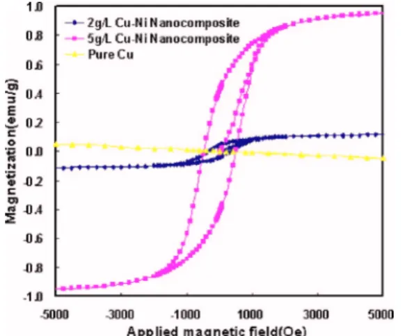
water then heated up to 40 ° C to drive IPA out of the water since IPA would block Cu seed layer surface for plating. Here, instead of conventional sulfuric Cu plating solution, the commercial alkaline noncyanide based copper plating solution17is chosen for the nanocomposite synthesis because the Ni particles will chemically react with acidic sulfuric copper plating solution. The reaction causes little Ni nanopo-wder incorporation in Cu matrix. By adjusting the amount of Ni nanoparticles being added into the solution, Cu–Ni mag-netic nanocomposites with different Ni incorporations can be synthesized. The composite plating rate is controlled at⬃0.2 m / min. While Cu is plated, well-dispersed Ni na-nopowders are engulfed in Cu matrix to form magnetic Cu–Ni nanocomposite. Figure 2 shows superconducting quantum interference divice 共SQUID兲 measurement. The magnetic property of Cu film is modified from diamagnetism to ferromagnetism via the incorporation of Ni nanoparticles and the Ms of Cu–Ni nanocomposite increases with the amount of Ni nanoparticles being added into plating bath.
A microstructure shown in Fig. 3 is fabricated for low-power scheme verification. The fabrication begins with 0.6m thermal oxide deposition, followed by 0.6m low-stress nitride deposition on a p-type silicon共p-Si兲 substrate. A diaphragm area driven by inductive coil is then defined and patterned from the back side of the silicon substrate via chemical wet etching using KOH. A 5m thick SU-8 film is then spun onto the etched substrate to form the actuated dia-phragm. After the diaphragm fabrication, a sandwich layer of Ti共10 nm兲/Cu 共120 nm兲/Ti 共5 nm兲 is evaporated and pat-terned to serve as a seeding layer for electroplating. The inductive coil is patterned then electroplated in the afore-mentioned Cu–Ni colloidal solution added with 2 g / l Ni nanopwoders to form a 2m thick magnetic Cu–Ni nano-composite coil. During the plating, the wafer is placed in a vertical fashion inside the bath with mechanical stirring at 120 rpm and the bath temperature is kept at 40 ° C. In order to ensure a uniform magnetic field laterally applied on the inductive coil, other conventional photolithography and elec-troplating processes18are performed for NiFe Permalloy ring fabrication. Finally, the silicon substrate is then bonded with a print circuit board共PCB兲 board using ALTECO adhesive to form a microcavity inside on which a 0.02 T magnet is mounted, as shown in Fig. 3共a兲. Figure 3共b兲 shows the top view of as-fabricated device.
Figure 4 shows the vertical displacements of the SU-8 diaphragms actuated by Cu and Cu–Ni nanocomposite coils, respectively. The displacement measurement is performed using an optical interferometer with subnanometer vertical resolution and calculated to be equal to the height difference of the point A shown in Fig.3共a兲while the coil is applied with and without an electric current input. Here, the height of FIG. 2. SQUID measurements of pure Cu and Cu–Ni nanocomposites
plated in a bath added with 2 and 5 g / l Ni nanopowders, respectively.
FIG. 3. 共a兲 Diagram of magnetic microactuation structure designed for the low-power scheme verification and共b兲 the top view of as-fabricated SU-8 diaphragm with magnetic Cu–Ni nanocomposite coil.
244105-2 Huang et al. Appl. Phys. Lett. 90, 244105共2007兲
This article is copyrighted as indicated in the article. Reuse of AIP content is subject to the terms at: http://scitation.aip.org/termsconditions. Downloaded to IP: 140.113.38.11 On: Thu, 01 May 2014 00:25:31
point A is referenced to a fixed point, called R, under which silicon substrate is not removed. Due to process variation, the power consumption is normalized by the thickness of inductive coil for fair comparison. From the measurement, it is found that, under the same input, the diaphragm driven by Cu–Ni composite coil can have a larger displacement while the displacement exceeds 10m. Under the same input of 4.67⫻10−7W m, the diaphragm driven by pure Cu coil has
22m vertical displacement which is 2m less than that driven by Cu–Ni nanocomposite coil. In other words, the coil made of magnetic Cu–Ni nanocomposite can exhibit better power efficiency for the same displacement. In addition, Fig.4also shows that Cu–Ni nanocomposite coil can make the SU-8 diaphragm have much larger displacement than the one made of pure Cu before the coils are failed.
According to Eq.共4兲, the power reduction scheme can be realized as long as the ratio of Pcomposite/ Pcis smaller than 1 and the proposed Cu–Ni nanocomposite is just fit into the role. With the assumption of isotropic magnetization of spherical Ni particles inside Cu matrix, Eq.共4兲 can be sim-plified as follows: Pcomposite/Pc=
冉
r,Cu 共r,composite兲冊
2k m kc . 共5兲The r,composite can be calculated based on the Bruggeman
approach19as follows since the added Ni particle size is very small: r,composite=Cu+共1 − fCu兲 ␣h Ni/Cu 1 −共1 − fCu兲共␣h Ni/Cu /3r,Cu兲 , 共6兲 ␣hNi/Cu= 3r,Ni r,Ni−r,Cu r,Ni+ 2r,Cu , 共7兲
where fCuis the volume ratio of Cu in the composite,␣hNi/Cu is the magnetizability density, andr,Cuandr,Niare relative permeabilities of Cu and Ni, respectively. For the case of Cu–Ni nanocomposite, r,Cu and r,Ni are 0.999 and 9,20 respectively. The r,composite can be modified from 1.21 to
2.46 while the volume fraction of embedded Ni particles is changed from 1% to 5%. Meanwhile, the value of km/ kc shown in Eq.共3兲is also changed from 1.015 to 1.079. Thus,
Pcomposite/ Pcwill theoretically fall in a range of 0.18 to 0.69. More than 18% power reduction could be realized. Never-theless, it is noted that the calculation of km/ kcratio is simply based on the electrical conductivities of Cu and Ni films. Since the electrical conductivity of metal particle could be smaller than that of metal film21and would result in a larger
km/ kcratio. Meanwhile, the size of Ni particles used here is about 50 nm in which the coercive force is around 250 Oe Ref.22 and is comparable with the magnetic field intensity of the bias magnet that we use in the device. Only part of Ni particles can be fully magnetized by the bias magnet. There-fore, it is reasonable that only 9% performance improvement has been observed so far. The characterizations of Cu–Ni nanocomposites and the Ni nanoparticle size and spin depen-dent scattering effects on the electrical conductivity of the composite are still required for further optimization for low-power magnetic microactuation design.
In summary, this letter presents a power consumption reduction scheme and verification using Cu–Ni nanocompos-ite. The approach can lead the way to further saving opera-tional power in the present magnetic microactuator designs. The Cu–Ni nanocomposite and related low temperature fab-rication process also show the potential applications for MEMS fabrications due to its CMOS process compatibility. This work was supported by the NSC 95-2220-E-009-021 project and in part by MediaTek Research Center at National Chiao Tung University.
1J. H. Ku, J. O. Chan, and Y. S. Sik, Proc. SPIE 3990, 272共2000兲. 2S. Bhansali, L. A. Lei, B. R. Zmood, P. E. Jones, and D. K. Sood,
J. Microelectromech. Syst. 9, 245共2000兲.
3J. Singh, A. Agarwal, and M. Soundarapandian, Thin Solid Films 504, 64
共2006兲.
4P. C. Shiang and W. Hsu, J. Micromech. Microeng. 7, 7共1997兲. 5D. Damjanovic, K. G. Brooks, A. Kholkin, M. Kohli, T. Maeder, P.
Muralt, and N. Setter, Mater. Res. Soc. Symp. Proc. 360, 429共1995兲.
6C. T. Panand S.-C. Shen, J. Magn. Magn. Mater. 285, 422共2005兲. 7C. H. Ahn and M. G. Allen, J. Micromech. Microeng. 3, 37共1993兲. 8D. de Bhailis, C. Murray, M. Duffy, J. Alderman, G. Kelly, and S. C.
Mathuna, Sens. Actuators, A 81, 285共2000兲.
9I.-J. Cho, T. Song, S.-H. Baek, and E. Yoon, IEEE Trans. Microwave
Theory Tech. 53, 2450共2005兲.
10D. Rajesh and L. Amit, J. Microelectromech. Syst. 14, 488共2005兲. 11B. Wagner, W. Benecke, G. Engelmann, and J. Simon, Sens. Actuators, A
32, 598共1992.
12H. J. Cho and C. H. Ahn, J. Microelectromech. Syst. 11, 78共2002兲. 13G.-R. Shen, Y. T. Cheng, and L.-N. Tsai, IEEE Trans. Nanotechnol. 4, 539
共2005兲.
14T.-Y. Chao and Y. T. Cheng, Proceeedings of the IEEE Conference on
Nanotechnology, 2006, p. 810.
15D. G. Han and G. M. Choi, Solid State Ionics 106, 71共1998兲.
16B. D. Cullity, Introduction to Magnetic Materials共Addison-Wesley, New
York, 1973兲, p. 191.
17M. Schlesinger and M. Paunovic, Modern Electroplating, 4th ed.共Wiley,
New York, 2000兲, p. 104.
18M.-C. Cheng, W.-S. Huang, and S. R.-S. Huang, J. Micromech. Microeng. 14, 859共2004兲.
19A. Lakhtakia and T. G. Mackay, AEU, Int. J. Electron. Commun. 58, 1
共2004兲.
20N. J. Tang, W. Zhong, W. Liu, H. Y. Jiang, X. L. Wu, and Y. W. Du,
Nanotechnology 15, 1756共2004兲.
21S. Singamaneni and V. Bliznyuk, Appl. Phys. Lett. 87, 162511共2005兲. 22Y.-W. Du, M.-X. Xu, J. Wu, Y.-B. Shi, H.-X. Lu, and R.-H. Xue, J. Appl.
Phys. 70, 5903共1991兲. FIG. 4. Vertical displacement of SU-8 diaphragms vs the normalized input
to the driving coils, which are made of Cu and Cu–Ni nanocomposite, respectively.
244105-3 Huang et al. Appl. Phys. Lett. 90, 244105共2007兲
This article is copyrighted as indicated in the article. Reuse of AIP content is subject to the terms at: http://scitation.aip.org/termsconditions. Downloaded to IP: 140.113.38.11 On: Thu, 01 May 2014 00:25:31