行政院國家科學委員會專題研究計畫 成果報告
高頻快速電子遷移電晶體吉柏特混頻器及除頻器
研究成果報告(精簡版)
計 畫 類 別 : 個別型 計 畫 編 號 : NSC 98-2221-E-009-031- 執 行 期 間 : 98 年 08 月 01 日至 99 年 07 月 31 日 執 行 單 位 : 國立交通大學電信工程學系(所) 計 畫 主 持 人 : 孟慶宗 報 告 附 件 : 出席國際會議研究心得報告及發表論文 處 理 方 式 : 本計畫可公開查詢中 華 民 國 99 年 06 月 24 日
行政院國家科學委員會補助專題研究計畫
█ 成 果 報 告
□期中進度報告
高頻快速電子遷移電晶體吉柏特混頻器及除頻器
計畫類別:■個別型計畫 □ 整合型計畫
計畫編號:NSC 98-2221-E-009-031
執行期間: 98 年 8 月 1 日至 99 年 7 月 31 日
計畫主持人:
孟慶宗 國立交通大學電機系
共同主持人:
計畫參與人員:蘇珍儀、吳政魁、林忠佑、吳彥鋒、張智凱
成果報告類型(依經費核定清單規定繳交):□精簡報告
■完
整報告
本成果報告包括以下應繳交之附件:
□赴國外出差或研習心得報告一份
□赴大陸地區出差或研習心得報告一份
■
出席國際學術會議心得報告及發表之論文各一份
□國際合作研究計畫國外研究報告書一份
處理方式:除產學合作研究計畫、提升產業技術及人才培育研究計畫、
列管計畫及下列情形者外,得立即公開查詢
□涉及專利或其他智慧財產權,□一年□二年後可公開查詢
執行單位:
國立交通大學電信系
中 華 民 國
99 年 6 月 15 日
附件一中文摘要─ 因為無線通訊系統發展迅速,快速電子 遷移電晶體製程仍然在微波和毫米波區段 使用。而許多使用CMOS 和矽鍺 HBT 技術 吉伯特混頻器大多都操作在低頻,然而在IC 技術上傳統以四分之一波常為基礎微波被 動元件占大部分面積,於是在這個計畫當 中,採用 HEMT 技術類比電路設計,同時 達到阻抗匹配實作。 首先,由於在半絕緣的GaAs 基板以及 先進的製術,所以 17GHz 吉伯特單級正交 降 頻 器 搭 配 多 重 相 位 濾 波 器 才 能 利 用 0.15-μm pHEMT 製程第一次地完美地呈現 出來。此外,利用0.15-μm mHEMT 設計 Q 頻段之次諧波吉伯特升頻器及兩個降頻搭 配多重相位濾波器也已實作出來了。會使用 次諧波混頻器是因為LO 頻率只需要 RF 頻 率的一半。此外,針對次諧波降頻器設計而 言,延遲補償技術可改善埠之間的隔離度。 另外,吾人利用ft=85 GHz 之 pHMET 製程 和ft=110 GHz 之 mHEMT 製程實作了訊號 再生式除二電路以比較其特性。
Abstract ─As the wireless communication system develops rapidly, high-electron mobility transistor technology is still used in the microwave and millimeter-wave regimes. Many Gilbert complex mixers have been realized using CMOS and SiGe HBT technologies, mostly at low frequencies. Whereas the traditional microwave passive components based on quarter-wavelength design concepts are not compact and consume the real estate in the IC technology, analog circuit design concepts are adopted using HEMT technology in this project than implementing impedance matching design approaches.
First of all, thanks to the semi-insulating GaAs substrate and an advanced technology, a 17-GHz Gilbert single-quadrature down- converter (SQDC) with polyphase filters is successfully demonstrated using 0.15-μm AlGaAs/InGaAs pseudomorphic HEMT (pHEMT) technology for the first time to the best of our knowledge. Besides, a Q-band sub-harmonic Gilbert up-converter and two down-converters with quadrature LO generation by polyphase filter are demonstrated using InAlAs/InGaAs metamorphic HEMT (mHEMT) technology. The sub-harmonic mixer (SHM) is employed because the LO frequency is only half of the
RF frequency. For sub-harmonic down- converter design, a delay compensation technique is employed to improve the port-to- port isolation. Further, divide-by-two quadrature regenerative frequency dividers (RFDs) are demonstrated using 0.15-μm pHEMT technology with 85-GHz cutoff frequency and 0.15-μm mHEMT technology with 110-GHz cutoff frequency.
關鍵字─降頻器、升頻器、次諧波混頻器、
多相位濾波器、快速電子遷移電晶體、訊號 再生式除頻器。
Index Terms─down-converter, up-converter, sub-harmonic mixer (SHM), polyphase filter, high electron mobility transistor (HEMT), regenerative frequency divider (RFD).
INTRODUCTION
The main goal of this research is to develop a Gilbert mixer and a frequency divider using GaAs-based HEMT technology in the microwave and millimeter-wave regimes.
Until now, HEMT technology has played a chief role in microwave and millimeter-wave circuits. The advantages of HEMT transistors, such as large transconductance, great power density, low noise figure, and high breakdown voltage, as well as a semi-insulating GaAs substrate are favorable for circuits operating at high frequencies. Today, the HEMT technology retains the world record for the cut-off frequency and maximum operation frequency (about 500-GHz ft and about 400-GHz fmax).
Nowadays, many Gilbert mixers have been realized using CMOS and SiGe HBT technologies at the low-frequency wireless systems. A Gilbert mixer has the advantages such as higher conversion gain, compact size and good isolation. Recently, the advancement in silicon device scaling has made CMOS and SiGe HBT Gilbert mixers possible even at millimeter-wave frequencies. On the other hand, with an advanced technology, the modern wireless communication system moves to higher frequency. HEMT technology is usually adopted in the microwave and millimeter-wave regimes. The indium mole fraction is 15 - 30% and 40% for pHEMT and mHEMT devices provided by the standard foundry process, respectively. Thus, a 0.15-μm InAlAs/InGaAs mHEMT technology has a 110-GHz cutoff frequency while a
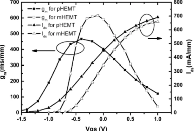
0.15-μm AlGaAs/InGaAs pseudomorphic HEMT (pHEMT) technology has an 85-GHz cut-off frequency. In Fig. 1, the measured dc transconductance (gm) and drain current (Ids)
are plotted as a function of gate voltage with Vds=1.5V for the 0.15 μm pHEMT and
mHEMT, respectively. The gm peaks around Vgs= -0.4 V with a value of 467 mS/mm for
the pHMET transistor and the mHEMT has a maximum gm of 616 mS/mm at Vgs= -0.1 V,
respectively. At Vds= 1.0 V, the pHEMT and
the mHEMT have a maximum drain current of 691 mA/mm and 660 mA/mm, respectively. The breakdown voltage of the pHEMT and mHEMT are 10 V and 8.6 V, respectively. Additionally, the process includes the metal-insulating-metal (MIM) capacitors (Cplate=0.39 fF/μm2), thin-film resistors (50
Ω/□), mesa resistors (150 Ω/□ for pHEMT and 180 Ω/□ for mHEMT), backside processing, via-hole etching, air-bridge and two metal layers.
Fig. 1. Measured drain-to-source current (Ids) and
tranconductance (gm) with respect to gate-to-source
voltage for both pHEMT and mHEMT.
These advantages favor the high-frequency analog Gilbert mixer design and overcome the low breakdown voltage in the device-scaling advanced silicon technology.
RC-CR polyphase filters are used to generate the differential quadrature signals needed by the complex Gilbert mixer. The integrated RC-CR polyphase filters can also replace the conventional bulky off-chip IF filters for image rejection. However, the RC-CR polyphase filters in CMOS and BiCMOS technologies were realized below 2 GHz because it is difficult to fabricate accurate small resistors and capacitors at high frequencies due to the Si substrate parasitic effect. Even with the electronic tuning, the complex Gilbert mixers based on the silicon technology can function up to 6 GHz only.
Furthermore, the parasitic effect caused by the Si substrate influences the performance seriously and is difficult to be controlled at higher frequencies. On the contrary, the GaAs-based technology has accurate thin film resistors, MIM capacitors and no parasitic substrate effect. Thus, the resistors and capacitors required for the polyphase filter can be implemented precisely in GaAs-based technology.
An SHM is a popular topology for the direct conversion receiver to prevent the self-mixing problem in the fundamental mixer. The local oscillator (LO) of the subharmonic mixer operating at half of the RF frequency alleviates the difficulty in generating a high frequency LO signal. In the past, millimeter-wave HEMT mixers are mostly realized using diode mixer and FET resistive mixer topologies. Recently, millimeter-wave Gilbert mixers using advanced silicon technology have been demonstrated recently. Thus, GaAs-based PHEMT technology with higher cut-off frequency, high breakdown voltage and semi-insulating substrate becomes the choice of the technology for the millimeter-wave Gilbert mixers.
The leveled-LO mixer can be potentially operated at higher frequency but needs a larger LO power. When a step voltage function is stimulated at the gate-source terminal, the drain output current is generated after a phenomenological time delay In other words, the I-V characteristic transfer function should be expressed in terms of VGS,
VDS and The output drain current follows
the terminal gate-source and drain-source voltages in an adiabatic way only if the operating radian frequency is much less than the reciprocal of the time delay In general, active circuits operate much slower than the time delay which is normally on the order of one-third of the transistor transit-time delay. Therefore, the transit-time cut-off frequency fT
is still a good practical indication to judge whether the quasi-static model is valid for the second harmonic frequency or not.
Besides, in a conventional stacked-LO SHM, a current phase delay occurs between the top and bottom mixing cells due to the finite time delay of the transistors. As a result, the isolation performance is degraded even if the LO signals are perfectly differential- quadrature. The LO/2LO leakage to the RF input port may mix with itself to generate an output dc offset to ruin the baseband signal. In
this project, SHMs w/ and w/o compensation are demonstrated using 0.15-μm mHEMT technology to validate the isolation improvement.
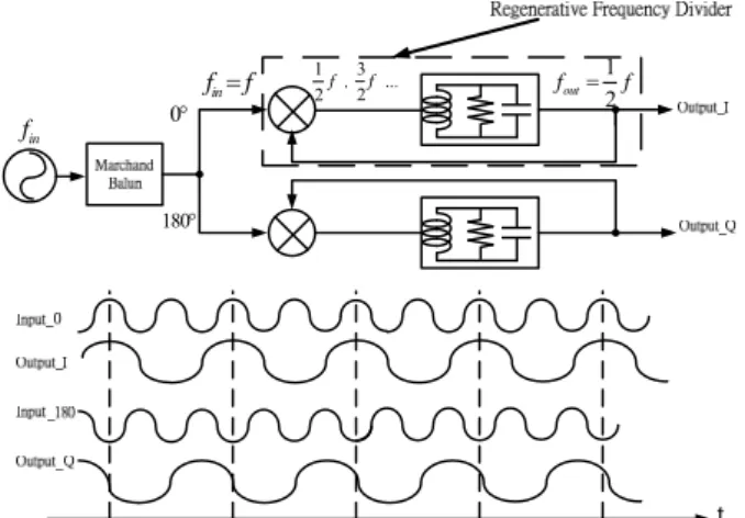
On the other hand, an RFD consists of a mixer, an amplifier and a low-pass filter (LPF) or a band-pass filter (BPF) as shown in the dotted area in Fig 2. The RFD’s output (1/2 fin)
is fed back to the mixer’s inputs (fin) and
results in the 1/2 fin mixing at a mixer’s output.
Other odd harmonic components (3/2fin,
5/2fin ..) can be filtered away by an LPF or
BPF. An RFD can achieve high speed, low power consumption, and low phase noise. In a direct conversion or low-IF systems, a frequency divider with quadrature outputs is usually needed. Papers about quadrature-output frequency dividers have been published. However, GaAs-based technology use the conventional microwave quarter-wavelength design concept for frequency dividers and thus the chip size is formidably large for the IC technology. Therefore, many GaAs-based dividers are usually differential outputs. Thus, in this project, the quadrature-output RFDs are demonstrated using 0.15-μm mHEMT and pHEMT technologies. The performance comparison of the two RFDs is also established.
RESEARCH METHOD AND DISCUSSIONS
(A) 17-GHz Single-Quadrature Down- Converter
1. Operational Principle
Figure 1 illustrates the functional block diagram of a SQDC with polyphase filters. The frequency of the input RF signal is denoted as RFLOIFand the frequency
of the image signal is denoted as
IM LO IF
. The meaning of the single quadrature means that the RF signal is real while the LO signals are in the quadrature format.
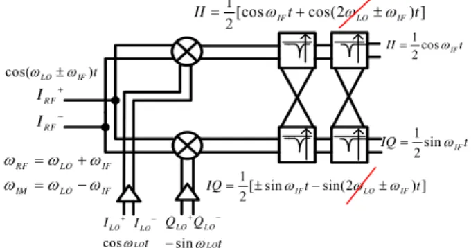
Two multipliers are employed to mix the RF signal and the image signal with the quadrature LO signals as shown in Fig. 2. There are totally 4 output IF signals resulting from the two multipliers. The differential quadrature IF signals consist of II+, IQ-, II- and IQ+ downconverted signals. Here, the first letter represents the constituent RF (IM) signal and the second letter represents the constituent LO signal for the composite IF
signal. The 4 downconverted IF signals can be grouped into differential quadrature signals as summarized in Table I. In each group, the differential quadrature IF signals, II+, IQ-, II- and IQ+, are in the counter-clockwise (positive)
sequence for the RFxLO mixing and in the clockwise (negative) sequence for the IMxLO mixing as shown in the Table I.
RF RF I I sin LO LO LO Q Q t cos LO LO I t cos(LOIF)t 1[ sin sin(2 ) ] 2 IF LO IF IQ t t 1[cos cos(2 ) ] 2 IF LO IF II t t LO I 1 cos 2 IF II t 1 sin 2 IF IQ t RF LO IF IM LO IF
Fig. 2 The functional block diagram of a SQDC. The low-pass property of the mixer’s IF output port eliminates the high frequency mixing components. Table I: The downconverted IF signals from mixing RF and image signals with quadrature LO signals (neglecting the high frequency components).
RF × LO IM × LO
II+ 0.5cosIFt 0.5cosIFt
IQ- 0.5sinIFt 0.5sinIFt
II- 0.5cosIFt 0.5cosIFt
IQ+ 0.5sinIFt 0.5sinIFt
The positive IF sequence can be treated as a positive IF+ frequency, ejIFt ; while the negative IF sequence can be treated as a negative IF- frequency, ejIFt . Thus, a polyphase filter which can discriminate the positive frequency from the negative frequency as shown in Fig. 2 is employed to achieve image rejection.
2. Mismatch effect on image rejection
Imperfect quadrature LO signals can be decomposed into an ideal sequence with an opposite error sequence as explained in reference. The imperfections in quadrature LO signals can be caused by feeding the unbalanced signals to the mixer and the mismatches in the mixer itself. The image rejection ratio degrades when non-ideal effects occur. When mismatches such as gain and phase errors occur, it is equivalent to say that the false signals at the negative spectrum appear. Thus, the mismatched quadrature LO signal can be represented as the linear combination of an ideal signal, LOID ( LO
j t
e ),
and the error signal, LOER ( j L Ot r
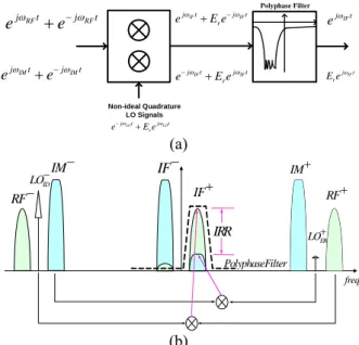
different sequence orientations as shown in Fig. 3(a). RF RF j t j t e e IM IM j t j t e e IF j t e IF j t r E e Non-ideal Quadrature LO Signals LO LO j t j t r e E e IF IF j t j t r e E e IF IF j t j t r e E e Polyphase Filter (a) PolyphaseFilter freq RF IM ER LO IF IF IM ID LO RF IRR (b)
Fig. 3 (a) The block diagram of a SQDC system with mismatch effect. (b) The spectra analysis of a SQDC with mismatch effect
Here,
LO LO
j t j t
ID ER r
LOLO LO e E e (1)
The term, Er, is the magnitude of the LOER
error signal normalized by the magnitude of the LOID ideal signal and is much less than
one. On the other hand, the real RF signal can be represented as the summation of two complex RF signals, i.e.
1 cos 2 j t j t RF RF RF t e e RF RF RF (2) In the following analysis, the factor of 2 is omitted to simplify the formula.
The degradation of the image rejection caused by mismatches can be easily analyzed using the complex signal representation. As shown in Fig. 3(a), the RF signal is multiplied with the LOID and the error LOER signals by two
mixers. The resulting IF signals after single-quadrature mixing can be represented as follows.
(2 ) (2 ) = +IF LO IF + LO IF + IF ID ER j t j t j t j t r r RF LO RF RF LO LO e E e e E e (3)The second and third terms can be filtered out directly by the low-pass function in the IF port of the mixer. As shown in Fig. 3(a), the polyphase filter can filter out the last term in Equation (3). Similarly, the resulting IF signals for the image signal after mixing can be represented as follows:
(2 ) (2 ) + LO IF + LO IF + IF IF ID ER j t j t j t j t r r IM LO IM IM LO LO e E e e E e (4)By the same token, only the fourth term ( j IFt
r
E e ) in Equation (4) with the same
frequency rotational sequence of the down-converted desired RF signal remains and is the error term. In other words, the error term, Er, in the mismatch quadrature LO is
directly passed to the downconverted IF+ signal through image signal. The diagrammatical explanation in signal spectra for finite image rejection caused by the mismatch effect is also shown in Fig. 3 (b). As a result, the image rejection ratio (IRR) is finite when mismatches occur.
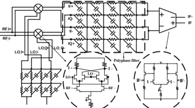
The schematic of the 0.15-μm pHEMT image-reject Gilbert SQDC is shown in Fig. 4. The Gilbert SQDC is composed of two Gilbert mixers, a two-stage polyphase filter at the LO stage, a four-stage polyphase filter at the IF stage and an IF buffer amplifier. External baluns are used to generate the required RF and LO differential signals. Thus, differential RF and differential LO signals are fed externally. As shown in Fig. 4, a two-stage polyphase filter is employed to generate the LO differential quadrature signals. The LO differential quadrature signals denoted as LO
I+, LO Q+, LOI- and LOQ- in Fig. 4 are applied
to the Gilbert cells of both mixers while differential RF signals are injected to the RF stages of mixers. The IF port of the mixer has a low-pass frequency response and thus the high frequency mixing components in Fig. 2 can be neglected. The mixed signals at the IF ports are arranged in the sequence of II+, IQ-, II-, and IQ+ when feeding to a four-stage RC-CR polyphase filter as shown in Fig. 4. It is important to notice that the sequences of the IF differential quadrature signals are different for the RF and IM signals as listed in Table I. The asymmetric IF RC-CR polyphase filter can pass one (RF) sequence and block the other (IM) sequence. Thus, the wanted RF signal can be obtained through the IF polyphase filter while the image-band unwanted signal is suppressed. However, mismatched effect causes finite image rejection because not only = j IFt
ID
RFLO e but
also j IFt
ER r
IMLO E e generates the positive
sequence and passes the IF polyphase filter as discussed earlier.
LO+ LO-RF_I+ RF_I-LO_I+ LO_I-LO_Q+ LO_Q-II + II-IQ+ IQ-IF IF- RF RF LO I I LO IF I I IF Polyphase filter
Fig. 4 Schematic of the pHEMT Gilbert SQDC with polyphase filters
Fig. 5 Photograph of the Gilbert SQDC with polyphase filters using depletion mode pHEMT technology.
A perfect image rejection can be achieved only at a single IF frequency for a one-stage IF polyphase filter even though there is no mismatch in the mixers. However, if a certain IF bandwidth is specified, a multi-stage IF polyphase filter needs to be employed and a finite image rejection ratio occurs even though there is no mismatch effect in the mixers. There is a trade-off between the image rejection ratio and the IF bandwidth in designing a polyphase filter. If a larger IF bandwidth and a higher image rejection ratio are desired at the same time, there must be more sections of polyphase filters in cascade. The polyphase filter can be cascaded to improve quadrature accuracy and expand the bandwidth; however, the performances of the gain and the noise figure are degraded. At the output of the polyphase filters, the in-phase (anti-in-phase) and quadrature-phase (anti- quadrature-phase) terminals are connected together to form the differential IF signals as shown in Fig. 4. A differential buffer amplifier is also included in the IF final stage as shown in Fig. 4. The gain performance can be easily further improved by inserting several IF amplifiers into the polyphase filter chain. The prototype downconverter in this paper
does not include this arrangement for the simplicity, but an IF output buffer amplifier is used at the end of the polyphase filters to provide some gain to compensate the loss of the IF polyphase filter.
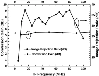
In this paper, the four-stage IF polyphase filter is designed to range from 10 to 90 MHz. The poles are located in a way to achieve a Butterworth response and the design renders a 40 dB image rejection ratio.
The microphoto of the pHEMT single-quadrature Gilbert down-conversion mixer with the LO and IF polyphase filters is shown in Fig. 5, and the die size is 2.3 mm×1.6 mm. The layout just has two metal layers for routings in GaAs technology. Additionally, the transmission line at high frequencies must be considered as a portion of the mixer design and the layout is kept symmetrically for better performance. The high-frequency LO and RF signal paths must be kept equal, respectively. The equal-path signal can reduce phase mismatch. The line-to-line coupling effect is more pronounced especially at high frequencies. When the width of a transmission line is smaller, the line-to-line spacing must be kept about 25-um distance to reduce the coupling effect and for better performance. The current consumption of mixer cores is 39 mA at the supply voltage VDD of 5.5 V. The measured results are based on 50 Ω systems and on-wafer probes. All performances are measured at one port of differential outputs, and the other port is terminated by a 50 Ω load. When LO input power equals 6.7 dBm at 17 GHz, the maximum conversion gain of the image rejection down-converter is about 5.5 dB as shown in Fig. 6. 2 4 6 8 10 12 14 16 18 -4 -2 0 2 4 6 RF=17GHz Conversion G a in (dB) LO Power (dBm)
Fig. 6 Conversion gain vs. LO power of the pHEMT Gilbert SQDC with polyphase filters
0 20 40 60 80 100 0 1 2 3 4 5 6 7 8 9 10 0 20 40 60 80 100 15 20 25 30 35 40
Image Rejection Ratio (d
B)
C
onversion Gain (dB)
IF Frequency (MHz)
Conversion Gain (dB)
Image Rejection Ratio(dB)
Fig. 7 Image rejection ratio and conversion gain vs. IF frequency for the pHEMT Gilbert SQDC with polyphase filters -35 -30 -25 -20 -15 -10 -5 0 5 10 15 20 -80 -70 -60 -50 -40 -30 -20 -10 0 10 20 IIP3=16dBm Out put Pow e r (dBm ) Input Power (dBm) Pout (f1) Pout (2f1-f2) IP1dB=0dBm
Fig. 8 One-tone and two-tone power performance of IP1dB and IIP3 for the pHEMT Gilbert SQDC with polyphase filters
The image rejection ratio is better than 30 dB from 10 MHz to 90 MHz as shown in Fig. 7. It is worth to mention that the polyphase filter is designed to have a minimum image rejection of 40 dB for IF frequencies from 10 to 90 MHz. Thus, the 30 dB image rejection ratio should come from the mismatch effect in mixers. Furthermore, the down-converter has 32-dB LO-to-RF, 40-dB LO-to-IF and 21-dB RF-to-IF isolations. Figure 8 depicts the performances of the input 1 dB compression point (IP1dB) and the input third-order
intercept point (IIP3). IP1dB and IIP3 of the
pHEMT Gilbert mixer equal 0 dBm and 16 dBm, respectively.
(B) 40-GHz Sub-Harmonic Up-Converter
A pHEMT transistor is a nonlinear device with square dependence between the drain current and the gate-source voltage. Compared with the stacked-LO sub-harmonic mixer, the leveled-LO structure uses the transistor’s nonlinearity. The leveled-LO-configuration is
shown in Fig. 9. The source-coupled differential pair (M1-M2, …, M7-M8) with the
drains connecting together as shown in Fig. 9 can eliminate fundamental signal and mostly the second harmonics appear at the drain terminals because of the quadratic relation between the drain current and gate-source voltage of the PHEMT. In other words, the square law dependence in pHEMT I-V curve lessens the LO power requirement.
LO_0 RF Vdd IF+ IF-LO_180 M1 M2 M3 M4 M5 M6 M7 M8 M9 M10 M11 LC Current Combiner RC Polyphase Matching Network L1 L2 C1
Fig. 9 Circuit topology of a 40 GHz subharmonic upconversion mixer using depletion mode AlGaAs/ InGaAs pHEMT technology
Figure 9 shows the schematic of the leveled-lo subharmonic upconversion mixer using depletion-mode pHEMT technology. The source-coupled pairs consisting of transistor pairs M1-M2 to M7-M8 form the
leveled-LO cell when their drains are connected together. If 0° and 180° differential input signals are injected into the leveled-LO M1-M2 and M7-M8 pairs, the fundamental
signals are eliminated by shorting the drains of the differential pair and only the even harmonic currents appear at the drain nodes. Simultaneously, 90° and 270° LO signals are injected into the leveled-LO M3-M4 and
M5-M6 pairs to generate the 2LO signal that is
out of phase to the 2LO signal generated by leveled-LO M1-M2 and M7-M8 pairs. The
transistor pairs M1-M2 to M7-M8 work
together to provide perfect 2LO differential signals. Consequently, this structure can be used for the sub-harmonic mixer, and these source-coupled leveled-LO pairs shown in Fig. 9 are able to double the LO frequency. By feeding LO signals with proper phases, the even harmonic leveled-LO structure can be employed to commutate RF currents at the rate of 2LO frequency.
An LC current combiner is employed at the RF output port. A two-stage LO polyphase filter is designed at the 20 GHz center frequency with 2 GHz bandwidth and about
5.2 dB loss. The subharmonic Gilbert mixer consists of subharmonic Gilbert cell (M1~M8),
the IF input stage (M9~M10) and the current
source (M11). A source resistor is used at the
source of M11 for self-biasing the current
source because only the depletion mode PHEMT devices are available. Thus, a single-voltage suppy for the upconverter is achieved. The differential quadrature signals needed by the subharmonic Gilbert cells (M1~M8) are generated by applying the
differential signals to the two-stage polyphase filter. An external 180o hybrid balun is employed to generate the differential LO signals and differential IF signals, respectively.
The inductors, L1 and L2, and a capacitor,
C1, form an LC passive current combiner
designed at 40 GHz (ω= 1/ 2L C1,2 1 ) at the RF output. An LC current combiner transforms the differential outputs of the sub-harmonic mixer into a single-ended output while doubling the voltage gain. In general, the performance of a passive LC current combiner at higher frequencies is superior to an active current mirror load because an active current mirror not only has a limited output voltage swing but also can not response rapidly at higher frequencies. Furthermore, a passive LC current combiner possesses good linearity. A short microstrip line with one end shorted is used as the inductor at 40 GHz. The microstrip line inductor has a good quality factor because GaAs-based technology has the backside ground plane and semi-insulating substrate. On the other hand, the high quality microstrip line inductor can not be realized in the Si-based technology because of the lack of the backside ground plane and the lossy silicon substrate.
Fig. 10 Micrograph of a 40 GHz subharmonic upconversion mixer using depletion mode AlGaAs/InGaAs pHEMT technology.
Figure 10 displays the micrograph of the
fabricated chip in Fig. 9. The layout is kept as symmetric as possible and the IF+ and IF
-inputs are located on the opposite sides for the sake of symmetry consideration. The chip size is 1.4 × 0.9 mm2 including pads. The supply voltage and total current is 4 V and 12.9 mA. When input LO power 9.5 dBm at IF = 0.1 GHz and LO = 20 GHz, the peak conversion gain has -1 dB. 37 38 39 40 41 42 43 -16 -12 -8 -4 0 4 C o nve rsi on Gain (dB) RF frequency (GHz) CG
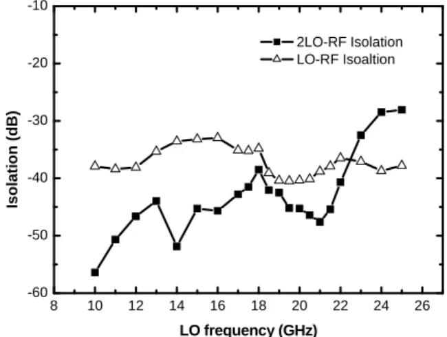
Fig. 11 Measured conversion gain versus RF frequency of a 40 GHz subharmonic upconversion mixer using pHEMT technology when LO frequency is fixed at 20 GHz. 8 10 12 14 16 18 20 22 24 26 -60 -50 -40 -30 -20 -10 2LO-RF Isolation LO-RF Isoaltion Is ol ati on (dB ) LO frequency (GHz)
Fig. 12 Measured LO-RF and 2LO-RF isolation of a 40 GHz pHEMT subharmonic upconversion mixer at the RF output port
The measured conversion gain versus RF frequency by fixing the LO frequency at 20 GHz and sweeping the IF frequencies is shown in Fig. 11. The experimental RF 3-dB bandwidth is about 1.8 GHz ranging from 39 GHz to 40.8 GHz and is limited by the LC current combiner and the associated output matching network. Meanwhile, in Fig. 12, the 2LO-RF isolation is better than 40 dB for 37 ~ 44 GHz LO frequencies and the IF-RF isolation is above 55 dB for 0.1 ~ 3 GHz IF frequencies. The LO-RF isolation is better than 40 dB for 19 ~ 20.5 GHz LO frequencies. The measured RF output return loss is shown
in Fig. 13.The RF output return loss is below -10 dB from 38.5 GHz to 41.4 GHz and -16.5 dB is achieved at 40 GHz. The output power performances of subharmonic upconverter are displayed in Fig. 14. The measured OP1dB
equals -20 dBm and OIP3 equals -5 dBm.
20 30 40 50 -20 -18 -16 -14 -12 -10 -8 -6 -4 -2 0 R F O u tp ut Re tun Lo ss ( d B ) Frequency (GHz) S22
Fig. 13 Measured RF output return loss of the pHEMT subharmonic Gilbert upconverter.
-35 -30 -25 -20 -15 -10 -5 0 -90 -80 -70 -60 -50 -40 -30 -20 -10 0 10 RF Ou tpu t P o w e r (d Bm) IF Input Power (dBm) Pf1 P2f1-f2 LO Power = 9.5 dBm LO Frequency = 20GHz IF Frequency = 0.1GHz
Fig. 14 Power performances of a 40 GHz subharmonic upconversion mixer using depletion mode AlGaAs/InGaAs pHEMT technology
(C) Q-Band Sub-Harmonic Down- Converter w/ and w/o Delay Compensation
As shown in Fig. 15(a), the stacked-LO core (Q1-Q8) consists of two pairs of Gilbert
mixing cells in cascode version with quadrature LO input, say, LOI at the top cell and LOQ at the bottom one. On the other hand, the compensation circuit (Qa1-Qa8) is a replica
of the stacked-LO core but LOQ/LOI are fed at the top/bottom cells, respectively, as shown in Fig. 15(b).
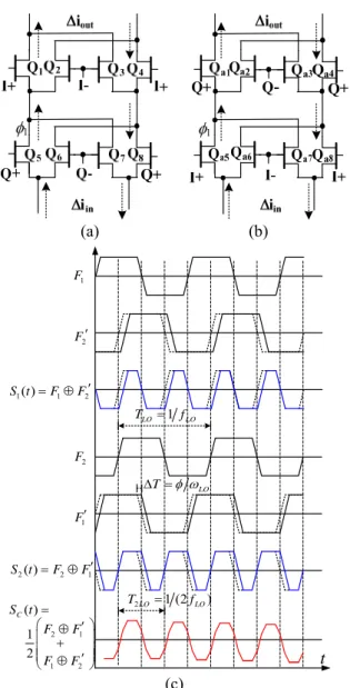
The switching mechanism of the stacked-LO core is illustrated in Fig. 15(c). F1(t)/F2(t) represent the switching function
with 0(I)/90(Q) LO input phase difference. Further, F1'(t) and F2'(t) represent the
switching function after a certain phase delay (). Therefore, the switching function of the stacked-LO core shown in Fig. 15(a) can be represented as S t1( )F1F 2 . On the other hand, S t2( )F2F1 represents the switching function of the circuit shown in Fig. 15(b). The switching function S1 or S2 does not have
a 50% duty cycle. If two stacked-LO cells with the same transistor sizes are in parallel, the equivalent switching function becomes
1 2
1 2 2 1 1 1 ( ) ( ) ( ) 2 2 C S t S t S t F FF F.(5)As shown in Fig. 15(c), a 50 % duty cycle is restored again for the compensated switching function (SC). The uncompensated
switching function S1(or S2) has an equivalent
dc term which results in an RF-to-IF leakage path while the compensated switching function (SC) does not.
(a) (b) 1 F 1 F 2 F 2 F 1( ) 1 2 S t FF 2( ) 2 1 S t FF 2 1 1 2 ( ) 1 2 C S t F F F F t 1 LO LO T f LO T 2LO 1 (2 LO) T f (c)
Fig. 15 (a) Schematic of the stacked-LO core with LOI/LOQ at the top/bottom cells (b) schematic of the stacked-LO core with LOQ/LOI at top/bottom cells (c) timing diagram of the switching function. Dotted lines represent the switching function without a phase delay, i.e., F1(t) or F2(t).
Fig. 17 Die photo of the Q-band mHEMT sub-harmonic mixers with delay compensation.
Fig. 18 Die photo of the Q-band mHEMT sub-harmonic mixers without delay compensation.
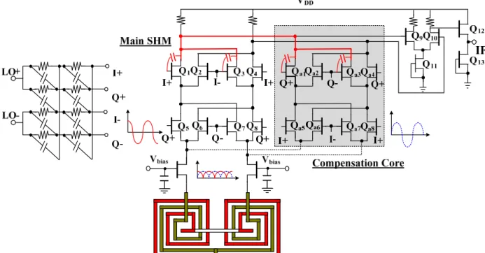
The schematic of Q-band SHMs w/ and w/o delay compensation is shown in Fig. 16. Ideally, the source node of a differential pair has large second-order harmonics as illustrated in Fig. 16; thus, the waveforms at the source nodes of the stacked-LO cores [Fig. 15(a) and (b)] are out-of-phase at twice the
LO frequency due to the 90° LO input phase difference at the bottom core. As a result, the two second-order harmonic terms can be cancelled if two circuits are in parallel. Thus, a higher 2LO-to-RF isolation is achieved. Similarly, the 2LO-to-IF isolation is also improved because (0°, 90°, 180°, 270°) LO leakage leaks to the same output and the 2LO frequency term can be cancelled as shown in Fig. 16. On the other hand, a double-balanced structure achieves better LO-to-RF/IF isolation performance than a single-balanced structure. However, any device mismatch may degrade the LO isolation.
Differential-quadrature LO signals are generated by a two-section polyphase filter from differential LO signals. Unlike the silicon-based technology, the GaAs-based technology has accurate thin-film resistors and metal-insulator-metal (MIM) capacitors. Therefore, the polyphase filter can be implemented at around 20 GHz with much accuracy.
Additionally, all the dc biases of the following mixer cores are fed from 2-kΩ resistors. On the other hand, an RF Marchand balun is used before common-gate configurations to generate differential signals as shown in Fig. 16. The dc ground of the mixer core is fed from the Marchand balun. Die photos of the SHMs w/ and w/o delay compensation are shown in Fig. 17 and Fig. 18 with the die sizes of 2.5×2 mm2 and 2×1.5 mm2, respectively. The supply voltage of each SHM is 7 V with the current consumption of 12 mA in mixer core, respectively.
37 38 39 40 41 42 43 44 45 46 -10 -5 0 5 w/ compensation w/o compensation Con versio n Gain (d B) RF Frequency (GHz)
Fig. 19 Conversion gain with respect to RF frequency of the Q-band mHEMT sub-harmonic mixers w/ and w/o delay compensation. 0 2 4 6 8 10 -20 -15 -10 -5 0 5 w/ compensation w/o compensation Conve rs ion G a in (dB) LO Power (dBm)
Fig. 20 Conversion gain with respect to LO power of the Q-band mHEMT sub-harmonic mixers w/ and w/o delay compensation. -25 -20 -15 -10 -5 0 5 -80 -70 -60 -50 -40 -30 -20 -10 0 10 w/ compensation Pout (f1) Pout (2f1-f2) w/o compensation Pout (f1) Pout (2f1-f2) O u tput Pow e r (d Bm) Input Power (dBm)
Fig. 21 Power performance at 39.1/42.1 GHz of the Q-band mHEMT sub-harmonic mixers w/ and w/o delay compensation.
Fig. 19 shows the RF bandwidth of the SHMs w/ and w/o compensation. The peak RF frequency of the compensated SHM is 39.2 GHz while the conventional stacked-LO SHM has a peak gain at 42.5 GHz. Fig. 20 shows the conversion gain as a function of LO power at fRF=39.1/42.1 GHz for SHMs w/ and
w/o compensation, respectively. About 2 dB more LO power is needed to overcome the
voltage loss in the polyphase filter of the compensated SHM due to a larger capacitive loading (i.e., mixer). The power performance of the SHMs w/ and w/o compensation is shown in Fig. 21 at fLO=19.5/21 GHz, fRF1=2fLO+fIF1, fRF2=2fLO1+fIF2, where fIF1=100
MHz and fIF2=110 MHz; thus, the IP1dB, and
IIP3 are 11/10 dBm, and /0 dBm,
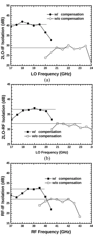
respectively. 17 18 19 20 21 22 23 24 20 25 30 35 40 45 50 2LO-IF Isolation (dB ) LO Frequency (GHz) w/ compensation w/o compensation (a) 17 18 19 20 21 22 23 24 25 30 35 40 45 2 L O-RF Is ola tion (dB) LO Frequency (GHz) w/ compensation w/o compensation (b) 37 38 39 40 41 42 43 44 15 20 25 30 35 40 45 w/ compensation w/o compensation R F -IF Iso latio n (dB ) RF Frequency (GHz) (c)
Fig. 22 (a) 2LO-to-IF isolation (b) 2LO-to-RF isolation (c) RF-to-IF isolation of the Q-band mHEMT sub-harmonic mixers w/ and w/o delay compensation.
As shown in Fig. 22(a), the 2LO-to-IF isolation of the SHMs w/ and w/o delay
compensation is 41/29 dB at fLO=19.5/21 GHz,
respectively. That is, a 12-dB improvement is achieved. Besides, the 2LO-to-RF is 37/32 dB and RF-to-IF isolation is 32/27 dB for the SHMs w/ and w/o compensation as shown in Fig. 22(b) and (c), respectively.
0.1 1 -6 -5 -4 -3 -2 -1 0 1 2 3 4 2 w/ compensation w/o compensation Conv e rsion Gain (dB) IF Frequency (GHz) 0.05 (a) 100 200 300 400 500 600 700 800 16 18 20 22 24 26 28 30 32 34 w/ compensation w/o compensation N o ise Figure (dB) IF Frequency (MHz) (b)
Fig. 23 (a) Conversion gain (b) noise figure with respect to IF frequency of the Q-band mHEMT sub-harmonic mixers w/ and w/o delay compensation.
As a result, the isolation improvement is valid. Moreover, the SHMs w/ and w/o compensation achieve conversion gain of 1/0.5 dB with 800 MHz IF bandwidth and double-sideband noise figure of 23/20 dB when fLO=19.5/21 GHz as shown in Fig. 23(a)
and (b), respectively.
(D) Divide-by-Two Quadrature Regenerative Frequency Divider
Two multipliers based on a double-balanced
Gilbert cell structure with self-feedback technique and a Marchand balun to drive the two multipliers in an anti-phase way form the quadrature-output RFD as shown in Fig. 24. The quadrature outputs come from the differential input driven and divide-by-two mechanisms and the waveforms are also
shown in Fig. 24. Figure 25 shows the corresponding schematic. A Marchand balun is composed of two back-to-back quarter-wavelength coupled lines.
0 180 in f f 12f 3 2f in f 1 2 out f f
Fig. 24 Block diagram and waveforms of a quadarture regenerative frequency divider which consists of two regenerative frequency dividers driven by a Marchand balun. VDD Input IF_I+ IF_I-IF_Q+ IF_Q-
Fig. 25 Schematic of the HEMT divide-by-two quadrature regenerative frequency divider
The input differential signal is applied to switching-pairs (M1-M2, …, M7-M8) and then
the feedback signal is injected into the differential-pairs (M9-M10, M11-M12). A
passive LC tank employed as a load of the divider is designed at a half of input frequency and also behaves like a band-pass filter. Although the division bandwidth becomes narrow, the supply voltage can be reduced by a passive LC tank. The inductor based on a short high-impedance microstrip transmission line has a high quality and is adopted here because GaAs-based technology has a semi-insulating substrate and backside ground process.
Figure 26 (a) and (b) show the photographs of the fabricated pHEMT and mHEMT quadrature RFDs, respectively. The die sizes are 1.9 mm × 1.8 mm for the pHEMT and 2.2 mm× 1.9 mm for the mHEMT dividers, and
those without a single-side band test structure and pads are 1.1 mm × 1.4 mm and 1.4 mm × 1.5 mm for pHEMT and mHEMT dividers, respectively. The measured results are based on on-wafer tests and 50 ohm instrument systems. The current consumption of the the pHEMT core has 28.4 mA at the supply voltage of 7 V while the mHEMT core consumes 16.9 mA at the supply voltage of 6V.
(a)
(b)
Fig. 26 The microphotos of quadrature regenerative frequency dividers using the depletion mode (a) AlGaAs/InGaAs pHEMT and (b) InAlAs/InGaAs mHEMT technologies.
Figure 27 and 28 show the experimental results for the output spectrum of the pHEMT and mHEMT dividers, respectively, by the Agilent E4448A spectrum. The output power of the mHEMT divider is 2~3 dB higher than that of the pHEMT divider. In Fig. 29, the best point of the minimum input sensitivity is 8.6 dBm at the 25.5-GHz input signal and 6 GHz division bandwidth from 22 GHz to 28 GHz is achieved for the pHEMT RFD. The lowest point of minimum input power is 7.6 dBm at 37.4 GHz and division range is from 36.5 GHz to 38.1 GHz for the mHEMT RFD as shown in Fig. 30. The phase noise of signal generators and divider outputs of the pHEMT and mHEMT RFDs are performed in Fig. 31 and 32. The phase noise of the divider
output is usually 6 dB better than that of the injected signal source.
Fig. 27 Spectrum for the 22~28 GHz pHEMT quadrature regenerative frequency divider.
Fig. 28 Spectrum e for the 36.5~38.1 GHz mHEMT quadrature regenerative frequency divider.
22 23 24 25 26 27 28 6 8 10 12 14 16 18 20 22 24
Min. Input Sensitivity for pHEMT Divider
Inp u t po wer (d Bm) Input frequency (GHz)
Fig. 29 Input sensitivity for the AlGaAs/InGaAs pHEMT quadrature regenerative frequency divider.
36.4 36.6 36.8 37.0 37.2 37.4 37.6 37.8 38.0 38.2 7 8 9 10 11 12 13 14 15 16 In put P o w e r ( dBm ) Input Frequency (GHz) Min. Input Sensitivity for mHEMT Divider
Fig. 30 Input sensitivity for the InAlAs/InGaAs mHEMT quadrature regenerative frequency divider.
CONCLUSION
In this project, we have demonstrated an SQDC image-rejection receiver, a 40-GHz sub-harmonic up-converter, Q-band sub- harmonic down-converter w/ and w/o delay compensation, and a divide-by-two quadrature RFD. The following are the performance summary of all the circuits.
(A) 17-GHz Single-Quadrature Down- Converter
For the first time to the best of our knowledge, a 17-GHz SQDC is demonstarted. From 10-MHz to 90-MHz IF frequencies, a 30-dB image rejection ratio is achieved when RF and LO frequencies are designed around 17 GHz. The Gilbert SQDC has a 5.5-dB conversion gain, 0-dBm IP1dB, and 16-dBm
IIP3.
(B) 40-GHz Sub-Harmonic Up-Converter The demonstrated PHEMT subharmonic Gilbert upconverter has a conversion gain of
-1 dB, an output return loss of -16.5 dB at 40 GHz, LO-RF isolation of 47 dB, and 2LO-RF isolation of 41 dB. OP1dB and OIP3 are -20
dBm and -5 dBm, respectively. The current consumption is 12.9 mA at a 4 V supply voltage.
(C) Q-Band Sub-Harmonic Down-Converter w/ and w/o Delay Compensation
SHMs w/ and w/o compensation achieve the conversion gain of 1/0.5 dB and noise figure of 23/20 dB when 2fLO=39/42 GHz.
However, the compensation circuit improves the 2LO-to-RF isolation by 12 dB, 2LO-to-IF isolation by 5 dB and RF-to-IF isolation by 5 dB without additional power consumption. (D) Divide-by-Two Quadrature Regenerative
Frequency Divider
The demonstrated 22~26-GHz pHEMT quadrature RFD consumes 28.4 mA at the supply voltage of 7 V while the 36.5~ 38.1-GHz mHEMT one consumes 16.9 mA at the supply voltage of 6V. The mHEMT divider has lower current consumption, high speed operation and output power as compared to the pHEMT divider. The outcomes offer another choice — the mHEMT analog circuit design approach in the fully integrated millimeter-wave regime.
REFERENCE
[1] S. Pinel, S. Sarkar, P. Sen, B. Perumana, D. Yeh, D. Dawn and J. Laskar, “A 90nm CMOS 60GHz radio,” ISSCC Dig. Tech. Papers, pp.130-601, Feb. 2008.
[2] Dehlink, B., Wohlmuth, H. D., Forstner, H. R., Knapp, H., Trotta, S., Aufinger, K., Meister, T. F., Bock, J., and Scholtz, A. L., “A highly linear SiGe double-balanced mixer for 77 GHz automotive radar applications,” IEEE Radio Frequency
Integrated Circuit Symp., 2006, pp.235-238.
[3] E. Martins, E. M. Bastida, and J. W. Swart, “Design and performance of a Gilbert cell mixer MMIC’s with a GaAs PHEMT Technology,” in
Proc. IEEE Microw. Optoelectron. Conf., Aug.
2001, vol. 1, pp. 245-248.
[4] C. F. Cambell, “A wideband pHEMT downconverter MMIC for satellite communication systems,” IEEE MTT-S. Int. Microw. Symp .Dig., pp. 55-58, 1998.
[5] F. Behbahani, Y. Kishigami, J. Leete and A. Abidi, “CMOS mixers and polyphase filters for large image rejection,” IEEE J. Solid-State Circuits, vol. 36, no. 6, pp.873-887, Jun. 2001.
[6] R. Magoon, A. Monlar, J. Zachan, G. Hatcher and W. Rhee, “A single-chip quad-band (850/900/1800/1900MHz) direct conversion GSM/GPRS RF transceiver with integrated VCOs and fractional-N synthesizer,” IEEE J .Solid-State Fig. 31 Phase noise of the 25-GHz pHEMT quadrature
regenerative frequency divider output and an input signal generator.
Fig. 32 Phase noise of the 37.5-GHz mHEMT quadrature regenerative frequency divider output and an input signal generator.
37.5GHz signal generator
18.75 GHz divider output 25 GHz signal generator
circuits, vol. 37, no. 12, pp. 1710-1720, Dec.
2002.
[7] D. I. Sanderson, R. M. Svitek and S. Raman, “A 5-6 GHz polyphase filter with tunable I/Q phase balance,” IEEE Microw. Compon. Lett., vol. 14, no. 7, pp. 364-366, Jul. 2004.
[8] C. Leifso and J. Nisbet, “A monolithic 6 GHz quadrature frequency doubler with adjustable phase offset,” IEEE J. Solid-State Circuits, vol. 41, no. 2, pp.405-412, Feb. 2006.
[9] C. C. Meng, D. W. Sung and G. W. Huang, “A 5.2-GHz GaInP/GaAs HBT double-quadrature downconverter with polyphase filters for 40-dB image rejection,” IEEE Microw. Compon. Lett., vol. 15, no. 2, pp. 59-61, Feb. 2005.
[10] Trantanella, C. J.: ‘Ultra-small MMIC mixers for K- and Ka-band communications’, in IEEE
MTT-S. Int. Microw. Symp .Dig., 2000, pp.
647-650.
[11] S. E. Gunnarsson, C. Kärnfelt, H. Zirath, R. Kozhuharov, D. Kuylenstierna, A. Alping and C. Fager, “High integrated 60 GHz transmitter and receiver MMICs in a GaAs pHEMT technology,”
IEEE J. Solid-State Circuits, vol. 40, no.
11, pp.2174-2186, Nov. 2005.
[12] S. Gunnarsson, K. Yhland and H. Zirath, “pHEMT and mHEMT ultra wideband millimeterwave balanced resistive mixers,” in
IEEE MTT-S Int. Microwave Symp. Dig., vol. 2,
Jun. 2004, pp. 1141-1144.
[13] B. Afshar, W. Yanjie and A.M. Niknejad, “A robust 24mW 60GHz receiver in 90nm standard CMOS,” ISSCC Dig. Tech. Papers, pp.182-605, Feb. 2008.
[14] B. Razavi, “A 60-GHz CMOS receiver front-end,”
IEEE J. Solid-State Circuits, vol. 41, no. 1, pp.
17-22, Jan. 2006
[15] T. H. Wu, S. C. Tseng, C. C. Meng and G. W. Huang, “GaInP/GaAs HBT sub-harmonic Gilbert mixers using stacked-LO and leveled-LO topologies,” IEEE Trans. Microw. Theory Tech., vol. 55, no. 5, pp. 880-889, May 2007.
[16] Gunnarsson, S. E., Gavell, M., Kuylenstierna, D., and Zirath, H.: ‘60 GHz MMIC double balanced Gilbert mixer in mHEMT technology with integrated RF, LO, and IF baluns’, Electron. Lett., 2006, 42, (24), pp.1402–1403.
[17] E. Dearn and L. M. Devlin, “A mm-wave monolitchic Gilbert-cell mixer,” IEEE Radio
Frequency Integrated Circuit Symp., pp.267-270,
2000,
[18] L. Sheng, J. C. Jensen, and L. E. Larson, “A wide-bandwidth Si/SiGe HBT direct conversion sub-harmonic mixer/downconverter,” IEEE J.
Solid-State Circuits, vol. 35, no. 9, pp. 1329–1337,
Sep. 2000.
[19] C. C. Meng, T. H. Wu and M. C. Lin, “Compact 5.2-GHz GaInP/GaAs HBT Gilbert upconverter using lumped rat-race hybird and current combiner,” IEEE Microw. Compon. Lett., vol. 15, no. 10, pp. 688-690, Oct. 2005.
[20] H. C. Jen, S. C. Rose, and R. G. Meyer, “A 2.2GHz sub-harmonic mixer for direct-conversion receivers in 0.13μm CMOS,” in IEEE Int.
Solid-State Circuits Conf. Dig. Tech. Papers, Feb.
2006, pp. 1840–1849.
[21] A. W. Buchwald, K. W. Martin, A. K. Oki, and K. W. Kobayashi, “A 6-GHz integrated phase-locked loop using AlGaAs/GaAs heterojunction bipolar transistors,” IEEE J. Solid-State Circuits, vol. 27, no. 12, pp. 1752–1762, Dec. 1992.
[22] J.-S. Syu, and C. C. Meng, “15-GHz high-isolation sub-harmonic mixer with delay compensation,” IEEE Microw. Wireless Compon.
Lett., to be published, Dec. 2009.
[23] H. Sjöland, A. Karimi-Sanjaani, and A. A. Abidi, , “A merged CMOS LNA and mixer for a WCDMA receiver,” IEEE J. Solid-State Circuits, vol. 38, no. 6, pp. 1045-1050, Jun. 2003.
[24] J.-Y. Su, S.-C. Tseng, C. C. Meng, P.-Y. Wu, Y.-T. Lee and G.-W. Huang, “Ka/Ku-band pHEMT Gilbert mixers with polyphase and coupled-line quadrature generators,” IEEE Trans.
Microw. Theory Tech., vol. 57, no. 5, pp.
1063–1073, May 2009.
[25] S. E. Gunnarsson, C. Kärnfelt, H. Zirath, R. Kozhuharov, D. Kuylenstierna, C. Fager, M. Ferndahl, B. Hansson, A. Alping and P. Hallbjorner, “60 GHz single-chip front-end MMICs and systems for multi-Gb/s wireless communication,” IEEE J. Solid-State Circuits, vol. 42, no. 5, pp. 1143 - 1157, May 2007.
[26] N. Marchand, “Transmission-line conversion transformers,” Electronics, vol. 17, no. 12, pp. 142–145, 1944.
[27] J.-S. Syu, C. C. Meng, and Y.-C. Yen, “5.7 GHz Gilbert I/Q downconverter integrated with a passive LO quadrature generator and an RF Marchand balun,” IEEE Microw. Wireless
Compon. Lett., vol. 18, no. 2, pp. 127-129, Feb.
2008.
[28] M. Mohktahri, C. H. Fields, R. D. Rajavel, M. Sokolich, J. F. Jensen, and W. E. Stanchina, “100+GHz static divide-by-2 circuit in InP-DHBT technology,” IEEE J. Solid-State Circuits, vol. 38, no. 9, pp. 1540-1544, Sep. 2003.
[29] K. Murata, T. Otsuji, E. Sano, M. Ohhata, M. Togashi, M. Suzuki, “A novel high-speed latching operation flip-flop (HLO-FF) circuit and its application to a 19-Gb/s decision circuit using a 0.2-μm GaAs MESFET, ” IEEE J. Solid-State
Circuits, vol. 30, no. 10, pp. 1101-1108, Oct.
1995.
[30] H. Ichhino, N. Ishihara, M. susuki, and S.Konaka, “18-GHz 1/8 dynamic frequency divider using Si bipolar technology,” IEEE J. Solid-State Circuits, vol. 24, no. 12, pp. 1723–1728, Dec. 1989.
[31] R. Adler, “A study of locking phenomena in oscillators,” Proc. IRE, vol. 34, pp. 351–357, June. 1946.
[32] H. R. Rategh and T. H. Lee, “Superharmonic injection-locked frequency dividers,” IEEE J.
Solid-State Circuits, vol. JSSC-34, pp. 813–821,
June 1999.
[33] A. Mazzanti, P. Uggetti, and F. Svelto, “Analysis and Design of Injection-Locked LC Dividers for Quadrature Generation,” IEEE J. Solid-State Circuits, vol. 39, pp. 1425–1433, Sep. 2004. [34] M. Zannoth, B. Kolb, J. Fenk, and R. Weigel, “A
Fully Intergrated VCO at 2GHz,” IEEE J.
Solid-State Circuits, vol. 33, pp. 1987–1991, Dec.
[35] C. Kärnfelt, R. Kozhuharov, H. Zirath and I. Angelov, “High-purity 60-GHz-band single-chip ×8 multipliers in pHEMT and mHEMT technology,” IEEE Trans. Microwave Theory
Tech., vol.54, no. 6, pp. 2887 - 2898, Jun. 2006.
[36] R. D. Miller, “Fractional-frequency generators utilizing regenerative modulation,” Proc. IRF, vol. 37, pp. 446-457, 1939.
[37] C. Kromer, G. von Büren, G. Sialm, T. Morf, F. Ellinger and H. Jackel, “A 40-GHz static frequency divider with quadrature outputs in 80-nm CMOS,” IEEE Trans. Microw. Theory
Tech., vol. 16, no. 10, pp. 564-566, Oct. 2006.
[38] S. Kudszzus, W. H. Haydl, M. Neumann, and M. Schlechtweg, “94/47-GHz regenerative frequency divider MMIC with low conversion loss,” IEEE J.
Solid-State Circuits, vol. 35, no. 9, pp.1312-1317,
Sep. 2000.
[39] L. Landén, C. Fager, and H. Zirath, “Renerative GaAs MMIC frequency dividers for 28 and 14
GHz,” 30th
European Microwave Conference,
2000, Oct.
[40] Z. Lao, W. Bronner, A. Thiede, A. Schlechtweg, A. Hülsmann, M. R. Motzer, G. Kaufel, B. Raynor, and M. Sedler , “35-GHz static and 48-GHz dynamic frequency divider IC’s using 0.2-um AlGaAs/GaAs-HEMT’s,” IEEE J. Solid-State
Circuits, vol. 32, no. 10, pp.1556-1562, Oct. 1997.
[41] S. C. Tseng, C. C. Meng, C. H. Chang, C. K. Wu, and G. W. Huang, “Monolithic broadband Gilbert micromixer with an integrated Marchand balun using standard silicon IC process,” IEEE Trans. Microwave Theory Tech., vol. 54, no. 12, pp. 4362-4371, Dec. 2006.
1 出國報告書 報告人姓名 孟慶宗 申請單位 (學生請加註系 級) 電機工程系 職稱 教授 電話 03-5131379 出國類別 □考察 □訪問 □進修 □研究 ■國際會議 □其他: 會議/出國計畫
名稱 IEEE Wireless and Microwave Technology (WAMI) Conference 2010
會議期間 自 99 年 4 月 12 日
至 99 年 4 月 13 日 出國地點 Melbourne Beach, Florida
報告內容包括: 一、 參加經過 二、 心得(可含照片) 三、 考察參觀活動(無是項活動者,或前已敘述者可省略此項) 四、 建議 五、 攜回資料名稱及內容 一、 參加經過
本次的 2010 年 IEEE Wireless and Microwave Technology Conference (簡稱 WAMICON)在 Florida 舉行。會期自 2010 年 4 月 12 日至 13 日。此會議之與會人士約為 150 人,雖然規模
不大,但是因為此會議的整體走向集中在高頻微波領域(包含被動電路、濾波器、天線、感測 器和功率放大器等),故聚集了不少微波領域的學者專家們。於是可以在此互相交流,讓此行 收穫更加豐碩。
吾人亦以論文“Comparison of Shunt-Series Shunt-Shunt and Shunt-Series Series-Shunt
Dual Feedback Wideband Amplifiers” 參加了此次的海報展示,亦引起不少人的興趣。經過
2 二、 心得(可含照片) 此會議之與會人士雖然人數不多,但兩天的議程卻相當緊湊,包含了微波領域之最新技 術之論文發表,以及請到知名之專家演說,可以藉此觀察及吸收到目前世界上微波領域的最 新發展。 不過有一點可以看得出來,各個地區或國家有不同的研究發展目標及方向,例如在主動 電路方面幾乎被台灣所包辦,這當然要感謝台積電(TSMC)和國家晶片系統設計中心(CIC)給 予整個學術界下免費 IC 的機會,而台灣區另一大宗則是被動電路的實作。現在西方國家也比 較偏向實際應用方面的研究。吾人認為,若是要讓研究的深度更加深,基礎的理論一定得再 加強,這樣研究的路才能走得更長更久。 以下為吾人於會議上展示海報時所拍攝之照片:
3 三、 考察參觀活動(無是項活動者,或前已敘述者可省略此項) 無 四、 建議 有來自各國研究人員參與此會議,和他們討論學到不少各公司或學校研究機構的詳細技 術,更了解最新的研究走向。故希望國內能夠大力資助本國研究人員參加此類會議。 五、 攜回資料名稱及內容 2010 WAMICON 之光碟(包含了議程及論文全文) 此次的會議議程包含了 Filter Sensors Power Amplifier
Circuit Integration & Techniques Antennas
Circuit Design Techniques RF MEMS
PA Large-Signal Design and Modeling Passive Circuits
4
Tutorial Session
Design and Performance of Microwave and Millimeter Wave High Efficiency Power Amplifiers
- Dr. James Komiak, BAE Systems
Present and Future Filter Design Philosophy: Paradigm Shift in Progress
- Dr. Richard Snyder, RS Microwave
Engineering and Measuring RF Waveforms -the Unifying Link Between System Performance, Circuit Design and Transistor Technology
- Prof. Paul Tasker, Cardiff University, UK
SDR Based Power Amplifiers / Transmitters for Advanced Wireless and Satellite Communications
- Prof. Fadhel Ghannouchi, University of Calgary, Canada
Fundamentals of Digital Radio: 0G through LTE and 4G