國
立
交
通
大
學
資訊科學與工程研究所
碩
碩
碩
碩
士
士
士
士
論
論
論
論
文
文
文
文
以 慣 性 量 測 元 件 為 基 礎
之 上 下 樓 層 人 體 行 為 辨 識 系 統
An IMU-Based Human Behavior Recognition
System for Upstairs and Downstairs Movement
研 究 生:吳宗衡
指導教授:曾煜棋 教授
中
中
中
中 華
華
華 民
華
民
民
民 國
國
國
國 九
九
九 十
九
十 九
十
十
九
九 年
九
年
年
年 九
九
九
九 月
月
月
月
以慣性量測元件為基礎之上下樓層人體行為辨識系統
An IMU-Based Human Behavior Recognition System
for Upstairs and Downstairs Movement
研 究 生:吳宗衡 Student: Tsung-Heng Wu
指導教授:曾煜棋 Advisor: Yu-Chee Tseng
國 立 交 通 大 學
資 訊 科 學 與 工 程 研 究 所
碩 士 論 文
A Thesis
Submitted to Institute of Computer Science and Engineering College of Computer Science
National Chiao-Tung University in partial Fulfillment of the Requirements
for the Degree of Master in Computer Science September 2010 Hsinchu, Taiwan
中華民國九十九年九月
i
以慣性量測元件為基礎之上下樓層人體行為辨識系統
學生:吳宗衡 指導教授:曾煜棋老師 國立交通大學資訊工程與科學研究所碩士班摘要
近年來,以無線射頻技術為基礎的室內定位系統在精準度上有不少的提升。然而,飄移 問題是造成定位誤差的一項重要因素。在多樓層定位中的飄移問題將造成不可接受的重 大誤差。因此,在本篇論文中,我們提出了一個以慣性量測元件為基礎之上下樓層人體 行為辨識系統。我們提出了數個創新的演算法,藉由比對目前特徵與訓練特徵來辨識人 體行為。利用我們的系統,多層樓定位系統可以在沒有改變樓層的人體行為發生時,將 定位結果鎖定在相同的樓層,藉此輔助定位結果的修正。如此一來,定位系統中樓層間 的飄移問題將得以解決。 關鍵字:慣性量測元件、人體行為辨識、高度偵測、室內定位、定位系統、肢體感測網 路、無線感測網路、特徵比對、最長共同子序列、最長共同子字串。An IMU-Based Human Behavior Recognition System
for Upstairs and Downstairs Movement
Student: Tsung-Heng Wu Advisor: Prof. Yu-Chee Tseng
Institute of Computer Science and Engineering National Chiao-Tung University
Abstract
The accuracy of RF-based indoor localization has been improved in recent years. However, drifting problem has been an important factor of causing localization inaccuracy. In multi-story indoor localization, drifting problem between floors is not acceptable. In this thesis, we propose a system to detect human behavior of changing floors, including elevator going up/down floors and going upstairs/downstairs using Inertial Measurement Unit (IMU) sensor. We proposed novel algorithms to recognize human behaviors by matching the current pattern with training patterns. By using our scheme, multi-story indoor localization systems are able to fix the positioning results in the same floor when no floor changing behaviors are detected. Therefore we are able to solve the drifting problem of changing floors.
Keywords: IMU, human behavior recognition, altitude detection, indoor localization,
positioning, body sensor network, wireless sensor network, pattern-matching, longest common subsequence, longest common substring.
Acknowledgements
Time and tide wait for no man. It is just like the day I came to Hsinchu and started my life as a graduate student. I remembered that Prof. Tseng asked me “what do you expect to learn in graduate school?” when I met him for the very first time. At that time, I just knew that I can learn more from advanced courses. But now, I have learned a lot not only from knowledge of taking courses, but also from doing research and working with others. I have tried really hard and now it is finally going to reach to an end.
First of all, I would like to give my special thanks to my advisor Yu-Chee Tseng, for instructing me and sharing innovative ideas with me. Also, I really appreciate all members of my team for teaching me and giving me opportunity to learn and work. Besides, I am grateful to all members in High Speed Communication & Computer Laboratory for supporting me and shar-ing joys and sorrows together. Moreover, I want to thank my friends in Hsinchu, who help me get accustomed to life here and have a lot of fun. Finally, this thesis would not have been possible unless the unconditional love and support from my family and I love you all. Thank everyone who has helped me throughout my studies. Computer science has always been my fa-vorite. I am hoping that this is not an end but a whole new start for my passion to my profession.
Mike Tsung-Heng Wu
Contents
Abstract i Acknowledgements iii Table of Contents iv List of Figures vi 1 Introduction 1 2 Related Works 3 3 Problem Definition 5 4 Observation 64.1 Choosing Meaningful Measurement: Acceleration Observation . . . 6
4.2 Choosing Meaningful Measurement: Euler Angles Observation . . . 8
4.3 Feature of Elevator Measurement . . . 9
4.4 Feature of Stairs Measurement . . . 10
4.5 Observation of Different Persons and Different Body Parts . . . 11
5 Methodology 15 5.1 System Architecture . . . 15
5.2 Hardware: IMU Sensor Measurement . . . 17
5.3 Software I: Training Phase . . . 17
5.3.1 Data Filtering . . . 17
5.3.2 Training Pattern Formation I: Pattern Segmentation . . . 18
5.4 Software II:Online Phase . . . 22
5.4.1 Data Filtering & Current Pattern Formation . . . 23
5.4.2 Behavior Detection I: Pattern Matching . . . 23
5.4.3 Behavior Detection II: Longest Common Substring . . . 26
5.4.4 Behavior Detection III: Longest Common Subsequence . . . 26
5.4.5 Detection Trigger . . . 26
6 Implementation and Experimentation 28 6.1 Design Decisions . . . 28 6.1.1 LPF Parameter . . . 28 6.1.2 Segmentation Parameters . . . 29 6.1.3 Trigger Boundary . . . 29 6.1.4 Discrete Factor . . . 29 6.2 Implementation . . . 30 6.2.1 Hardware . . . 30 6.2.2 Software . . . 30 6.3 Experimentation . . . 30 6.3.1 Experimental Environment . . . 30 6.3.2 Experimental Results . . . 31 7 Conclusion 35 Bibliography 36
List of Figures
4.1 Observation of Acceleration: Elevator. . . 7
4.2 Observation of Acceleration: Stairs. . . 8
4.3 Observation of Euler Angles: Elevator. . . 9
4.4 Observation of Euler Angles: Stairs. . . 10
4.5 Observation of Elevator. . . 11
4.6 Observation of Walking Downstairs. . . 12
4.7 Observation of Walking Upstairs. . . 13
4.8 Observation of Different Persons. . . 13
4.9 Observation of Different Parts of Human Body. . . 14
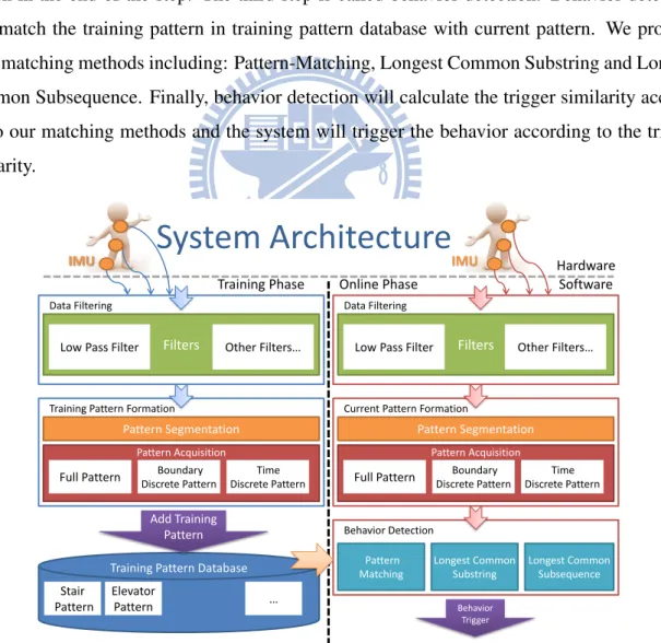
5.1 System Architecture. . . 16
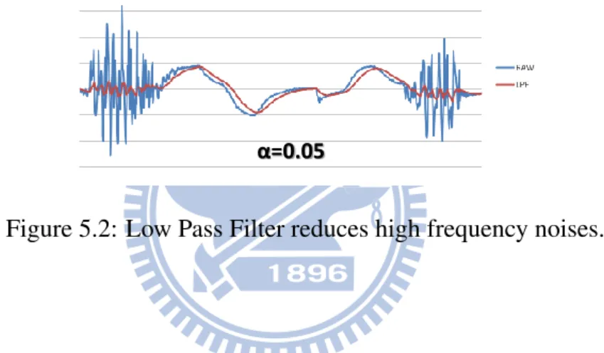
5.2 Low Pass Filter reduces high frequency noises. . . 18
5.3 Example of Discrete Factor and Discrete Level. . . 20
6.1 IMU Sensor: 3DM-GX1. . . 30
6.2 IMU Sensor: Different Part of Body. . . 31
6.3 Graph: Performance of Elevator Detection. . . 32
6.4 Graph: Performance of Stairs Detection. . . 33
Chapter 1
Introduction
Recently, indoor positioning has been more and more popular. Unlike outdoor positioning, in-door positioning cannot use GPS and often need to deal with multi-story environment. GPS signal cannot be received indoors, so that other positioning methods using RF signal are pro-posed. Most widely used positioning method using RF signal is Wifi positioning with NNSS [1]. However, RF signal is not stable and changes with time and environment. This will cause the estimated location drift with time even when the user is static, and we call this type of prob-lems, Drifting Problem. In indoor positioning, multistory environment is very common. How-ever, drifting problem between floors is not acceptable since this will cause huge error distance. Therefore, the knowledge of current floor is important to indoor positioning.
To obtain the current floor information, some method are proposed. In [15, 18], Barometer are used to detect the current height, and then calculate the current floor. However, atmosphere pressure changes with time and it need reference point to calculate the relative height. In addi-tion, barometer is not built-in in most mobile devices, and extra hardware are needed with extra cost.
There are more and more mobile devices with Wifi and Inertial Measurement Unit (IMU) built in. Also, IMU is frequently used as pedometer or step counter. In order to take advantage of built in sensors, we may use IMU to detect human behavior of changing floors to obtain the current floor information. While users are not doing any behavior of changing floors, the users will be lock on the same floor to avoid drifting problem between floors. In the other hand, if users are performing some behavior of changing floor, our system will change the users’ floor according to the behavior user performs. This way, the drifting problem between floors can be solved.
The rest of the thesis is organized as follows. Chapter 2 expresses the related works of our method. Chapter 3 defines the problem we are solving. Chapter 4 shows our observation of this work. We explain our detailed approach in Chapter 5. Chapter 6 illustrates how we design our approach and demonstrates the performance of our system. Chapter 7 concludes the thesis.
Chapter 2
Related Works
Our work is related to works of the following two categories: Pedestrian dead reckoning Inertial Navigation System(PDR INS) and altitude detection. Inertial navigation system is a navigation system using IMU. Pedestrian dead reckoning is to estimate one’s current position based on a previously determined position. Altitude detection is to detect the current altitude of user lo-cated. In Pedestrian dead reckoning inertial navigation system [2–6, 8–12, 14, 17, 19, 21–23], mostly are using IMU to detect movement. Initially, there’s an initial location obtained by all possible positioning method such as GPS, Wifi Positioning or even manually input. Human moves using their legs and legs swing when walking, so for every step moves, an estimation will be made based on previous move. This way, the first important part for PDR is pedometer or step counter using IMU. This part is well-developed and its accuracy is high. However, for movement estimation, step count is not the only information needed. User’s heading direction and length of every step are also required. By using magnetometer, direction can be easily ob-tained, but the magnetometer can be easily affect by the environment and will cause errors. The most difficult part is the estimation of step length. Accelerometer is used to estimate the distance of a step move. However, accelerometer is used to estimate length by double integration, and it will cause huge cumulative error. This way, a method called zero-velocity update (ZUPT) [19] is introduced. ZUPT resent the velocity of the user to zero when every step is performed since every time the foot steps on the ground, the velocity becomes zero. ZUPT can reduce the er-ror caused by the double integration of acceleration and has erer-ror with linear degree of time. The works of PDR inspires our work of detecting the movement of human. However, the most different part is that our work detects the movement of changing floors. Step length is not our concern but the vertical direction. Also, our main purpose is to assist localization system, not
to replace it, therefore, our goal is to recognize the event of upstairs and downstairs movement, which is different from PDR systems that focus on the location. In altitude detection, IMU [7] and barometer [13,15,18] are used to measure height changes. Same as PDR using IMU for step length, IMU can also be used for vertical movement. By using double integration of vertical acceleration, height changes can be obtained. However, problem of high cumulative error still exists. The strength of this method is that no extra hardware needed but the accuracy is low. On the other hand, barometer can also be used to detect height changes by measuring atmosphere pressure. Atmosphere pressure changes with altitude. For every 100 meter height increase, atmosphere pressure will decrease 8 mmHG. However, atmosphere pressure also changes with time, so we are only able to obtain the relative altitude by two atmosphere measurement and a reference point is needed in the infrastructure for obtaining current height. Also, in [18], it says that atmosphere pressure tends to change in indoor environment. Even opening the door of a room will cause the measurement of atmosphere pressure changing. This way, although IMU and barometer provide solutions to detect altitude changes, the accuracy is not satisfactory. In our system, we use IMU to avoid extra hardware cost and avoid directly calculating length from acceleration to avoid cumulative error.
Chapter 3
Problem Definition
In this chapter, we will define the problem we are solving. We will first make assumptions of our problem, and then describe the input and output of the problem. Finally, we will show our goal of solving this problem. In this problem, we assume that users are in the indoor envi-ronment of building with several stairs and elevators. Users are equipped with an IMU sensor and mobile device for running our system. IMU sensors we are using include accelerometer and magnetometer. Mobile Devices are including notebook, smart phone and so on. The in-put of this problem is the IMU measurements from IMU sensor. IMU measurements include 3-axis acceleration and Euler angles. These measurements are put into the system continuously. The output of this problem is the behavior system detected including walking upstairs, walking downstairs, taking elevator upstairs and taking elevator downstairs. For stairs, step of walking upstairs or downstairs will also be output. For elevator, the number of floors of elevator moves will also be output. The goal to solve this problem is to detect the human behavior of upstairs and downstairs movements in an accurate way. By achieving this, we are able to use this system to assist positioning system for better location estimation.
Chapter 4
Observation
IMU to detect human behavior of changing floors, we need to do several observations of human behavior of changing floors by using IMU sensor. IMU sensors often consist of accelerometer, magnetometer and gyro. Accelerometer is able to measure the 3-axis accelerations so that the movement of the measured object can be acknowledged. Magnetometer along with accelerom-eter is able to measure the Euler angles, which consist of roll, pitch, yaw, representing 3-axis degree of the pose of the measured object. Gyro is able to measure the 3-axis angular accel-erations so that the relative pose changing of measured object can be obtained and this is also helpful to obtain the Euler angles with higher precision. However, gyro is optional for obtain-ing the Euler angle. In this section, we will first do the observation of acceleration. Then, we will do the observation of Euler angles. By the two observations above, we will then see the observation of elevators and the observation of stairs and present what measurements of IMU are useful in our system for behavior detection. Finally, we will show that different persons and different parts of the body may also apply to our system during our observation. We do our observation with the IMU located in our waist with the same person. Then, in the section of Different Persons and Different Parts, we do our observation with different persons with the IMU located on waist. Then, we do our observations with the IMU located on waist and foot of a person.
4.1
Choosing Meaningful Measurement: Acceleration
Ob-servation
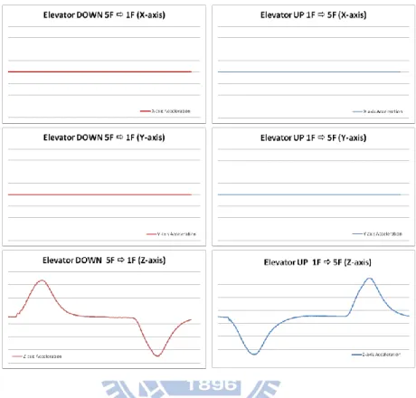
In the acceleration observation as Fig. 4.1 and Fig. 4.2, we have three measurements: X-axis Ac-celeration, Y-axis Acceleration and Z-axis acceleration. These measurements are representing
the acceleration of three orthogonal directions. By recording the measurements of the Accel-eration of a person taking elevator going up, going down, walking upstairs and downstairs, we are able to see how acceleration measurements change during the trajectory. When a person is
Observation of Acceleration
No Significant
Pattern
No Significant
Pattern
Pattern
Found!!
Elevator
Figure 4.1: Observation of Acceleration: Elevator.
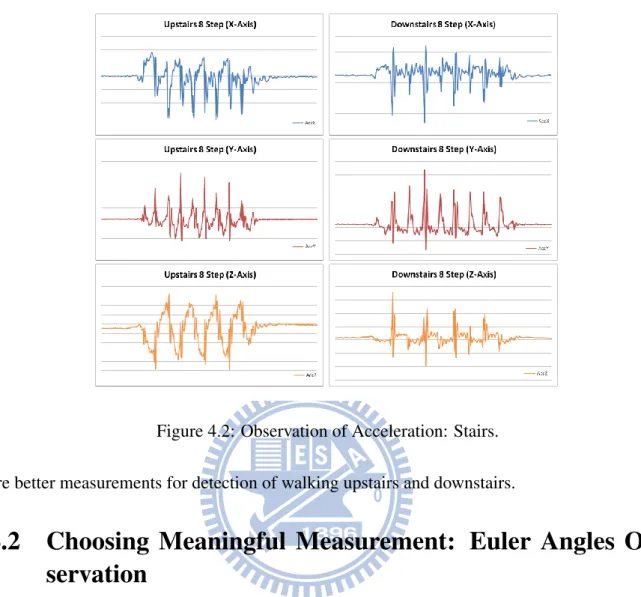
taking elevator going up and going down, we find that the X-axis and Y-axis of acceleration is almost zero all the way from the start to the end. This is due to the absent of horizontal move-ment when we taking an elevator. However, we can see that in the Z-axis of acceleration, we find a curve with concave up, straight vertical line and concave down when elevator is going up and a curve with concave down, straight vertical line and concave up when elevator is going down. This shows that the elevators accelerate at first and keep the constant velocity and finally decelerate. This is meaningful and clear enough to recognize the patter. Therefore, the Z-axis acceleration may be useful of detecting the behavior of taking an elevator. When a person is walking upstairs and downstairs, the curves of acceleration of all 3 axis are repeated over time. However, in the axis of X and Y, the curves of walking upstairs and walking downstairs are sim-ilar to each other. This is not desired when we are detecting the behaviors since this will easily cause the ambiguous situations. Also, in the axis of Z, the curve may be useful, but the curve is too complicated and with lots of noise, so we can turn into the Euler Angle to see whether there
Observation of Acceleration
Stairs
Not very
Significant
and not clear
Too similar to
each other
Significant but
still not clear
Figure 4.2: Observation of Acceleration: Stairs.
are better measurements for detection of walking upstairs and downstairs.
4.2
Choosing Meaningful Measurement: Euler Angles
Ob-servation
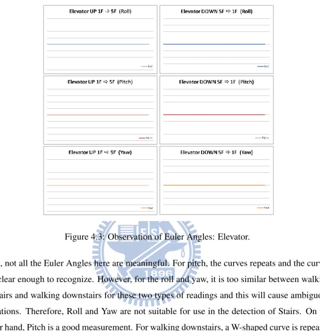
In the Euler angles observation as figure Fig. 4.3 and Fig. 4.4, we have three measurements: roll, pitch and yaw. These three measurements represent the degrees of rotation of an measured object along X-axis, Y-axis and Z-axis separately. We also record the measurement of the Euler angles of a person taking elevator going up, going down, walking upstairs and downstairs, we are able to see how the Euler angle measurements change during the trajectory. When a person is taking elevator going up and down, we find out that all the three axes keep the same value during the trajectory from the start to the end. This is because when you take an elevator, you are not changing the pose at all. You’ll stand all the way in static through the movements. Therefore, Euler angles are not meaningful to the behavior of elevator. When a person is walking upstairs and downstairs, we find that all Euler angles have measurements changing over the movements. This is because our poses keep changing over time when we are walking upstairs and downstairs. Although all Euler Angles have readings changing with
Observation of Euler Angle
No Significant
Pattern
No Significant
Pattern
No Significant
Pattern
Elevator
Figure 4.3: Observation of Euler Angles: Elevator.
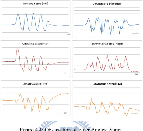
time, not all the Euler Angles here are meaningful. For pitch, the curves repeats and the curves are clear enough to recognize. However, for the roll and yaw, it is too similar between walking upstairs and walking downstairs for these two types of readings and this will cause ambiguous situations. Therefore, Roll and Yaw are not suitable for use in the detection of Stairs. On the other hand, Pitch is a good measurement. For walking downstairs, a W-shaped curve is repeated over time, and for walking upstairs, a U-shaped curve is also repeated over time. This way, we find out that the Pitch value is meaningful for the detection of stair behavior.
4.3
Feature of Elevator Measurement
In elevator observation, we can conclude from the observation of acceleration and Euler angle that vertical acceleration is the most meaningful measurement for the elevator detection. As Fig. 4.5, for the movement of an elevator going up, the graph of vertical acceleration and time will be concave up at first, vertical straight line in the middle and concave down in the end meaning that acceleration to the direction of up at first, constant velocity in the middle and deceleration in the end. For the movement of an elevator going down, the graph will be similar
Observation of Euler Angle
Significant but
not as clear as
pitch
Clear and
Significant
Pattern
Not Very
Significant and
similar to each
other
Stairs
Figure 4.4: Observation of Euler Angles: Stairs.
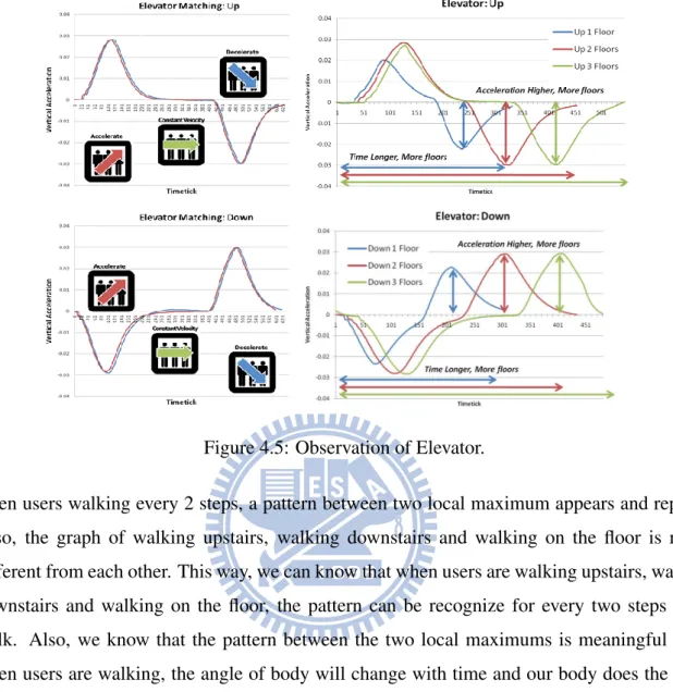
but the direction is in the opposite way. Also, we find out that for the same elevator, when the elevator is going up or down for more floors, not only the time of movement gets longer but also the peak value of the acceleration and deceleration. This feature enables us to not only detect the direction of the elevator, but also the number of floors elevator moves. This way, in the graph of vertical acceleration and time, we know that when the concave up, vertical straight and concave down appears, it’s the movement of elevator going up, and when the concave down, vertical straight and concave up appears, it’s the movement of elevator going down. Also, when the time and the peak value of concave grow, we know that the elevator is moving more floors. Therefore, in the following section, we are able to design a method to detect not only the direction of the elevator but also the number of floors the elevator moves.
4.4
Feature of Stairs Measurement
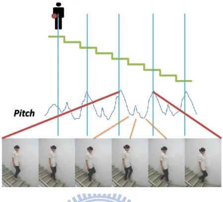
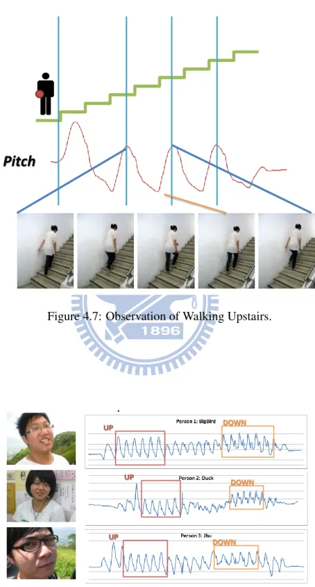
In stair observation, we can conclude from the observation of acceleration and Euler angles that the measurement of pitch of the Euler angles is the most suitable measurement for detection the behavior of walking stairs. As Fig. 4.7 and Fig. 4.6, for the movement of walking upstairs, walking downstairs and working on the floor, the graph of pitch value and time shows that
Observation of Elevator
Figure 4.5: Observation of Elevator.
when users walking every 2 steps, a pattern between two local maximum appears and repeats. Also, the graph of walking upstairs, walking downstairs and walking on the floor is really different from each other. This way, we can know that when users are walking upstairs, walking downstairs and walking on the floor, the pattern can be recognize for every two steps users walk. Also, we know that the pattern between the two local maximums is meaningful since when users are walking, the angle of body will change with time and our body does the same behavior over time repeatedly, and the local maximum will be the point that the users start and end the behavior. Therefore, in the following section, we are able to design a method to detect the behavior of the user’s movement of walking upstairs, walking downstairs and walking on the floor and the number of behaviors of every two steps has performed by users.
4.5
Observation of Different Persons and Different Body Parts
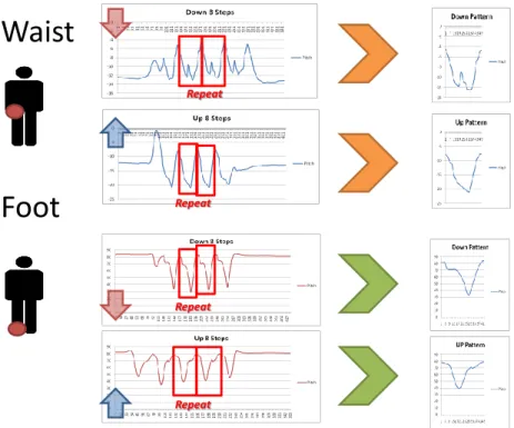
In our observations, we also make observations on different persons and different body parts of a person to make sure we can have more generic observations. In order to verify our observation on various persons, we perform the same observation on different persons. According to the observation, we can see that even different person perform the same behavior, the patterns of walking upstairs, walking downstairs and walking on the floor are similar among several persons
Observation of Stairs
Pitch
Figure 4.6: Observation of Walking Downstairs.
as as Fig. 4.8. Also, in order to make sure that using the measurement we use in Elevator Observation and Stairs Observation can also detect the same behaviors when IMU is put in different parts of body, we performs the observation on different part of human body. According to the observation, we can see that the patterns of walking upstairs, walking downstairs and walking on the floor are different from each other even when IMU is put in different parts of body as as Fig. 4.9.
Observation of Stairs
Pitch
Figure 4.7: Observation of Walking Upstairs.
IMU on Different Persons
• Waist for example: Similar to each other
UP DOWN
UP
DOWN
UP
DOWN
IMU on Different Parts of Human Body
• Waist
• Foot
Wais
t
Repeat Repeat Repeat RepeatChapter 5
Methodology
We propose a system for human behavior detection using IMU sensors. In our system, we focus on the human behavior detection of changing floors. Mostly, the human behaviors of changing floors are taking elevator upwards and downwards, and walking upstairs and downstairs. This system is composed of two major parts: hardware and software algorithms. Hardware part mainly consists of IMU sensors. Software algorithm part includes training phase and online phase. We assume that there are several IMU sensors on the user’s body. First, we need training phase to obtain the training patterns of human behaviors in advance and save these patterns into training pattern database. Then, when user starts to use our system, we use our online phase. In online phase, we gather the measurement data from the IMU sensors of the user and then pass the data filtering module for noise reduction. Then we process the input data to current pattern by the current pattern formation module. Finally, the behavior detection module matches the current pattern with the training patterns in training pattern database, and the behavior detection module will output the behavior trigger similarity. The system will then trigger detection based on the trigger similarities. In this section, we will first introduce our system architecture. Then, we will introduce the components of our system orderly including IMU Sensor Measurement, Training Phase and Online Phase. We will explain our methods in considering of Elevator Detection and Stairs Detection.
5.1
System Architecture
In our system there are two major parts: Hardware and Software. The Hardware Part is mainly about IMU sensors. IMU sensors are hanged on the user body to detect the pose and movement of human body. The Software Part consists of two major phases: Training Phase and Online
Phase. In Training Phase, there are two major steps: data filtering and training pattern forma-tion. Data filtering is to pass filters to reduce noises and errors. Training pattern formation is to form a training pattern by segmenting meaningful part of measurement and convert the data into patterns for further use in online phase. Training Data Formation consist of two steps: pat-tern segmentation and patpat-tern acquisition. Patpat-tern Segmentation is to cut the continuous IMU measurements automatically into meaningful segments. Pattern Acquisition is to convert the meaning segments into several types of training patterns for online use. In online phase, there are three major steps: data filtering, current pattern formation and behavior detection. The first two steps are the same as the training phase but the IMU measurement is from the user using our system for behavior recognition online. For the first two steps, we can obtain the current pattern in the end of the step. The third step is called behavior detection. Behavior detection is to match the training pattern in training pattern database with current pattern. We propose three matching methods including: Pattern-Matching, Longest Common Substring and Longest Common Subsequence. Finally, behavior detection will calculate the trigger similarity accord-ing to our matchaccord-ing methods and the system will trigger the behavior accordaccord-ing to the trigger similarity.
System Architecture
Behavior Trigger
Training Pattern Database Matching Pattern Longest Common Substring Longest Common Subsequence Training Phase Filters Hardware Software Add Training Pattern
Low Pass Filter
Online Phase
Filters
Low Pass Filter Data Filtering
Training Pattern Formation
Data Filtering
Current Pattern Formation
Behavior Detection
IMU
Pattern Segmentation Pattern Segmentation
IMU Stair Pattern Elevator Pattern … Pattern Acquisition Boundary Discrete Pattern Time Discrete Pattern Full Pattern Pattern Acquisition Boundary Discrete Pattern Time Discrete Pattern Full Pattern
Other Filters… Other Filters…
5.2
Hardware: IMU Sensor Measurement
In our system, IMU sensors are placed on the three different place of human body. We put them on the chest, the waist and the foot. The IMU sensor on the chest is put on the front pocket of the shirt. The IMU sensor on the waist is tied on the belt of pants. The IMU sensor on the Foot is stuck on the ankle. We measure the vertical acceleration and pitch readings from the IMU sensors simultaneously. Then, we forward these readings from IMU sensors to our behavior detection algorithm of both elevator detection and stairs detection. In elevator detection, we use the measurement of vertical acceleration, and in stairs detection, we use the measurement of pitch.
5.3
Software I: Training Phase
Training phase is to obtain the features of human behaviors in advance for further detection. We call the features of human behaviors training pattern. After we obtain the training patterns, we add them into the training pattern database. Training pattern database is a database containing the training patterns obtained from the training process. These data represents the behaviors and will be used for matching in online phase. We have two steps in this process: data filtering and training pattern formation. Firstly, data filtering is to do filtering in order to reduce noise, such as low pass filter. Then, we will obtain and segment the measurements into the feature of human behaviors from observation. Finally, we form a training pattern by defining the pattern and the method of transforming into a desired pattern. In the following, we introduce the three steps of Training Processes and explain them in both elevator detection and stairs detection.
5.3.1
Data Filtering
Filtering step is to process the data we obtain from IMU sensors. In this step, we process the data in order to reduce the noise of data and transform the data into the form that will be used in training pattern formation step.
Elevator Detection
In the data filtering step of elevator detection, we process our patterns by low pass filter(LPF). low pass filter can be addressed as following equation:
a0i := α × ai+ (1 − α) × a0i−1 (5.1)
aiis the i-th element before LPF processing. a0iis the i-th element after LPF processing. a 0 i−1is
the (i-1)-th element after LPF processing. α is a parameter controlling the frequency to be cut off. We use low pass filter to filter out the high frequency noise. During our observation, since frequency of walking is much higher than the frequency of elevator’s movement, we can filter out the noise which walking may make as in Fig. 5.2.
Training Phase – Data Filtering
• Low Pass Filter (Optional)
– Eliminate the noise from walking.
a’
i:= α × a
i+ (1-α) ×a’
i-1• Other Filters, such as High Pass Filter (Optional)
α=0.05Figure 5.2: Low Pass Filter reduces high frequency noises.
Stair Detection
In the data filtering step of stair detection, according to the observation, the stair behavior mea-surement of pitch value is clear enough so that no filtering is needed in stair detection.
5.3.2
Training Pattern Formation I: Pattern Segmentation
Pattern segmentation step is to obtain the useful data for determining specific human behaviors. In this step, we focus on what measurement should be used and what should be obtained for detection.
Elevator Detection
In the pattern segmentation step of elevator detection, we use the vertical acceleration measure-ment to obtain the all combination of the elevator’s moving pattern. For example, if there’s an elevator which can move from the first floor to the third floor, we then record the up 1 floor pat-tern, up 2 floor patpat-tern, down 1 floor pattern and down 2 floor pattern. During our observation,
the elevator moving up 1 floor will all be similar when the floor height is the same. However, during the case of different floor heights, more patterns will be needed. For example, same as the elevator in the previous example, we need the pattern up from first floor to second floor and the pattern up from the second floor to third floor instead of the up 1 floor pattern in the previous example. We record patterns of every elevator we need to detect.
Stair Detection
In the pattern segmentation step of stair detection, we use the pitch measurement to obtain the features used in stair detection. In this step, we obtain three types of human behavior related to stair detection including walking upstairs, walking downstairs and walking on the floor. During our observation, we find out that the pattern between two local maximum which will repeat when the same behavior is performing. This way, the repeat pattern is the feature we want to gather in this step. To obtain a more general pattern, we will do the same behavior for several times and average them. We will have a deeper look in Pattern Formation step of averaging patterns.
5.3.3
Training Pattern Formation II: Pattern Acquisition
Pattern acquisition step is to define a pattern and describe the method we use to form a pattern. In order to be used in behavior detection of online phase, we have three type of patterns: full pattern(FP), boundary discrete pattern(BDP) and time discrete pattern(TDP).
Full Pattern
Elevator Detection In pattern acquisition step of elevator detection, we have two type of patterns: full Pattern and half detection parameters. To form a full pattern, we first define a training pattern TBehavior = {a1, a2, ..., ak} with dynamic size of k. Element ai of TBehavior is
the i-th measurement of vertical acceleration in the training pattern of specific Behavior. We directly use the measurements from the data filtering step with no further process. To retrieve the half detection parameters, we also use the patterns from data filtering step. However, we use only the beginning concave of patterns of elevator going up and elevator going down since the target of half detection is for early detection without knowing the number of floors moved. This way, we need to obtain the length LU P, LDOW N and the sum SU P, SDOW N of vertical
as the beginning concave of elevator going up. We choose the shortest movement of elevator to get these parameters. For example, if there is an elevator which can move from the first floor to third floor. We record the length and sum of the elevator moving only one floor up and down. This is because during our observation, the concave grows larger when it travels more floors. This way, we only need to obtain the smallest one as boundary.
Stair Detection To form a full pattern, we first define a training pattern TBehavior = {p1, p2, ..., pk}
with dynamic size of k. Element pi of training pattern is the i-th measurement of pitch
mea-surement in the training pattern of specific Behavior. We use the meamea-surements from data filtering step. In order to get a generic pattern, we need to average the pattern. To average the patterns, we need to interpolate the patterns of the same Behavior to the length of kmax the
longest pattern, and then we average them to generate the desired generic training pattern of the behavior.
Boundary Discrete Pattern
In order to obtain boundary discrete pattern, we need to transfer measurement into discrete way, we first get the maximum value DM AX and the minimum value DM IN of each pattern. Then,
we separate the range between DM AX and DM IN into several subrange by discrete factor DF .
For example, let DF = 5, we can separate the the value between DM AX and DM IN into 5
subrange. As Fig. 5.3, we define Discrete Level that define the Lowest subrange be 1 and define the Highest subrange be 5 as discrete factor DF . Now for every measurement in the pattern, we can transfer every measurement to discrete level. This way, we can transform every pattern into the discrete form. To form a boundary discrete pattern, we first define a discrete training
Training Phase – Training Pattern Formation
(2) Pattern Acquisition
b. Boundary Discrete Pattern
– Define a T’={d
1,d
2,…,d
n}
– Initial: Empty
– Element d
i: i
thElement of T’ /
Discrete Level
– Add Discrete Level to T’ when
Discrete Level Changes
3 2 1 2 3 2 1 2 3 4 5 4 5 Discrete Factor β
The # of distinct level between
Minimum and Maximum of a
pattern. Discrete Level Minimum =1 Maximum= β 5 Maximum Minimum 1 2 3 4 T’ 5 4 3 2 1 2 3 2 1 2 3 4 5 Discrete Factor β =5 Discrete Level
Figure 5.3: Example of Discrete Factor and Discrete Level.
of discrete level in the full pattern of specific Behavior. We use the measurements from data filtering step. Now, we want to obtain a sequence called boundary discrete pattern TBehavior0 from the discrete training pattern. The Discrete Level Sequence Pattern is empty in the begin-ning and we add the first discrete level of a discrete traibegin-ning pattern into the sequence. Then, from the second element to the last element, we only add the discrete level into the sequence when the discrete level is different from the previous one. The detailed obtaining algorithm is described in Algorithm 1.
Algorithm 1 Sequence Obtaining Algorithm of Boundary Discrete Pattern Input: DT PBehavior
Output: TBehavior0 1.Initial
TBehavior0 → N U LL
Add d1 of DT PBehaviorinto TBehavior0 .
Let LastInsert = d1.
2.Loop:
for i = 2 to k do
if LastInsert 6= dithen
Insert di into TBehavior0 .
Set LastInsert = di.
else
Continue. end if end for
By Algorithm 1, we can obtain the boundary discrete pattern TBehavior0 of each behavior. Finally, we put these patterns into the training pattern database for further matching use.
Time Discrete Pattern
To form a time discrete pattern, we also use discrete training pattern introduced previously. Then we want to obtain a sequence called time discrete pattern TBehavior00 . This time discrete pattern is different from the previous one. We add a time constraint, time lasting factor β to the sequence obtaining algorithm with consideration of time domain. While the previous algorithm insert the discrete level only when the discrete level changes, the algorithm in this method insert the discrete level when the discrete level changes or when the discrete level keep the same at a
certain length of time set by time lasting factor. The detailed algorithm is described in Algorithm 2.
Algorithm 2 Sequence Obtaining Algorithm of Time Discrete Pattern Input: DT PBehavior, β
Output: TBehavior00 1.Initial
TBehavior00 → N U LL
Add d1 of DT PBehaviorinto TBehavior00 .
Let LastInsert = d1.
Let T imer = 0.
2.Loop:
for i = 2 to k do
if LastInsert 6= dithen
Insert di into TBehavior00 .
Set LastInsert = di.
Set T imer = 0. else if T imer > β then
Insert di into TBehavior00 .
Set T imer = 0. else
Continue. end if end for
By Algorithm 2, we can obtain the time discrete pattern TBehavior00 of each behavior. Finally, we put these patterns into the training pattern database for further matching use.
5.4
Software II:Online Phase
Online phase is to obtain the current pattern and match with training pattern to determine whether the similarity is high enough to trigger the behavior. We have three steps in this pro-cess: data filtering, current pattern formation and behavior detection. Firstly, data filtering is to filter the noise from the current IMU measurement. Then, we will obtain the current pattern from the current IMU measurement by segmenting the meaningful parts and transfer into useful data structure. Finally, we use behavior detection methods to match current pattern with training patterns. Behavior detection methods will then calculate the trigger similarity and the system
will trigger the behavior according to the trigger similarity. In the following, we introduce the three steps of online process and explain them in both elevator detection and stairs detection.
5.4.1
Data Filtering & Current Pattern Formation
In online phase, data filtering is totally the same with training phase. Current pattern pattern formation is almost the same as training pattern formation but the input measurement of IMU is from the current realtime user measurement for behavior recognition.
5.4.2
Behavior Detection I: Pattern Matching
Elevator Detection
In elevator detection, our methods are to detect the elevator is going up or down and how many floors is the elevator going up or down. In order to detect both, we propose our pattern matching method. However, pattern matching only detects when the elevator completes its movement. This way, we propose our half detection in order to detect whether the elevator is going up or down in the half way, so that we are able to detect the elevator’s behavior in the middle of the elevator’s movement, but this method is not able to detect how many floors are the elevator moved. Therefore, with the combination of pattern matching and half detection, we are able to detect the direction of elevator’s movement in the half way and determine the number of floors the elevator moving.
Pattern Matching In the pattern matching, we use the full pattern from the training process. Then, we define a current pattern C = {a1, a2, ..., an} with the constant windows size n, and n
is set to the maximum length of training pattern for further matching use. Element aiof training
pattern is the vertical acceleration measurement value at time i. For every new input from IMU sensor, we add the newest value to the end of the current pattern, and remove the oldest value in the front of the current pattern.
Finally, we start to match current pattern with training patterns. For every training pattern, we calculate the error distance between current pattern and the training pattern by the following equation:
For every Behavior, ErrDist(C, TBehavior) = k X i=1 |Cn−k+i− TBehavior,i| (5.2)
After we calculate the error distance of current pattern and every training pattern, we can trigger the detection by the trigger boundary(TB). We define trigger boundary T BBehavior as a value
for a elevator behavior to trigger the detection.
Algorithm 3 Full Pattern Detection Algorithm Input: TBehavior, C
Output: T riggerSimilarity
for every TBehavior do
Calculate ErrDist(C, TBehavior)
if (ErrDist(C, TBehavior) < TBehavior) then
T riggerSimilarity = 100%. else T riggerSimilarity = TBehavior ErrDist(C,TBehavior). end if end for
As Algorithm 3, by using pattern matching, we are able to detect the elevator behavior with direction and number of floors and output the behavior trigger similarity to detection trig-ger. However, the detection can be triggered only when the movement of elevator is complete. Therefore, we propose half detection method to solve this problem.
Half Detection In half detection, we use half detection parameters from the training process. half detection parameters include the length LU P, LDOW N and the sum SU P, SDOW N. Now we
use the current pattern C from pattern matching. For elevator detection of going up, we use the LU P and SU P. We define U pSU M (C) as following:
U pSU M (C) =
LU P
X
i=1
(Cn−LU P+i) (5.3)
Also, for elevator detection of going down, we use the LDOW N and SDOW N. We define
DownSU M (C) as following: DownSU M (C) = LDOW N X i=1 (Cn−LDOW N+i) (5.4)
After we calculate U pSU M (C) and DownSU M (C), we can trigger by comparing the value of U pSU M (C), SU P and DownSU M (C), SDOW N. If U pSU M (C) is larger than SU P, up
detection triggers, and if DownSU M (C) is larger than SDOW N, down detection triggers.
Algorithm 4 Half Detection Algorithm Input: C Output: T riggerSimilarity if U pSum > SU P then T riggerSimilarityU P = 100%. else T riggerSimilarityU P = U pSumS U P %. end if if DownSum > SU P then T riggerSimilarityDOW N = 100%. else
T riggerSimilarityDOW N = DownSumS
DOW N %.
end if
As Algorithm 4, by using half detection, we are able to trigger the elevator detection of up and down in the half way of elevator movement. Therefore, half detection can assist pattern matching to have the early detection while pattern matching provides higher accuracy and the number of floors going up or down.
Stairs Detection
In the pattern matching, we use the training pattern T in full pattern from training process as training pattern. Now we define a current pattern C = {p1, p2, ..., pn} with the dynamic
windows size n, and n is set to the length between two local maximum. In order to avoid the constant shift problem caused by the IMU unit, we need to do the shifting to make sure the patterns we are going to match are on the same baseline. This way, we shift the pattern to its average as following equation:
P atternshif t= P attern − Average(P attern) (5.5)
Then we can obtain the shifted patterns T and C. The length of each pattern is different, so we need to transfer the patterns into the same length. This way, we do the interpolation to expend the shorter pattern to the same size as the longer pattern. Finally, we can calculate the Error
Distance by the following equation: ErrDist(C, TBehavior) = k X i=1 |Cn−k+i− TBehavior,i| (5.6)
Then, we can use Algorithm 3 to output the behavior trigger probability.
5.4.3
Behavior Detection II: Longest Common Substring
In the longest common substring, we use the boundary discrete pattern (BDP) from training process as training pattern. First, we construct a current pattern of boundary discrete pattern C’ as T’ in training process. Now we have two boundary discrete patterns from training process and online process. Then, we use the longest common substring algorithm to calculate the length of longest common substring |LCS|. Then we can calculate the trigger similarity between these two patterns as following equation:
Similar(T0, C0) = 2 × |LCStr(T
0, C0)|
|T0| + |C0| (5.7)
By calculating the trigger similarity, we can take this similarity and output it to the detection trigger.
5.4.4
Behavior Detection III: Longest Common Subsequence
In the longest common subsequence [20], we use the time discrete pattern (TDP) from training process as training pattern. First, we construct a current pattern of time discrete pattern C” as T” in training process. Now we have two time discrete pattern from training process and current pattern. Then, we use the longest common subsequence algorithm to calculate the length of longest common subsequence |LCS|. Then we can calculate the similarity between these two patterns as following equation:
Similar(T00, C00) = 2 × |LCSeq(T
00, C00)|
|T00| + |C00| (5.8)
By calculating the trigger similarity, we can take this similarity and output it to the detection trigger.
5.4.5
Detection Trigger
Detection trigger collects the trigger similarities from the online phase of each IMU sensors. According to these data, the detection trigger will process these data with the weighted factors
of each behavior to trigger the final detection behavior. The final detection result will be made in this part.
Chapter 6
Implementation and Experimentation
In this chapter, we will talk about how our design decisions are made. In order to apply the method into the real world, we need to choose parameters and make decisions from tradeoffs. Also, we will explain how we implement our system. Finally, we will show our experimental results.
6.1
Design Decisions
In our system, design decisions are made to make our system work in the real world properly. These decisions are based on the method we propose and the empirical experience in observa-tion and experiments. Parameters are tuned to make our system work in the best way. In the following, we present how we make decisions through the important parameter in our system, including LPF parameter, segmentation paramters, trigger boundary, and discrete factor.
6.1.1
LPF Parameter
Low pass filter can filter out the high frequency noise. In our system, LPF is used to filter out the relatively high frequency noise of walking movement and retain relatively low frequency pattern of elevator movement. α is the parameter controlling the boundary of frequency to be filter out. We choose this α parameter based on the experiment. We walk in the elevator when the elevator is moving. Then, we use LFP with different α value to test whether the walking noise is significant or the elevator movement pattern is also filtered out. After several tests, we find out that LPF works best in our system when the parameter α is 0.05.
6.1.2
Segmentation Parameters
Segmentation parameters are used in our system when segmenting IMU measurements into patterns. Patterns of elevator are segmented when a pair of concave up and concave down is found. To detect the concave up and concave down, we have to obtain the time length cont
and maximum conmaxor minimum value conminof the smallest concave in elevator movement.
This way, when a concave with enough time length and exceed or below the maximum or minimum value of the smallest concave, a concave up or concave down is recognized and when a pair is obtained, segment will be done. In the other hand, patterns of stairs are segmented by two local maximum. However the local maximum is not only the local maximum we mentioned in our system, but also with some conditions. We define our local maximum to be a local maximum when a local maximum value happens after a time period localt and the value over
the time period fall below a boundary localf. This is made to prevent the small oscillations of
our pattern to cause the wrong segmentation.
6.1.3
Trigger Boundary
Trigger Boundary of a pattern is a boundary to trigger the behavior of the pattern based on the experience. This parameter must choose to ensure that the similarity of similar patterns of the same behavior should be above the boundary and the similarity of different behavior should be below the boundary. This boundary is chosen based on the empirical experience. Trigger boundary must be carefully tuned to make our system with the best accuracy. This parameter choosing is time consuming and need lots of tests to ensure the best parameters are chosen.
6.1.4
Discrete Factor
Discrete factor β is the parameter we use in identifying the discrete level of a value in a pattern. Discrete factor segments a pattern from the maximum to minimum into β parts. If β is too large, the pattern will be too separate from each other even in the patterns of the same behavior. Also, this will make the pattern become larger since there are more discrete levels existing. However, If β is too small, the pattern will be to similar to each other even in the patterns of different behavior. After performing our experiment, we find that when β is 10, our system will work best in this setting.
6.2
Implementation
6.2.1
Hardware
In the hardware implementation of our system, we use 3DM-GX1 [16] by MicroStrain as our IMU sensor as Fig. 6.1. This sensor includes accelerometer, magnetometer and gyro, and it uses RS-232 as its interface. The digital output rate is 100 HZ. IMU sensor is hanged on the specific part of human body as Fig. 6.2 and is connected to a laptop computer carried by the user.
3DM-GX1
®Gyro Enhanced
Orientation Sensor
Technical Product Overview
Introduction
3DM-GX1® combines three angular rate gyros with three orthogonal DC accelerometers, three orthogonal magnetometers, multiplexer, 16 bit A/D converter, and embedded microcontroller to output its orientation in dynamic and static environments.
Operating over the full 360 degrees of angular motion on all three axes, 3DM-GX1®provides orientation in matrix, quaternion, and Euler formats. The digital serial output can also provide temperature compensated, calibrated data from all nine orthogonal sensors at update rates of 350 Hz.
Networks of 3DM-GX1® nodes can be deployed by using the built-in RS-485 network protocol. Embedded microcontrollers relieve the host system from the burden of orientation calculations, allowing deployment of dozens of 3DM-GX1® nodes with no signifi cant decrease in system throughput. Output modes and software fi lter parameters are user programmable. Programmed parameters and calibration data are stored in nonvolatile memory.
Features & Benefi ts
• on-board processing/fi ltering of accelerometer, gyro and magnetometer output
• fully compensated over wide temperature range • calibrated for sensor misalignment and gyro G-sensitivity • supports hard-iron fi eld calibration
• outputs Euler angles, quaternion, orientation matrix, attitude and heading (azimuth/yaw) or raw sensor data
• standard RS-232, RS-485 outputs, optional analog output • small, lightweight and low power
• AHRS, IMU and vertical gyro modes
Applications
• unmanned aerial / underwater vehicles, robotics – navigation, artifi cial horizon
• computer science, biomedical – animation, linkage free tracking/control
• mobile cameras, sonar scanners – image reconstruction • mobile radio antennas – aiming optimization, dynamic
correction, antenna shaping
• manufacturing – container handling, hydraulic lift systems, machine tools
Figure 6.1: IMU Sensor: 3DM-GX1.
6.2.2
Software
In the software implementation of our system, we design our program using the api provided by the IMU vender to obtain the measurement data from the sensor. We uses C++ as our programming environment. However, with proper changes, the code can be easily ported to other programming when little changes in COM port controlling part. We implement a logger to log the IMU data of specific behavior movement so that we are able to test the real data offline. Also, we implement program for online use to matching the current pattern and training patterns using our three matching methods. This program can also use offline data as input to simulate the real situation.
6.3
Experimentation
6.3.1
Experimental Environment
We perform our experiment inside National Chiao-Tung University. For the experiment of elevator, we perform experiment in the three different elevators of EC building, EIC building
47
(a) Waist (b) Feet (c)Chest Figure 6.2: IMU Sensor: Different Part of Body.
and library. EC building is a 7 story building with 1 basement floor. EIC building is a 8 story building with 1 basement floor. Library is a 8 story building. For the experiment of stairs, we perform experiment in the stairs in EIC building from 7F to 8F, EC building from 1F to 2F and library from 1F to 3F. In our environment, people can change floor by either elevator or stairs.
6.3.2
Experimental Results
In our experimental results, we find out that in the detection of elevator, we are able to detect all the patterns we have recorded in training phase as Fig. 6.3. Also, in the detection of stairs, we can find out that three methods we propose have overall accuracy over 85% as Fig. 6.4 and Fig. 6.5. Also, we can also conclude from the chart that longest common subsequence has even better result over the other 2 methods. However, when looking at up detection accuracy, we can find out that pattern matching and longest common subsequence is fairly good, even better than longest common subsequence, but when looking at down accuracy, we can know that longest common subsequence is better than the other 2 methods since even though walking and walking downstairs is relatively similar, longest common subsequence can still have good determination.
Algorithm Pattern Matching LC Substring LC Subsequence Overall tp: 85, fp: 0, fn:25, tn: 62 tp:89, fp:4, fn:21, tn:58 tp:90, fp:2, fn:20, tn:61 Precision 100.0% 95.7% 97.8% Recall 77.3% 80.9% 81.8%
True Negative Rate 100.0% 93.5% 96.8%
Accuracy 85.5% 85.5% 87.3% UP tp: 45, fp:0, fn: 3, tn: 124 tp:48, fp:4, fn:0, tn:120 tp:42, fp:2, fn:6, tn:122 Precision 100.0% 92.3% 95.5% Recall 93.8% 100.0% 87.5%
True Negative Rate 100.0% 96.8% 98.4%
Accuracy 98.3% 97.8% 95.3% DOWN tp: 40, fp: 0, fn: 22, tn: 110 tp:41, fp:0, fn:21, tn:110 tp:48, fp:0, fn:14, tn:110 Precision 100.0% 100.0% 100.0% Recall 64.5% 66.1% 77.4%
True Negative Rate 100.0% 100.0% 100.0%
Accuracy 87.2% 87.8% 91.9%
Chapter 7
Conclusion
We have proposed a human behavior recognition system based on IMU sensors. Formerly, in order to solve the drifting problem in indoor localization, especially in multistory environment, altitude information is required. In order to obtain altitude information, several methods was proposed, such as using accelerometer or barometer. However, these methods are not precise and some may need extra hardware or infrastructure. Therefore, we proposed a solution to solve this problem by recognizing human behavior especially of changing floors such as taking elevator going up or down and walking upstairs or downstairs. Our system needs only IMU sensors to measures acceleration and Euler angles to detect human behavior of changing floor. According to our observations, repeated patterns are found in walking upstairs and downstairs and similar pattern are found when taking elevator going up or down. This way, we record the meaningful patterns in advanced in our training process. Then, in online process, we are able to match the current pattern with training patterns. We proposed 3 methods of matching pat-terns including pattern matching, longest common substring and longest common subsequence. There three methods are proposed to fit various pattern of human behavior and may match pattern in considering of time and magnitude constraint. Therefore in order to assist indoor localization system, we can lock the user in the same floor to avoid drifting between floors and change user’s floor when respecting behavior is triggered.
Bibliography
[1] P. Bahl and V. Padmanabhan. Radar: an in-building rf-based user location and tracking system. volume 2, pages 775 –784 vol.2, 2000.
[2] S. Beauregard. Omnidirectional pedestrian navigation for first responders. pages 33 –36, mar. 2007.
[3] S. Beauregard and H. Haas. Pedestrian dead reckoning: A basis for personal positioning. In Proceedings of the 3rd Workshop on Positioning, Navigation and Communication(WPNC06), 2006. [4] O. Bebek, M. A. Suster, S. Rajgopal, M. J. Fu, X. Huang, M. C. Cavusoglu, D. J. Young, M. Mehre-gany, A. J. van den Bogert, and C. H. Mastrangelo. Personal navigation via high-resolution gait-corrected inertial measurement units. Instrumentation and Measurement, IEEE Transactions on, PP(99):1 –10, 2010.
[5] I. Constandache, R. Choudhury, and I. Rhee. Towards mobile phone localization without war-driving. pages 1 –9, mar. 2010.
[6] L. Fang, P. Antsaklis, L. Montestruque, M. McMickell, M. Lemmon, Y. Sun, H. Fang, I. Koutroulis, M. Haenggi, M. Xie, and X. Xie. Design of a wireless assisted pedestrian dead reckoning system - the navmote experience. Instrumentation and Measurement, IEEE Transactions on, 54(6):2342 – 2358, dec. 2005.
[7] W. T. Faulkner, R. Alwood, D. W. A. Taylor, and J. Bohlin. Altitude accuracy while tracking pedestrians using a boot-mounted imu. pages 90 –96, may. 2010.
[8] E. G. G.-B. J. FELIZ ALONSO, Rau’l; ZALAMA CASANOVA. Pedestrian tracking using inertial sensors. Journal of Physical Agents, 3(1):35 – 43, jan. 2009.
[9] C. Fischer and H. Gellersen. Location and navigation support for emergency responders: A survey. Pervasive Computing, IEEE, 9(1):38 –47, jan. 2010.
[10] E. Foxlin. Pedestrian tracking with shoe-mounted inertial sensors. Computer Graphics and Appli-cations, IEEE, 25(6):38 –46, nov. 2005.
[11] G. Glanzer, T. Bernoulli, T. Wiessflecker, and U. Walder. Semi-autonomous indoor positioning using mems-based inertial measurement units and building information. pages 135 –139, mar. 2009.
[12] A. Jimenez, F. Seco, C. Prieto, and J. Guevara. A comparison of pedestrian dead-reckoning algo-rithms using a low-cost mems imu. pages 37 –42, aug. 2009.
[13] O. M. Jussi Collin and G. Lachapelle. Indoor positioning system using accelerometry and high accuracy heading sensors. In Proceedings of GPS/GNSS 2003 Conference (Session C3), 2003. [14] M. Kourogi, T. Ishikawa, and T. Kurata. A method of pedestrian dead reckoning using action
recognition. pages 85 –89, may. 2010.
[15] J. McLellan, J. Schleppe, D. McLintock, and G. Deren. Gps/barometry height-aided positioning system. pages 369 –375, apr. 1994.
[16] MicroStrain. 3dm-gx1 datasheet. http://www.microstrain.com/pdf/
[17] L. Ojeda and J. Borenstein. Personal dead-reckoning system for gps-denied environments. pages 1 –6, sep. 2007.
[18] J. Parviainen, J. Kantola, and J. Collin. Differential barometry in personal navigation. pages 148 –152, may. 2008.
[19] Y. S. Suh and S. Park. Pedestrian inertial navigation with gait phase detection assisted zero velocity updating. pages 336 –341, feb. 2009.
[20] R. L. R. Thomas H. Cormen, Charles E. Leiserson and C. Stein. 15.4, Introduction to Algorithms. MIT Press and McGraw-Hill, Reading, Massachusetts, 2nd edition, 2001.
[21] H. Wang, H. Lenz, A. Szabo, J. Bamberger, and U. Hanebeck. Wlan-based pedestrian tracking using particle filters and low-cost mems sensors. pages 1 –7, mar. 2007.
[22] O. Woodman and R. Harle. Rf-based initialisation for inertial pedestrian tracking. In H. Tokuda, M. Beigl, A. Friday, A. Brush, and Y. Tobe, editors, Pervasive Computing, volume 5538 of Lecture Notes in Computer Science, pages 238–255. Springer Berlin / Heidelberg.
[23] O. Woodman and R. Harle. Pedestrian localisation for indoor environments. In UbiComp ’08: Proceedings of the 10th international conference on Ubiquitous computing, pages 114–123, New York, NY, USA, 2008. ACM.