Simulation of Velocity Distribution and Pressure Drop in Every Channel in the Printed Circuit Heat Exchanger
H. P. Lo, C. H. Hung, and C. C. Wang
Department of Mechanical Engineering, National Chiao Tung University, HsinChu, Taiwan R.O.C.
This study examines the performance of printed circuit heat exchangers (PCHE) operated at high temperature subject to the influence of inlet conditions. Simulations are made with three cold plates and three hot plates with mass flow ranging from 0.469kg/h to 4.697kg/h. The inlet temperatures of the cold side and hot side are 200°C and 700°C, respectively. The size of the plate is 272×55×1.65mm with straight channel in the cold side and Z-Shape channel in the hot plate. The simulation is carried out for three cases (Case1: Vc = 5 m/s, Tc = 200 °C, Vh = 5 m/s, Th = 700 °C; Case2: Vc = 5 m/s, Tc = 200 °C, Vh = 10 m/s, Th = 700 °C; Case3: Vc = 1 m/s, Tc = 200 °C, Vh = 5 m/s, Th = 700 °C). It is found that the effect of inlet velocity on the temperature performance is quite significant, and the heat transfer coefficient is related to the mass flow rate. The distribution of mass flow rate within the channel casts significant effect on the outlet temperature. The calculated results indicated the effectiveness İ (Case1) is 0.72 which is much higher than those of Case2 (0.704) and Case3 (0.574).Yet the second cold plate shows the maximum temperature difference and the pressure drop in all three cases of simulation.
Introduction
In the recent years, clean energy becomes a very hot topic due to the global warming and substantial needs of energy. Fuel cells are one of the promising clean energy that attracted many attentions. This is because the fuel used by fuel cells is normally much cheaper than petroleum. In practice, the operation of fuel cell system requires many supporting components other than fuel cell, and the supporting components such as turbine, heat exchanger, heater, and the like must be integrated altogether to make the system work. Nowadays, the solid oxide fuel cell (SOFC) has the highest efficiency as compared to the other types of fuel cells; therefore, efforts are made toward better understanding of the SOFCs. However, typical operation of the SOFC would accompany a large amount of high temperature waste heats after reacting. It would be quite imperative to recovery this huge waste heat as far as system efficiency is concerned. As a consequence, the associated performance of the heat exchanger is very crucial, since its performance and efficiency will certainly affect the overall performance of the SOFC system.
Among the investigations into the high temperature heat exchanger, most of them were concerned about the material properties. There were many studies that reported
material properties of the heat exchanger. This is because SOFC systems that must be operated with longevity in the high temperature ambient reduce its running cost. Good material properties like low thermal expansion coefficient, lower strength are essential. In some cases, high temperature heat exchangers could be operated as high as 900 – 1000 °C. In addition to good material properties, better heat transfer characteristics to ensure compact and high-efficiency of the high temperature heat exchanger are also quite essential. Very few studies were conducted with the materials properties applicable to the recuperators used for gas-turbines or SOFC system. Some of the sheets and alloys are considered for the recuperator applications, or investigated by Nikitin et al (1). The materials such as alloy 617, alloy 230 and the like can be used in the recuperato. However, recent research effort suggests the possibility of exploiting commercially available alloys and sheets at temperatures of 900°C or over in the SOFC applications of high temperature heat exchangers.
There has been an increasing interest in the performance of the solid oxide fuel cell (SOFC) associated with the high temperature heat exchanger (2) (3). Most of the researchers reported that the high temperature heat exchanger could be the key component to improve the overall efficiency of the SOFC system. Some researchers had conducted-simulations for high temperature heat exchangers (1) (4) (5) and some researchers performed experimental test - for the high temperature heat exchanger (1) (6). All of the aforementioned studies had suggested choosing appropriate materials and size can improve the performance of the high temperature heat exchanger.
At present, high temperature heat exchanger can be in the form of plate, plate fin, fin and tube, spiral and tubular. However, in the recent years, PCHE and ceramic had been developed and can be operated above a very high temperature like 1000 °C with longevity, but accompanies with very high cost. In practice, selections of heat exchanger with higher transfer rates and lower pressure drop are very important.
PCHE has been used for some research works, for example, Nikitin et al. (1) numerically and experimentally investigated a 3 kW PCHE in a supercritical CO2 loop. Their experimental operating temperatures reached 300 °C. Recently, Pra et al. (7) investigated thermal-mechanical performance of the PCHEs using air at 500 °C. Their results showed that the PCHEs are potential candidate heat exchangers for high-temperature applications.
Song et al. (5) had used small-scale gas loop for analyzing high temperature PHE prototype under the test condition. Zhang et al. (2) had changed mass flow rate and inlet temperature to simulate heat exchanger. Nikitin et al. (1) had investigated an experimental CO2 loop to find out heat transfer coefficient and pressure drop. Peksen et al. (9) had reduced prototype costs and optimization of efficient air pre-heater design using a 3D CFD simulation.
Normally, numerical simulation of the performance of a high temperature heat exchanger is much easier and cheaper as compared to the experimental approach. Hence the objective of this study is to provide PCHE performance and discuss the effect of PCHE on the relevant performance by examining velocity distribution and pressure drop in cold plate, and the effectiveness in the PCHE.
Method
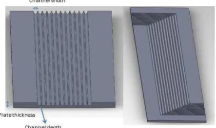
In this study, a simplified model of PCHE is selected as the computational domain, as depicted in Fig. 1. Some details of the geometrical configurations of the heat exchanger is tabulated in Table 1, the PCHE has 3 hot plates and 3 cold plates with a total of 12 straight channels in each plate. The channel pitch is 2.5 mm, channel width is 2 mm, and the channel depth is 1mm. The size of the plate is 272×55×1.65 mm3 as depicted in Fig. 2. The arrangement of the plates from the bottom to top is cold plate and followed by hot plate, cold plate, and so on. The numbering of the cold plate form the bottom to the top are PC1, PC2, PC3, and the numbering of the hot plate form the bottom to the top are PH1, PH2, and PH3, respectively as shown in Fig 2.
Figure 1. Schematic of cold and hot channel Plates
Three- Dimensional Simulation
The simulation is carried out using Flow simulation in Solidworks 2011. The simulation is performed with conjugate heat transfer between solid materials and fluids material. The material is alloy-617 and the temperature dependent properties along with air are implemented in the simulation. A total of three cases are made, and is denoted as follows:
Case1: cold channel 5 m/s, 200 °C hot channel 5 m/s, 700 °C Case2: cold channel 10 m/s, 200 °C hot channel 5 m/s, 700 °C Case3: cold channel 1 m/s, 200 °C hot channel 5 m/s, 700 °C
The temperature effectiveness of the heat exchanger İ can be determined by: ɂ ൌ ሺܶെ ܶೠሻȀሺܶ െ ܶሻ [1]
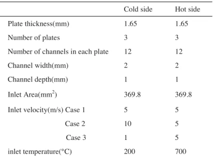
TABLE I. Detailed geometric parameters of PCHE
Cold side Hot side Plate thickness(mm) 1.65 1.65
Number of plates 3 3
Number of channels in each plate 12 12
Channel width(mm) 2 2
Channel depth(mm) 1 1
Inlet Area(mm2) 369.8 369.8
Inlet velocity(m/s) Case 1 5 5
Case 2 10 5
Case 3 1 5 inlet temperature(°C) 200 700
Result and Discussion
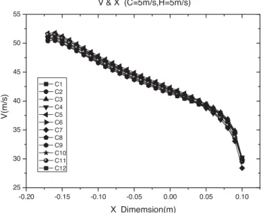
Three initial test cases were conducted to check the velocity distribution in every channel and the pressure drop in every plate as shown in Figs. 3, 4 and tables II, III, IV, V. For Case1, the velocity at the inlet experiences a sharp rise and followed by a steadily increase. The sharp rise of velocity is associated with the considerable rise of temperature which leads to a gigantic increase. The sharp rise of velocity is also related to the entrance effect where significant heat transfer performance in this region is encountered. It is also interesting to note that there are no significant departures of velocity amid different cold channels, indicating less mal-distribution within the channels. This is because associated with its comparatively high velocity. In practice, higher velocity gives rise to better flow distribution. Analogous results are also observed in Fig. 4 for Case2.
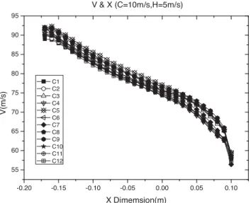
Further examining Fig. 3 and Fig. 4, it is found that the velocity distribution for all the channels has a turning point at 0.05 m (X) in both cases 1 & 2. The velocity distribution for all the channels is approaching in Case 1 at 0.05 m, whereas it is divided into two zones in case 2.
From, Table II one can notice that the effectiveness in Case 1 is higher as compared to Case 2 and Case 3. When the inlet velocity in cold channel is increased, the effectiveness is also increased, but the inlet velocity is set to 10 m/s, the effectiveness is decreased. Generally when the inlet velocity is increased, the maximum value velocity in channel is increased.
By looking to the results shown in Table III, IV, V, it appears that as when velocity in cold channel is increased, the corresponding pressure drop is also increased in cold channel, but it is decreased in hot channel. The results are associated with better heat transfer performance in the cold channel that brings down the effective temperature at the hot channel, thereby resulting in a lower pressure drop in the hot channel.
TABLE III. Pressure drop and Temperature in Case1
PC1 PC2 PC3 PH1 PH2 PH3
ǻP(Pa) ǻT(°C) ǻP(Pa) ǻT(°C) ǻP(Pa) ǻT(°C) ǻP(Pa) ǻT(°C) ǻP(Pa) ǻT(°C) ǻP(Pa) ǻT(°C)
Av 4572 162 4581 164 4519 159 1767 343 1780 388 1783 356
Figure 3. Velocity in in cold plate 2 channel with case 1 -0.20 -0.15 -0.10 -0.05 0.00 0.05 0.10 25 30 35 40 45 50 55 V & X (C=5m/s,H=5m/s) V( m /s) X Dimemsion(m) C1 C2 C3 C4 C5 C6 C7 C8 C9 C10 C11 C12
TABLE II. ǻT and effectiveness.
Case 1 Case 2 Case 3
ǻT(°C) 161 69 287
ǻT(°C) 360 352 168
Figure 4. Velocity in cold plate 2 channel with case 2
TABLE IV. Pressure drop and Temperature in Case 2
PC1 PC2 PC3 PH1 PH2 PH3
ǻP(Pa) ǻT(°C) ǻP(Pa) ǻT(°C) ǻP(Pa) ǻT(°C) ǻP(Pa) ǻT(°C) ǻP(Pa) ǻT(°C) ǻP(Pa) ǻT(°C)
Av 8434 67 8466 71 8276 69 1492 362 1252 318 1502 378
TABLE V. Pressure drop and Temperature in Case3
PC1 PC2 PC3 PH1 PH2 PH3
ǻP(Pa) ǻT(°C) ǻP(Pa) ǻT(°C) ǻP(Pa) ǻT(°C) ǻP(Pa) ǻT(°C) ǻP(Pa) ǻT(°C) ǻP(Pa) ǻT(°C)
Av 4572 162 4581 164 4519 159 1767 343 1780 388 1783 356
Conclusions
This study conducts a numerical simulation of PCHE operated at high temperature. The velocity distributions in PCHE channel, pressure drop and effectiveness with different inlet velocity in PCHE channel are reported. A total of three cases of printed circuit heat exchangers subjected to change of cold channel inlet velocity are reported. Based on the discussions, the following conclusions are made:
1. The effect of velocity distribution on the high temperature heat exchanger is quite significant. It is found that inlet velocity on the cold channel may affect the effectiveness. A sharp rise of velocity is encountered at the entrance region and only less flow distribution is observed. This is associated with the entrance effect and high velocity inlet.
2. For a fixed flowrate at the hot channel, it is found that raising the velocity in cold channel would result in the increase of pressure drop in the cold channel but the corresponding pressure drop in the hot channel is decreased. This is because better heat transfer performance in the cold channel brings down the effective temperature of hot channel and result in a lower pressure drop.
-0.20 -0.15 -0.10 -0.05 0.00 0.05 0.10 55 60 65 70 75 80 85 90 95 V & X (C=10m/s,H=5m/s) V(m /s ) X Dimemsion(m) C1 C2 C3 C4 C5 C6 C7 C8 C9 C10 C11 C12
Acknowledgments
The authors would like to express gratitude for supporting funding from the National Science Council of Taiwan (102-3113-P-009 -001).
References
1. K. Nikitin, Y. Kato and L. Ngo, Int. J. Refrigeration., 29, 807 (2006).
2. H. Zhang, L. Wang, S. Wang and M. Su, J. Power Sources, 183, 282 (2008). 3. J. K. Min, J. H. Jeong, M. Y. Ha and K. S. Kim, Heat Mass Transfer, 46, 175
(2008).
4. G. Kuchi, V. Ponyavin and Y. Chen, Int. J. Hydrogen Energy, 33, 5460(2008). 5. K. N. Song, S. D. Hong, H. Y. Lee and H. Y. Park, Procedia Engineering, 10, 48
(2011).
6. J. Schmidt, M. Scheiffele, M. Crippa, P. F. Peterson, E. Urquiza, K. Sridharan, L. C. Olson, M. H. Anderson, T. R. Allen, and Y. Chen, Int. J. Applied Ceramic
Technology, 8,1(2010).
7. F. Pra, P. Tochon, C. Mauget, J. Fokkens, S. Willemsen, Nuclear Engineering
and Design, 11, 3160 (2008).
8. K. A. Al-attab and Z. A. Zainal, Renewable Energy, 35, 913(2010).
9. M. Peksen, R. Peters, L.Blum, D. Stolten, Int. J. Hydrogen Energy, 36, 6851 (2011).