國立交通大學
應用化學研究所
博士論文
多層化結構高分子薄膜之製備與特性分析之研究
A Study on Preparation and Characteristics of
Laminar Polymeric Film
研究生:黃啟賢
指導教授:吳建興 教授
共同指導教授:黃俊欽 教授
i
Abstract (in English)
Laminar polymeric films are usually fabricated by coextrusion and blending processes. In a coextrusion process, a laminar polymeric film is formed into multilayer and parallel structures. In a blending process, on the other hand, the laminar polymeric film formed has laminar morphology of dispersed phases in its blend film. Because of the wide range of applications of laminar polymeric films as packaging materials, studies of the processes for forming, and the characteristics of, laminar polymeric films have become increasingly important. In this study, the aims are to predict the properties of the multilayer film and investigate the effect of adhesive on the laminar polymeric film.
In Chapters 2 and 3, we successfully fabricated three-layer (A/B/C) films, comprising high-density polyethylene (HDPE), tie layer [high-density polyethylene-grafted maleic anhydride (HDPE-g-MAH]], and polyamide-6 (PA-6), by a coextrusion blown-film process. The tensile behavior of the three-layer film can also be predicted from its component layers by using an additive rule and an empirical
constitutive equation — m T T T K • ⋅ ⎟ ⎠ ⎞ ⎜ ⎝ ⎛ ⋅ ⋅ = γ ε ε σ ε 2 2
exp , where σT, εT, and T
•
ε
are the true stress, the true strain, and the true strain rate, respectively, K and γε are constants,and m is the strain rate sensitivity — and a simplified constitutive equation — )
exp(
0 T
T σ γ ε
σ = ⋅ , where εT, σ0, and γ are the true strain, true yield stress and
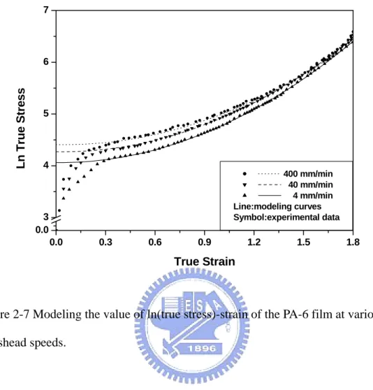
the strain hardening parameter, respectively — over the range of plastic deformation. There exists a good agreement between the experimental and predicted data at low crosshead speeds, but there is a relatively large discrepancy between them at high speeds, for both constitutive equations, because of the heat generated during
deformation. The valid strain range for the latter is smaller, however, than that for the former. On the other hand, the series model was examined to predict permeability of HDPE/tie/PA-6 three-layer film; there exists a good agreement between experimental data and this model for predicting both gas and water vapor permeabilities of three-layer films containing various volume fractions of PA-6.
Conventionally, one or more tie layers are used in coextrusion processes, e.g., in the preparation of HDPE/tie/PA-6 mentioned above, but having additional tie layers in a coextruded film makes the fabrication process more complex and expensive. To eliminate the need for tie layer(s) and to reduce the number of layers, we have also successfully fabricated three-layer (A/B/A) films, comprising a varying content of ethylene–vinyl alcohol copolymer (EVOH) as the internal layer and blends of low-density polyethylene (LDPE) and adhesive [low-density ethylene grafted with maleic anhydride (LDPE-g-MAH]] as the external layers, by a coextrusion blown-film process. In Chapter 4 ,we describe our investigation of the mechanical properties and compare their oxygen and water vapor permeabilities to a series model reflecting the content of adhesive. The peel strength increased sharply at LDPE-g-MAH content > 12.5 wt%; we associate this increase with a promotion of adhesion between layers that arises from the formation of ester bonds, as determined by FTIR spectroscopy, between EVOH and LDPE-g-MAH. The tensile strength did not change significantly upon increasing the LDPE-g-MAH content, but it had a small effect on elongation and modulus in both the machine and transverse directions. Tear strength decreased continuously, in both directions, upon increasing the LDPE-g-MAH content. The oxygen permeabilities of the three-layer films remained almost constant upon varying the amount of LDPE-g-MAH and all followed the series model. The water vapor permeabilities of the three-layer films, however, were affected by the degree of hydrogen bonding, which we analyzed by FTIR
iii
spectroscopy, to result in a discrepancy between the experimental findings and the series model, especially when the EVOH content was increased.
An alternative process to fabricate laminar polymeric film is the blending process. In Chapter 5, we investigated the morphological, thermal, barrier, and mechanical properties of low-density polyethylene/ethylene–vinyl alcohol blend (LDPE/EVOH; 85/15 wt%) in highly and biaxially oriented blown films. We used linear low-density polyethylene-grafted maleic anhydride (LDPE-g-MAH) in various amounts as the compatibilizer for this immiscible system. Thermal analyses of the blend films indicated that their melting temperatures, crystallization temperatures, and heats of fusion remain almost constant upon varying the amount of compatibilizer. The addition of the compatibilizer did not adversely affect the inherent properties of the blends, especially their barrier properties, through constraint effects of the grafted EVOH (EVOH-g-LD). The heat of fusion of EVOH obtained during the first heating was much higher than that of the second as a result of the stress-induced crystallization that occurs during the blown-film process. Oxygen permeation measurements demonstated that the oxygen barrier properties of both highly and biaxially oriented blown films decrease upon increasing the amount of compatibilizer, although morphological analysis indicated that the blends exhibit better laminar dispersion of the EVOH phase in the LDPE. The increase in oxygen permeability results from the formation of microvoids at the interface between the two phases during the blown-film process. Mechanical measurements indicated that there exists an optimal amount of LDPE-g-MAH at which both the tensile and tear properties are maximized in both the machine and transverse directions.
Abstract (in Chinese)
多層化結構高分子薄膜是一種單一結構的薄膜產品,包含了兩種或
兩種以上的高分子,彼此之間形成多層化且平行的結構。高分子薄膜
通常用於包裝用途,例如食品包裝、葯品包裝及化妝品包裝,這些用
途的包裝膜特性需求通常不只一種,而單一材料所製備的高分子薄膜
又無法提供多樣化的性質。因此將兩種或兩種以上高分子結合成多層
化結構的薄膜產品就應運而生了。多層化結構高分子薄膜的製備方式
通常有兩種,一種為共擠押製備,另一種為混鍊製程,本研究將對這
兩種製程所製備的薄膜特性做分析研究。
由共擠押製程所製備具有多重性質的多層化結構高分子薄膜,其整
體性質的表現則是來自於各層性質的貢獻。本研究以 HDPE/tie/PA-6
為例,來驗證性質預估的方法,由各層的性質來預估任何不同厚度組
成三層薄膜的拉伸性質及氣體穿透速率,若這預估的方法有效,對於
在薄膜組成的設計與搭配上,將會是一個非常經濟及有效率的方法。
用 series model 來預估氣體穿透率(包含氮氣、氧氣、二氧化碳及水
蒸氣),與實驗值有非常好的吻合性。在拉伸性質方面,首先找到適
當的構成方程式來描述薄膜的拉伸行為,而構成方程式中用來描述三
層薄膜拉伸行為的各個參數,可經由各層參數及 additive rule 來進行
預估,從實驗值與預估值的比較結果來看,在低速的拉伸測試時,有
很好的吻性,但在高速拉伸時,由於黏滯熱(viscous dissipation)的
產生,導致了實驗值與預估值之間的不一致。
在一般的共擠押製程中,由於黏著層的層數佔將近一半的層數,如
五層薄膜 LDPE/tie/EVOH/tie/LDPE,而黏著層的主要功能為界面黏
著,對整體的性質表現無實值的貢獻,因此在本研究中,將黏著層的
v
塑料混鍊至 LDPE 塑料中而當成混鍊層(blend layer)
,如此不僅可
增加 LDPE 與 EVOH 的接著性,並藉此將原有的五層減少為三層薄膜,
而形成 blend/EVOH/blend 的三層高分子薄膜,如此也可降低共擠押
模具的設計成本,簡化製程上的操作。在固定混鍊層與 EVOH 的厚度
比例下,界面黏著力,隨著黏著塑料在 LDPE 中含量的增加,黏著力
愈強,由 FTIR 的分析圖來看,這是由於黏著劑的馬來酸酐與 EVOH 的
氫氧基反應形成化學鍵-酯基(ester band)所造成的結果。而在拉
伸強度的表現上,黏著塑料含量的改變並沒有造成明顯的變化,在撕
裂強度,卻隨著黏著劑含量的增加,而明顯的下降。在氧氣穿透率方
面,在固定黏著劑的含量下,改變混鍊層與 EVOH 的厚度比例,氧氣
穿透率有很明顯的下降。而在水蒸氣穿透率方面,則是呈現持平,而
並沒有如預期般的上升,這是由於在 EVOH 中氫鍵的產生,由 FTIR 中
可知,隨著 EVOH 的增加,氫鍵的逐漸的增強,因此造成水分子不易
穿透,因此呈現持平的結果。
另外在本研究中,欲利用另一種製程,製備具有多層化形態的高分子
薄膜,使這單一薄膜同時具有各成份的特性,此種製程為混鍊製程。
欲混鍊的材料為高阻氧性的材料-EVOH、高阻水氣材料-LDPE 以及相
容劑-LDPE-g-MAH,經由單螺桿塑化後進入吹袋模具,而製備成薄膜。
由 SEM 圖來看,隨著相容劑含量的增加,分散相 EVOH 的長度逐漸的
變短,但層化的數目也愈多。另外由 OM 圖來看,分散相 EVOH 的形狀
則是逐漸由類似長條纖維狀而變成小顆粒的圓球狀。由 DSC 的分析圖
得知,在第一次升溫掃描時所求得的熔化熱比第二次高了許多,這是
由 於 在 製 備 薄 膜 的 程 中 造 成 了 順 向 結 晶 ( stress-induced
crystallization)所造成。在氧氣阻隔性方面並不如預期般的有明
顯的下降,這是由於在製備薄膜的過程中,因為高度的雙延伸,造成
分散相與連續相之間產生微微孔洞(microvoid)所導致的結果。在
拉伸性質方面,縱向(MD)的拉伸強度在相容劑為 1phr 時,有一極
大值,這是由於此時較為剛性的 EVOH 的形狀呈現長條狀,因此具有
纖繀強化(fiber-reinforcement)的作用,隨著相容劑的增加,EVOH
的形狀呈現圓球會,此作用便消失,再加上兩相的界面產生了微孔
洞,因此強度便下降。在 TD(縱向)的拉伸強度,應會隨著相容劑
的增加而逐漸的增加,但是在高含量的時候,卻呈現持平的趨勢,這
是由於微小孔洞將強度有所抵消所致。
vii
Acknowledge
誌謝
漫長的求學生涯終於畫下句點了,回顧過去的求學時光,許許多多
的回憶便湧上了心頭,其中的酸甜苦辣便成為此生中最寶貴的經驗。
首先感謝啟蒙恩師吳建興教授的引領,讓我進入了高分子加工這個
實用性相當高的領域。再來感謝高雄應用科技大學黃俊欽研發長在實
驗上的全力協助,讓學生能順利的完成研究內容,而黃研發長的專業
知識及工作效率更是學生值得學習的典範。
感謝廖士興、陳成寶、戴郡良、錢峰明、陳志倫、李曄旭、朱明毅
等諸位學長,讓我度過了剛進研究所生活的不適應期。再來感謝同學
尤均文及歷屆學弟妹在研究上及生活上的幫忙,尤其是陳勇志學弟,
是我在研究過程中的最佳幫手。
最後謹以此論文獻給我最親愛的家人,尤其是父母親無怨無悔的支
持,才能讓我毫無後顧之憂下,順利的取得博士學位。
感謝一同走過這段歲月與支持我的所有朋友。
Contents
Abstract (in English)
……….………….…………iAbstract (in Chinese)
………ivAcknowledge
………...viiContents
……….…………..…viiiList of Tables
……….………...………xiList of Figures
……….……….…...xiiChapter 1 Introduction
1.1 Laminar Polymeric Film
……….1-11.2 Coextrusion Process
……… 1-21.3 Blending Process
………...1-111.4 Objectives
………..1-151.5 References
……….1-17Chapter 2 Tensile Behavior of HDPE, PA-6 and HDPE/tie/PA-6
three-layer Films
2.1 Introduction
………..2-12.2 Experimental
………2-32.3 Constitutive Equation for Plastic Deformation
………...2-52.4 Results and Discussion
……….….2-82.5 Conclusions
……….2-13ix
Chapter 3 Predicting the Permeability and Tensile Behavior
of HDPE/tie/PA-6 Three-layer Films
3.1 Introduction
……….………….…………..….3-13.2 Experimental
……….…………..…3-33.3 Results and Discussion
……….………....3-63.4 Conclusions
……….…...3-103.5 References
……….….3-11Chapter 4 Adhesion, Permeability and Mechanical Properties of
Multilayered Blown Films using Maleated Low-Density
Polyethylene Blends as Adhesion-Promoting Layers
4.1 Introduction
……….………..….…….….4-14.2 Experimental
………...……….…4-34.3 Results and Discussion
……….…..…….…..4-74.4 Conclusions
……….….……...4-115.5 References
……….….…….4-11Chapter 5 Morphological, Thermal, Barrier and Mechanical
Properties of LDPE/EVOH Blends in Extruded
Blown Films
5.1 Introduction
……….…….………….….….….5-15.2 Experimental
……….……….…….….…5-35.3 Results and Discussion
……….…….……....5-55.4 Conclusions
……….……..…..5-10Chapter 6 Conclusions and Future Works
……….……….6-1List of Publications
……….……..………...6-4xi
List of Tables
Table 1-1 Materials combinations, special properties and important
applications of coextruded blown films………..1-22 Table 2-1 Thickness and volume fraction of the PA-6 layer in each
three-layer film………2-16 Table 2-2 The parameters K, γε, and m of the constitutive equation for the
HDPE, PA-6, and three-layer films recorded at various crosshead
speeds………..2-17 Table 2-3 True strain rates T
•
ε of the HDPE, PA-6, and three-layer films
recorded at various crosshead speeds………..2-18 Table 3-1 Thickness and volume fraction of PA-6 layer in three-layer films……3-14 Table 3-2 Gas Permeabilities of monolayer PA-6, monolayer HDPE and
three-layer films………..3-15 Table 3-3 Water Vapor Permeabilities of monolayer PA-6, monolayer
HDPE and three-layer films………3-16 Table 3-4 True yield stress (σ0) and strain hardening parameter (γ)of
HDPE, PA-6 and three-layer films at various crosshead speeds……….3-17 Table 4-1 Thickness of Individual Layers of Three-layer Films with various
EVOH contents………...4-14 Table 4-2 Properties of films for Individual Component Materials………...4-15 Table 4-3 IR absorbance of hydroxyl and ester bands of three-layer films with
different LDPE-g-MAH contents………4-16 Table 5-1 Tensile properties of pure LDPE and EVOH films for both MD
List of Figures
Figure 1-1 Multilayer laminar structure by coextrusion process………...1-23 Figure 1-2 Coextrusion blown film line. (1) Extruders; (2) die and
cooling equipment; (3) sizing unit; (4) thickness gauge;
(5) take-off unit; (6) film edge control; (7) winder……….1-23 Figure 1-3 A three-layer multimanifold spiral mandrel blown film die………...1-24 Figure 1-4 A Stackable blown film die……….1-24 Figure 1-5 Coextrusion flat film line. (1) Extruders; (2) die; (3) casting section;
(4) winder………1-25 Figure 1-6 Cross-sectional view of three-layer multimanifold flat film die……1-25 Figure 1-7 A feedblock/single manifold die……….1-26 Figure 1-8 The principle of the feedblock for coextruding multilayer film.
Numbaer of layers is equal to number of feedports………1-26 Figure 1-9 Combination feedblock and multimanifold die system. Feedblock
feeds center-die manifold………1-27 Figure 1-10 Interlayer instability……….1-27 Figure 1-11 Interlayer instability pattern. (a) zig-zag; (b) wave………..1-28 Figure 1-12 Viscous encapsulation in coextrusion flat-die………..1-28 Figure 1-13 Progression of a two-layer polystyrene structure as it flows down
a square channel. Cuts at axial distances from the entry (a) 5; (b) 20; (c) 30; (d) 40; (e) 50; (f) 58 cm……….1-29 Figure 1-14 Multilayer laminar structure by blending process. (a) top view;
xiii
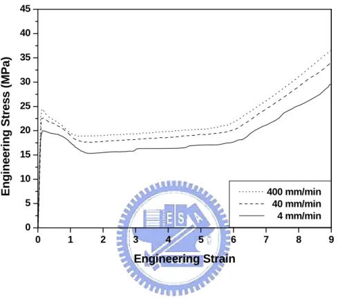
Figure 2-1 Engineering stress–strain curves of the HDPE film recorded at
various crosshead speeds……….2-19 Figure 2-2 True stress–strain curves of the HDPE film recorded at various
crosshead speeds………..2-20 Figure 2-3 Modeling the value of ln(true stress)-strain of the HDPE film
at various crosshead speeds……….2-21 Figure 2-4 Comparison between the modeling curves and the experimental
true stress–strain data for the HDPE film recorded at various
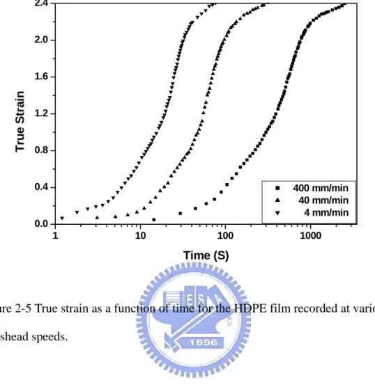
crosshead speeds………..2-22 Figure 2-5 True strain as a function of time for the HDPE film recorded
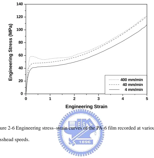
at various crosshead speeds………..2-23 Figure 2-6 Engineering stress–strain curves of the PA-6 film recorded at
various crosshead speeds……….2-24 Figure 2-7 Modeling the value of ln(true stress)-strain of the PA-6 film
at various crosshead speeds……….2-25 Figure 2-8 Comparison between the modeling curves and the experimental
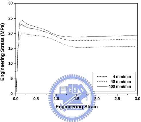
true stress–strain data for the PA-6 film………...2-26 Figure 2-9 Engineering stress–strain curves of the three-layer films, having
various volume fractions of PA-6, recorded at a crosshead speed
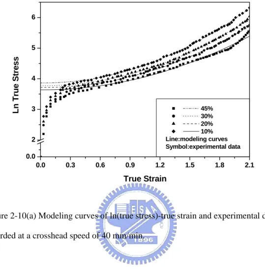
of 40 mm/min………...2-27 Figure 2-10(a) Modeling curves of ln(true stress)-true strain and experimental
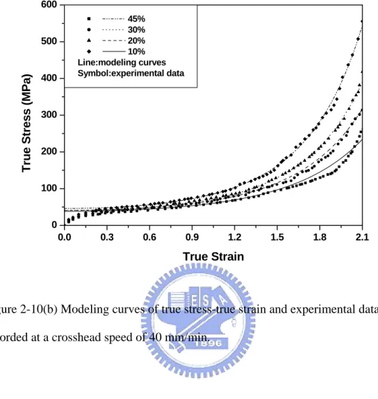
data recorded at a crosshead speed of 40 mm/min………...2-28 Figure 2-10(b) Modeling curves of true stress-true strain and experimental
data recorded at a crosshead speed of 40 mm/min………...2-39 Figure 2-11 Comparisons of the relationships between Equations (20)
Figure 2-12(a) Comparison between the values of K of the three-layer films, having various volume fractions of PA-6, determined using the additive rule and that from the experimental data
at crosshead speeds of 4 mm/min………2-31 Figure 2-12(b) Comparison between the values of K of the three-layer films,
having various volume fractions of PA-6, determined using the additive rule and that from the experimental data at crosshead
speeds of 40 mm/min………..2-32 Figure 2-12(c) Comparison between the values of K of the three-layer films,
having various volume fractions of PA-6, determined using the additive rule and that from the experimental data at crosshead
speeds of 400 mm/min………2-33 Figure 2-13(a) Comparison between the values of γε of the three-layer films,
having various volume fractions of PA-6, determined using the additive rule and that from the experimental data at crosshead
speeds of 4 mm/min……….2-34 Figure 2-13(b) Comparison between the values of γε of the three-layer films,
having various volume fractions of PA-6, determined using the additive rule and that from the experimental data at crosshead
speeds of 40 mm/min………...3-35 Figure 2-13(c) Comparison between the values of γε of the three-layer films,
having various volume fractions of PA-6, determined using the additive rule and that from the experimental data at crosshead
speeds 400 mm/min……….2-36 Figure 2-14(a) Comparison between the values of m of the three-layer films,
xv
additive rule and that from the experimental data at crosshead
speeds of 4 mm/min……….2-37 Figure 2-14(b) Comparison between the values of m of the three-layer films,
having various volume fractions of PA-6, determined using the additive rule and that from the experimental data at crosshead
speeds of 40 mm/min………...2-38 Figure 2-14(c) Comparison between the values of m of the three-layer films,
having various volume fractions of PA-6, determined using the additive rule and that from the experimental data at crosshead
speeds of 400 mm/min……….3-39 Figure 3-1 Nitrogen (N2) permeabilities of three-layer films with various
content of PA-6 layer………...3-18 Figure 3-2 Oxygen (O2) permeabilities of three-layer films with various
content of PA-6 layer………...3-19 Figure 3-3 Carbon dioxide (CO2) permeabilities of three-layer films with
various content of PA-6 layer………..3-20 Figure 3-4 Water vapor permeabilities of three-layer films with various
content of PA-6 layer………...3-21 Figure 3-5(a) Engineering stress-strain curves of HDPE film at various
crosshead speeds………..3-22 Figure 3-5(b) Engineering stress-strain curves of PA-6 films at various
crosshead speeds………..3-23 Figure 3-6(a) True stress-strain curves of HDPE films at various
crosshead speeds………..3-24 Figure 3-6(b) True stress-strain curves of PA-6 films at various
Figure 3-7(a) Modeling and experimental data of Ln true stress-strain of
HDPE films at various crosshead speeds……….3-26 Figure 3-7(b) Modeling and experimental data of Ln true stress-strain of
PA-6 films at various crosshead speeds………...3-27 Figure 3-8(a) Comparison of true stress-strain curves between modeling curves
and experimental data of HDPE films at various crosshead speeds…3-28 Figure 3-8(b) Comparison of true stress-strain curves between modeling curves
and experimental data of PA-6 films at various crosshead speeds…...3-29 Figure 3-9(a) Engineering stress-strain curves of three-layer films as a function
of volume fraction of PA-6 layer at crosshead speed 40 mm/min. Thick solid lines represent the component layer of PA-6 and
HDPE, respectively………..3-30 Figure 3-9(b) True stress-strain curves of three-layer films as a function of
volume fraction of PA-6 layer at crosshead speed 40 mm/min. Thick solid lines represent the component layer of PA-6 and
HDPE, respectively………..3-31 Figure 3-10 Modeling and experimental data of Ln true stress-strain of
three-layer films as a function of volume fraction of PA-6 layer
at crosshead speed 40 mm/min………3-32 Figure 3-11 Comparison of true stress-strain curves between modeling curves
and experimental data of three-layer films as a function of volume fraction of PA-6 layer at crosshead speed 40 mm/min………3-33 Figure 3-12(a) Comparison of strain hardening parameter between additive rule
and experimental data as a function of PA-6 content at crosshead
speed of 4 m/min………..3-34 Figure 3-12(b) Comparison of strain hardening parameter between additive rule
xvii
and experimental data as a function of PA-6 content at crosshead
speed of 40 mm/min……….3-35 Figure 3-12(c) Comparison of strain hardening parameter between additive rule
and experimental data as a function of PA-6 content at crosshead
speed of 400 mm/min………...3-36 Figure 3-13(a) Comparison of true yield stress between additive rule and
experimental data as a function of PA-6 content at crosshead speed of 4 mm/min……….3-37 Figure 3-13(b) Comparison of true yield stress between additive rule and
experimental data as a function of PA-6 content at crosshead speed of 40 mm/min………...3-38 Figure 3-13(c) Comparison of true yield stress between additive rule and
experimental data as a function of PA-6 content at crosshead speed of 400 mm/min……….3-39
Figure 4-1 Peel Strength between LDPE/LDPE-g-MAH blend and EVOH of three-layer films as a function of LDPE-g-MAH content………4-17 Figure 4-2(a) IR absorption spectra of three-layer films at the hydroxyl band
with various LDPE-g-MAH contents……….…….4-18 Figure 4-2(b) IR absorption spectra of three-layer films at the ester band with
various LDPE-g-MAH contents………..4-19 Figure 4-3(a) Strength at break of three-layer films as a function of
LDPE-g-MAH content for both MD and TD………...4-20 Figure 4-3(b) Elongation at break of three-layer films as a function of
LDPE-g-MAH content for both MD and TD………...4-21 Figure 4-3(c) Modulus of three-layer films as a function of LDPE-g-MAH
content for both MD and TD………4-22 Figure 4-4 Tear strength of three-layer films as a function LDPE-g-MAH
content for both MD and TD………4-23 Figure 4-5 Oxygen permeabilities of three-layer films as a function of
LDPE-g-MAH content……….………4-24 Figure 4-6 Oxygen permeability of three-layer films as a function of
EVOH content……….……….4-25 Figure 4-7 Water vapor permeability of three-layer films as a function of
LDPE-g-MAH content……….…....4-26 Figure 4-8 Water vapor permeability of three-layer films as a function of
EVOH content……….……….4-27 Figure 4-9 IR absorption spectra of three-layer films at the hydroxyl band
with various EVOH contents……….………..4-28 Figure 5-1 SEM micrographs of LDPE/EVOH blend films with various
compatibilizer contents; (a) 0 phr, (b) 1 phr, (c) 4 phr and
(d) 8 phr………...5-15 Figure 5-2 Optical micrographs of LDPE/EVOH blend films with various
compatibilizer contents; (a) 0 phr, (b) 0.5 phr, (c) 1 phr, (d) 6 phr
and (e) 10phr………5-16 Figure 5-3(a) The DSC 1st heating thermograms of LDPE/EVOH blend films
with various compatibilizer contents………...5-17 Figure 5-3(b) The melting peak temperature of LDPE/EVOH blend films with
various compatibilizer in DSC 1st heating thermograms……….5-18 Figure 5-3(c) The heat of fusion of LDPE/EVOH blend films with various
compatibilizer in DSC 1st heating thermograms………..5-19 Figure 5-4(a) The DSC 2nd heating thermograms of LDPE/EVOH blend films
xix
with various compatibilizer contents………...5-20 Figure 5-4(b) The melting peak temperature of LDPE/EVOH blend films with
various compatibilizer in DSC 2nd heating thermograms………5-21 Figure 5-4(c) The heat of fusion of LDPE/EVOH blend films with various
compatibilizer in DSC 2nd heating thermograms……….5-22 Figure 5-5 Melting peak temperatures of 1st and 2nd heating of LDPE/EVOH
blend films with various compatibilizer contents………5-23 Figure 5-6 Heat of fusions of 1st and 2nd heating of LDPE/EVOH blend films
with various compatibilizer contents………...5-24 Figure 5-7(a) The DSC cooling thermograms of LDPE/EVOH blend films with
various compatibilizer contents (cooling rate = 2℃/min)…………...5-25 Figure 5-7(b) The crystallization peak temperature (Tc) of LDPE/EVOH blend
films with various compatibilizer contents (cooling rate = 2℃/min) in the DSC cooling thermograms……….5-26 Figure 5-8 Oxygen permeability of LDPE/EVOH blend films with various
compatibilizer contents. Dash line represents the oxygen
permeability of LDPE………..5-27 Figure 5-9 Tensile strength at break of LDPE/EVOH blend films with
various compatibilizer contents for both MD (machine direction) and TD (transverse direction)………..5-28 Figure 5-10 Elongation at break of LDPE/EVOH blend films with various
compatibilizer contents for both MD (machine direction) and TD
(transverse direction)……….……...5-29 Figure 5-11 Tear propagation resistance of LDPE/EVOH blend films with
various compatibilizer contents for both MD (machine direction) and TD (transverse direction)………..5-30
Chapter 1
Introduction
1.1 Laminar Polymeric Films
Polymeric films comprise one of the most important types of products created in the polymer industry. A large percentage of these films are used in the packaging industry. A very wide range of criteria must be applied when considering the type of film to be used for a particular purpose. In general, however, these criteria fall into three broad groups. The first group is basically concerned with the strength of the films, such as their tensile, impact, and tear strengths and their stiffnesses. The second group of properties may be classed broadly as the films’ transmission properties, which include their permeabilities toward gases, vapors, and odors. Light transmission is also included here; it covers properties such as the “see-through” clarity and haze. For convenience, other optical properties, such as a film’s gloss, also are dealt with in this section. These first two groups deal with those properties that are important to the final end-use performance. The third and final group includes the properties that are more concerned with the performance of the films during the converting and packaging processes; these properties include the film’s coefficient of friction, blocking, heat sealability, and crease-of-flex resistance [1].
One of the most important requirements for the use of plastics as packaging films is their impermeability to gases and hydrocarbons. Their mechanical properties should also meet product specifications. In most cases, one polymeric material cannot offer
1-2
all of the properties required; therefore, a combination of polymers is employed to produce polymeric films that have laminar structures.Usually, the laminar polymeric film is prepared by either a coextrusion or blending process; the details of the two processes are described in the following sections.
To explain the versatility of laminar polymer films, it is convenient to provide an example here. Polyethylene is an excellent moisture barrier for packaging and its low cost, strength, and ease of processing make it suitable for many applications. Its inability, however, to act as a barrier for oxygen, aromatics, and oils limits its potential applications. On the other hand, ethylene–vinyl alcohol copolymer (EVOH) possesses excellent barrier properties toward oxygen, aromatics, and oils [2–5]. Unfortunately, EVOH is highly sensitive to moisture, which alters its ability to act as an oxygen barrier [6,7]. A laminar film processed from these two films through a coextrusion or blending process would possess a combination of the advantageous properties of each material. The word “laminar”, which originates from studies of transport phenomena, describes a smooth, uniform, non-turbulent flow of a gas or liquid in two or more parallel layers, with little mixing between layers. For films possessing laminar structures, the term describes component polymers that are positioned in uniformly parallel arrangements with respect to one another without intermixing.
1.2 The Coextrusion Process
1.2.1 Introduction
Conventionally, polymeric films having laminar structures are fabricated by either a coextrusion or lamination process. The attractions of the coextrusion process lie on both economic and technical grounds. It is a single-step process that starts from two
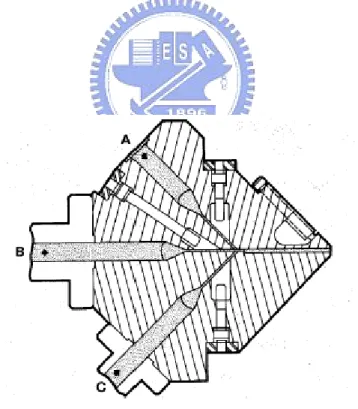
or more polymers that are simultaneously extruded and shaped in a single die to form a laminar polymeric film or sheet. The laminar polymeric films produced by the coextrusion process may also be called multilayer films. Figure 1-1 displays a typical laminar polymeric film fabricated by a coextrusion process; it comprises a functional layer, a bonding (or tie) layer, and a support layer [8]. The functional layers, ethylene-vinyl alcohol copolymer (EVOH) and Poly(vinylidene chloride) (PVDC), provides excellent oxygen barrier properties; the bonding layer is a thermoplastic, extrudable polymer that adheres to the otherwise incompatible polymers; the tasks of support layers in the coextrusion process are to achieve good mechanical strength, weldability, moisture barrier, transparency or colorability, and printability properties in the final laminar film, as well as to improve the conversion behavior. Each layer contributes different properties that improve the overall performance of the film. Table 1-1 lists the material combinations and special properties of important of coextruded blown films.
Coextrusion has developed into an important polymer fabrication process and it provides large growth opportunities for the polymer industry. The applications of coextruded multilayer polymers are challenging those of such traditional materials as metals, glasses, papers, and textiles. Coextrusion allows the ready manufacture of products having layers thinner than can be made and handled from their individual layers. Consequently only the necessary thickness of a high-performance polymer is required to meet the particular specifications of the product. Layers may be used, for example, to place colors, bury recyle, screen ultraviolet radiation, provide barrier properties, minimize die-face buildup, and to control the film’s surface properties. Additives, such as antiblock, antislip, and antistatic agents, can be placed in specific layer positions. High-melt-strength layers can carry low-melt-strength materials during fabrication. The largest market for coextruded films and sheets is the
1-4
packaging industry; for example, two- or three-layer films are used as trash bags and five-to-nine-layer structures as flexible and semi-rigid packages. As many polymers as are necessary may be used to obtain the desired heat sealibility, barrier properties, chemical resistance, toughness, formability, and aesthetic appearance. Growing markets for applications of the coextrusion process are in the automotive, construction, appliance, and photoelectronics industries, and in food and medical packaging.
The choice of whether to use the blown or flat film process normally depends on the desired rate and final properties of the structure. Flat-film lines can typically run at a higher rate than can blown-film lines because the cooling efficiency of a chill roll is higher than that of the air used to cool the bubble. The flat film process, however, produces a product having uniaxial orientation, rather than the biaxial orientation produced by the blown film process. In many cases, the biaxial orientation is preferred because it produces a film that has more-balanced physical properties. The biaxial orientation can be also achieved by using a tentering process, but it comes with a higher cost and requires complicated steps. In our studies, we prepared laminar polymeric films by coextrusion blown-film processes.
1.2.2 Methods of Coextruding Films
There are two fundamentally different methods for coextruding films, namely, the coextrusion blown-film and coextrusion flat-film processes. The capital and operating costs for a coextrusion blown film process and a flat-die, chill-roll casting process depend on the product mix and utilization. Equipment suppliers provide comparative economic evaluations for specific products. The extruder used before the die and the take-off equipment used afterwards are standard equipment applied to the single-layer film manufacture of both blown and flat films.
polymers that have been plasticized and homogenized in separated extruders, fed into a coextrusion blown-film die to form a tubular structure, blown into a bubble, cooled and passed through the collapse frame, and collected by a winder. Figure 1-2 depicts the setup of a coextrusion blown-film process. The design of coextrusion blown-film die used most commonly today is that of a multimanifold spiral mandrel (Figure 1-3). This die consists of several concentric manifolds, one located within another. The manifolds are supported and secured through the base of the die. Each manifold consists of a flow channel that spirals around the mandrel, which allows the melt polymer to flow down the channel or leak across a land area to the next channel. This flow pattern smoothes out the flow of the polymer and minimizes any weld lines in the final film. Another type of coextrusion blown film die is the stackable plate die (Figure 1-4). In this type of die, each layer is spread uniformly and formed into a tube in a single plate. The plates are then stacked on top of one another and the layers are added sequentially. This type of die is becoming popular for specific applications because the number of layers can be adjusted by simply changing the number of plates in the die. The major disadvantage for this type of die is that a large separating force exists between the plates and, thus, many die bolts are required to hold the plates together. This situation means that the plates must have rather large diameters to maintain structural integrity and this requirement can produce longer flow paths and temperature differentials that can be detrimental to thermally sensitive polymers.
The coextrusion flat-film process is based on the principle of shaping two or more polymers, which have been plasticized and homogenized in separated extruders, into a planar structure in a coextrusion flat die, cooling and stabilizing this structure by means of roll contact, and then winding it up to a trimmed working width. Figure 1-5 displays the setup of a coextrusion flat-film process. Two basic types of die used in flat-die coextrusion system are the multimanifold and feedblock/single-manifold dies.
1-6
A hybrid-type die combines feedblocks with a multimanifold die.
In a multimanifold die (Figure 1-6), each layer incorporates individual manifolds that extend to the full width of the die. Each manifold is designed to distribute its polymer layer uniformly before combining it with the other layers. The major advantage of a multimanifold die is the ability to coextrude polymers that have very different viscosities because each layer is spread independently prior to being combined. A significant disadvantage of wide multimanifold dies is the difficulty in coextruding very thin layers, such as thin cap or thin tie layers. When using a wide die, it is difficult to obtain uniformity when the extrusion rate per width is very low; additionally, it is expensive and requires the attention of skilled operators. The feedblock/single-manifold dies of a flat-die coextrusion system use a feedblock before a conventional single manifold (Figure 1-7). A layered melt stream, which is prearranged ahead of the die inlet by the feedblock, is extended to the width of the die as it is reduced in thickness (Figure 1-8). Polymer melts from each extruder can be subdivided into as many layers as desired in the final product. One limitation of the use of feedblocks is that polymer viscosities must be matched fairly closely because the combined melt stream must spread uniformly within the die. A severe viscosity mismatch results in lay nonuniformity; the lower viscosity material tends to flow to the die edges. A crude rule of thumb is that polymer viscosities must be matched to within a factor of three or four, which is a reasonably broad range for many commercially important coextrusion processes. Often, to avoid flow instabilities, polymers are intentionally selected that have mismatched viscosities. The layer nonuniformity expected to arise from the mismatch is compensated by varying the melt temperature, to eliminate the viscosity mismatch, or by using a feedport that has a shaped geometry. Combinations of feedblocks and a multimanifold die are also used commercially. The multimanifold die can incorporate the same design principles as
the feedblock: i.e., vanes separating individual manifolds within the die. In a sense, the multimanifold die is a wide feedblock. A feedblock may be attached to one or more manifold inlets, as indicated in Figure 1-9. With this system, it is possible to coextrude polymers that have widely different viscosities and processing temperatures.
1.2.3 Layer Nonuniformity in Coextrusion Processes
Polymer rheology information is critical for designing coextrusion dies and feedblocks. The flow characteristics of the polymer must be considered when selecting materials for coextruded products. The viscosities of non-Newtonian polymers depend on the extrusion temperature and shear rate, both of which are factors that may vary within the coextrusion die. The shear rate dependence is further complicated because it is determined by the position and thickness of a polymer layer in the melt stream. The die or feedblock that has the best design does not necessarily ensure a commercially acceptable product. Layered melt streams flowing through a coextrusion die can spread nonuniformly or can become unstable, which can lead to layer nonuniformities — and even intermixing of layers — under certain conditions. The causes of layer deformation are related to non-Newtonian flow properties of polymers and viscoelastic interactions. Previous studies have shown that variations in layer thicknesses during coextrusion processes can arise from many causes, with several of the primary ones being interlayer instability, viscous encapsulation, and elastic layer rearrangement.
1.2.3.1 Interlayer Instability
Interfacial instability is an unsteady-state process in which the interface location between layers varies locally in a transient manner. Interface distortion due to flow
1-8
instability can cause thickness nonuniformities in the individual layers while still maintaining a product that has constant thickness. These instabilities result in irregular interfaces — and even layer intermixing in severe cases. At very low flow rates, the interface is smooth, as indicated in Figure 1-10(a). At moderate output rates, low-amplitude waviness of the interface is observed [see Figure 1-10(b]]; this waviness is barely noticeable to the eye and may not interfere with the function of the multilayer film. At higher output rates, layer distortion becomes more severe [Figure 1-10(c]]. If a large-amplitude waveform develops in the flowing multilayer stream within the die, the velocity gradient can carry the crest forward and convert it into a fold. Multiple folding results in an extremely jumbled, intermixed interface. This type of instability, which commonly is called “zigzag instability”, has been observed in tubular blown-film, multimanifold, and feedblock/single manifold dies. This instability develops in the die land; its onset can be correlated with a critical interfacial shear stress for a particular polymer system [9]. The most important variables that influence this instability are the skin-layer viscosity, skin-to-core thickness ratio, total extrusion rate, and die gap. Although the interfacial shear stress does not cause instability, elasticity is related to shear stress; the interfacial stress is used to correlate variables for a particular system. Interfacial instability in a number of coextruded polymer systems has been correlated experimentally with their viscosity ratios and elasticity ratios [10], and a simplified rheology review is available [11]. Other studies have focused on viscosity differences [12–14], surface tension [15], critical stress levels [9,16,17], viscosity model parameters [18–20], and elasticity [21–29]. Other types of instabilities may exist: for example, a problem has been observed in the feedblock coextrusion of axisymmetric sheets [30]. A wavy interface is also characteristic of this instability, but the wave pattern is more regular when viewed from the surface. The instability, which commonly is called “wave instability”,
originates in the die, well ahead of the die land; the internal die geometry influences both the severity and the pattern. For a given die geometry, the severity of instability increases with structure asymmetry; some polymers are more susceptible to unstable flow than are others. It has been suggested that this type of instability may be related to the extensional rheological properties of the polymers used in the coextruded structure [31]. Figure 1-11 provides examples of both zigzag and wave instabilities. No complete predictive theory exists that explains these complicated rheological interactions, but the accumulated experience of polymer producers, equipment suppliers, and experienced fabricators provides guidance in polymer selection.
1.2.3.2 Viscous Encapsulation
The importance of viscosity matching for layer uniformity was first studied in the capillary flow of two polymers for bicomponent fibril production [32–35]. Two polymers, which are introduced side by side into a round tube, experience interfacial distortion during flow if the viscosities are mismatched. The lower-viscosity polymer migrates to regions of highest shear (at the wall) and tends to encapsulate the higher-viscosity polymer (Figure 1-12); it is possible for the lower-viscosity polymer to totally encapsulate the higher-viscosity polymer. Nature seeks the path of least resistance. The degree of interfacial distortion that is due to the viscosity mismatch depends on the extent of the difference in viscosity, the shear rate, and the residence time. Tubular blown-film dies are more tolerant of viscosity mismatch because the layers are arranged concentrically, i.e., there are no ends. Since streamlines cannot cross each other, further migration cannot occur, but good die design is required to obtain concentric layers.
1-10
While matching the viscosities of adjacent layers has proven to be a very important requirement, the effect of polymer viscoelasticity on layer thickness uniformity is also an important consideration in the coextrusion process [36–40]. It has been shown that, in a die that can distort the interface between layers, polymers that are comparatively high in elasticity produce secondary flows normal to the primary flow direction (Figure 1-13). This effect becomes more pronounced as the width of a flat die increases. Appropriate shaping of the die channels can minimize the effect of layer interface distortion that is due to elastic effects. Coextruding a structure that contains layers of polymers with alternating low and high levels of elasticity can cause interface distortion that is due to the differences in elasticity between the layers in the flat dies. Typically, this effect is not observed in tubular dies.
1.2.3.4 Solution Method for Layer Deformation Problem
Zigzag-type interfacial instability can be reduced or eliminated by increasing the skin-layer thickness, increasing the die gap, reducing the total rate, or decreasing the skin polymer viscosity; these methods may be used singly or in combination. These remedies reduce interfacial shear stress, and stable flow results when it is below the critical stress for the polymer system being coextruded. Most often, it is the skin layer polymer viscosity that is decreased. In feedblock coextrusion, the resultant viscosity mismatch imposed by this remedy can cause variations in layer thickness. Shaped skin layer feedslots are then typically used to compensate and produce a uniform product. A review of techniques used to minimize this type of layer deformation has been published [41]. Care should also be taken when designing the joining geometry in a feedblock or die. To minimize instabilities, the layers should have similar velocities at the merging point. The joining of the layers should occur in a geometry that is as parallel as is realistically possible, rather than joining them in a
perpendicular manner. The layers should also merge into a channel that is of an appropriate height so that it does not force one layer to flow into the other. Wave instability is related to the extensional viscosities of the individual layers. This finding implies that all of the design criteria mentioned previously for layer joining are also important for this type of instability, as is the spreading of the layers in a film or sheet die. Since this type of instability is related to extensional viscosity, the rate at which the layers are stretched in the die will affect the forces in each layer. In structures containing materials that have high extensional viscosities, the die should be designed to spread the layers slowly and at a uniform rate; this process will help minimize wave pattern instabilities.
1.3 Blending Process
1.3.1 Introduction
The coextrusion process does have some disadvantages, such as the high cost of investing in equipment and the difficulty in process control resulting from requirements for multiple extruder and dies, adhesives between layers, and multi-step operations. In addition, multilayer composite films have limitations in their recyclability because the resins, which have different characteristics, adhere together. Recently, diverse techniques have been proposed to produce laminar structures for preparing food packaging films, such as sol-gel silica coating[42,43], plasma coating [44], and blending [45,46]. Among these techniques, the blending approach for improving barrier properties has been recognized as an attractive methodology because existing extrusion processing systems can be used without further investment of equipment. Blending is a process that combines two or more polymers into a polymer blend through mixing. Such a blend is sometimes called an “in situ”
1-12
composite because of the shaping that occurs in situ during processing. This blend system acts as a dispersion of one polymer within the other, with chemical linking occurring between dissimilar chains across the interface. In packaging applications, a combination of a barrier material (EVOH) and a lower-cost matrix material (PE or PP) is fabricated into the polymeric film. Figure 1-14 displays the laminar structure of a blend film comprising LDPE as the matrix and EVOH as the dispersed phase.
1.3.2 Factors that Affect Laminar Morphology
Many properties, such as permeability and mechanical properties, are determined by the morphology of the blend film. Generally, the morphology is determined by many factors, such as the rheological properties of the component polymers, the interfacial tension, the blend composition, and the processing type and its parameters. Significant melt-processing parameters include the flow patterns, the shear stresses, the mixing history, and the processing temperatures. It has been established that a high shear rate, a viscosity ratio (viscosity of dispersed phase/viscosity of matrix) smaller than, or close to, unity [45,47,48], and a low interfacial tension are all favorable for increasing the level of deformation and breakup of the dispersed-phase droplets [49–51]. It is well established that extensional flow is more efficient than shear flow in the deformation of the dispersed phase [52–55]. One of the most important factors for controlling the blend morphology is modifying the interface between the phases by adding a compatibilizer to obtain greater compatibility. Improved compatibility ensures an efficient stress transfer from the continuous phase to the dispersed phase during the extrusion and stretching process and, consequently, it results in greater deformation of the dispersed phase [56]. Thus, the addition of a compatibilizer improves the dispersion and, in some cases, enhances the ultimate mechanical properties of the blends [57–61]. Usually, there is an optimum content of
compatibilizer required to improve the properties [62–64].
1.3.3 Relation of Laminar Morphology and Properties
In polymer blend system, improving the barrier properties is achieved through the formation of a laminar morphology of the dispersed-phase, barrier material having a moderate aspect ratio. This situation arises because of the orientation effect, which occurs during the extrusion process, that results in an increase of tortuous paths [45,47,62,65–67]. Alternatively, the improvement in mechanical properties is achieved through the formation of a laminar morphology of the dispersed-phase, reinforced material having a high aspect ratio, such as a fibril-reinforced polymer blend [68–70]. The orientation of the dispersed phase in the form of fibrils, which is directly related to the stiffness of the phase, has been identified as the key parameter for determining the mechanical performance of the entire in situ composite [71].
The first successful attempt to produce a blow-molded high-barrier container with developed laminar morphology was reported by Subramanian [72]. The results showed that PA-6, the barrier resin, could be distributed in the form of large, thin sheets, which have laminar structure, in the HDPE matrix by extruding the blends under special extrusion conditions. In addition, a PP/EVOH blend film that has higher barrier properties was obtained by generating a laminar structure having a larger area by using a biaxial orientation film process [62]. Although EVOH exhibits excellent gas barrier properties and transparency, it has some drawbacks, such as its high cost, low toughness, and difficulty to process [73]. On the other hand, PA is inexpensive relative to EVOH and exhibits both high resistance to the permeation of hydrocarbons and good toughness. [74]. Thus, polypropylene and polyamide can be blended to improve the thermal and mechanical properties of polypropylenes. Furthermore, the addition of polyamide to polypropylene results in an improvement in the barrier
1-14
properties. Polypropylene exhibits excellent barrier properties to moisture, but it is a poor barrier toward O2, CO2, and N2. In contrast, polyamide possesses high barrier
properties toward these gasses and a high resistance toward hydrocarbons [75]. A compatibilizer must be used, however, to enhance the interphase adhesion and phase stability in immiscible blends of PP and PA [76]. The ultimate barrier property of the polymer blend depends on the morphological structure of the dispersed phase, the intrinsic barrier property of each component, and the nature of the interface between the two phases [66,77,78]. Recently, it was reported that injection-molded PP/PA blends having improved barrier properties can be produced by generating a laminar morphology of a polyamide-dispersed phase that was induced by shear and elongational flows [79]. Following the principles mentioned above, Kamal and co-workers [80,81] prepared PP/EVOH blends, which have laminar morphology, under controlled processing conditions using a special die designed to incorporate converging and diverging sections. In the process of producing this film, however, the authors did not obtain a blend film with highly improved barrier properties because drawing occurred only in the machine direction during the take-off stage from the die to the chilled roll, and it resulted in a laminar film of the dispersed phase having a small area. Faisant et al. have also reported that the oxygen permeability of PP/EVOH blends can be decreased significantly by inducing fibrillar and laminar morphologies of the EVOH phase by operating only under uniaxial drawing between the two roll mills. In the processing aspect, the final blend morphology is also determined by an orientation operation [46]. Yeo et al. has reported that an improved barrier property can be obtained by generating a laminar structure of the dispersed phase in the matrix phase of a PP/EVOH blend by applying a biaxially oriented film process [62]. This laminar morphology, which is induced by biaxial orientation, results in a significant increase in the oxygen barrier properties of PP/EVOH (85/15) blends: by ca. 10 times
relative to that of pure PP. Lee and Kim proposed a indicator, (L × R) × N, of the oxygen barrier properties, where L × R is the average dimension of the dispersed phase and N is the average number of dispersed phase layers per µm. An optimum value of this indicator, which improves the barrier properties, was obtained upon adding the compatibilizer [45]. These authors also showed that large predeformed domains in the extruder outlet, which have short residence time under high screw rpm in the die, favored the formation of well-developed laminar structures that possess low oxygen permeabilities. Two different thermotropic liquid crystalline polymers (TCLPs), copolyesters, in propylene (PP) were analyzed with particular attention to the gas transport and mechanical properties of the extruded blend films [71]. Slight improvements of barrier permeability and toughness, with respect to PP, were obtained because the TCLPs were formed into the fine dispersions of fibril and laminar structures. A ternary blend, including a polyamide (Nylon 46), a thermotropic liquid crystalline polymer [TCLP, Poly(ester amide)], and a thermoplastic elastomer (EPDM), that has improved tensile properties was prepared by developing a fine dispersion of fibril, having a high aspect ratio, and laminar structures of TCLP in a shear flow field [82]. Both the tensile strength and modulus of the ternary blend increased upon increasing the draw ratio in the flow direction.
As we mentioned above, the development of the morphology of the blend is the key point that determines the properties of the blend films.
1.4 Objectives
Polymeric films are used widely in the flexible packaging market because of their clarity, toughness, light weight, flexibility, low cost, and recyclability [83]. To provide adequate shelf life, however, many packaging applications require films that have
1-16
even higher levels of oxygen and moisture impermeability. Polymeric films that have laminar structures, prepared from more than two resins, have both of these barrier properties and offer a choice, in addition to metals and glasses, for use in packaging applications. Sometimes, the requirements of certain mechanical properties are also considered for these applications. Thus, the question of how to achieve such requirements in a laminar polymeric film, with respect to the choice of materials and the processing methods used, becomes increasingly important.
We had several objectives at the onset of this research:
1. To study laminar polymeric films fabricated by different processing methods, including coextrusion and blending processes.
2. To study and predict the permeability and tensile behavior of laminar polymeric film fabricated by a coextrusion process. The polymeric film has an A/B/C structure, where that A and C represent support and functional layers, respectively, and B is the bonding layer.
3. To reduce the number of layers in a multilayer film fabricated by the coextrusion process, we chose to use a blend of support material and bonding material as the outer layer to promote the adhesion to the functional layer. The structure of the polymeric film is A/B/A, where A represents the blend layer and B the functional layer. The processibility and some properties of the film having the A/B/A structure were to be investigated.
4. To study the thermal, barrier, and mechanical properties related to the laminar morphology in polymeric films fabricated by the blend process and a subsequent blown-film process.
1.5 References
1. J. H. Briston and L. L. Katan, “Plastics Films”, John Wiley and Sons, New York, 1989.
2. R. H. Foster, Packaging, 32, 70 (1987).
3. T. Iwanami, Y. Hirai, Tappi J., 66, 1404 (1983).
4. J. M. Lagaron, A. K. Powell, and G. Bonner, Polym. Test., 20, 569 (2001). 5. H. U. Beckmann, and Ch. Herschbach, Kunst. Plast. Euro., 86, 5 (1996). 6. Z. Zhang, I. J Britt and M. A. Tung, J. Appl. Polym. Sci., 82, 1866 (2001). 7. R. Gopalakrishnan, J. M. Schultz and R. Gohil, J. Appl. Polym. Sci., 56, 1749
(1995).
8. H. Tamber and M. Planeta, U. S. Patent 6218024, 2001.
9. W. J. Schrenk and T. Alfrey, Coextruded Multilayer Polymer Films and Sheets,
Polymer Blends, Academic Press, New York, 1978, Chapter 15.
10. C. D. Han, Y. J. Kim, and H. B. Chin, Polym. Eng. Rev., 4, 177 (1984). 11. M. A. Arvedson, Rheological Considerations in Coextrusion, TAPPI/PLC
Conference Proceedings, 513, 1984.
12. C. E. Hickox, Phys. Fluids, 14, 251 (1971). 13. C. S. Yih, J. Fluid Mech., 27, 337 (1967).
14. A. A. Khan and C. D. Han, Trans. Soc. Rheol., 21, 101 (1977). 15. A. P. Hooper and W. G. Boyd, J. Fluid Mech., 128, 507 (1983). 16. C. D. Han and D. A. Rao, Polym. Eng. Sci., 20, 128 (1980). 17. W. J. Schrenk, Polym. Eng. Sci., 18, 620 (1978).
18. B. Khomami, J. Non-Newt. Fluid Mech., 36, 289 (1990). 19. B. Khomami, J. Non-Newt. Fluid Mech., 37, 19 (1990). 20. N. D. Waters, J. Non-Newt. Fluid Mech., 12, 85 (1983).
1-18
21. G. M. Wilson and B. Khomami, J. Non-Newt. Fluid Mech., 45, 355 (1992). 22. G. M. Wilson, and B. Khomami, J. Rheol., 37, 315 (1993).
23. G. M. Wilson and B. Khomami, J. Rheol., 37, 341 (1993). 24. Y. Y. Su and B. Khomami, J. Rheol., 36, 357 (1992). 25. Y. Y. Su and B. Khomami, Rheol. Acta, 31, 413 (1992).
26. B. Khomami and M. M. Ranjbaran, Rheol. Acta, 36, 345 (1997).
27. H. K. Ganpule and B. Khomami, J. Non-Newt. Fl. Mech., 81, 27 (1999). 28. B. Khomami and K. C. Su, J. Non-Newt. Fl. Mech., 91, 59 (2000).
29. B. Khomami, Y. Renardy, K. C. Su, and M. A. Clarke, J. Non-Newt. Fl. Mech., 91, 85 (2000).
30. W. J. Schrenk and S. A. Marcus, TAPPI/PLC Conference Proceedings, 627, 1984. 31. R. Ramanathan, R. Shanker, T. Rehg, S. Jons, D.L. Headley, and W.J. Schrenk,
SPE-ANTEC Technical Papers, 42, 224 (1996).
32. J. H. Southern and R. L. Ballman, Appl. Polym. Sci., 20, 175 (1973).
33. J. L. White, R. C. Ufford, K. R. Dharod, and R. L. Price, J. Appl. Polym. Sci. 16, 1313 (1972).
34. C. D. Han, J. Appl. Polym. Sci., 17, 1289 (1973). 35. A. E. Jr. Everage, Trans. Soc. Rheol. 17, 629 (1973).
36. J. Dooley, K. S. Hyun, and K.R. Hughes, Polym. Eng. and Sci., 38, 1060 (1998). 37. J. Dooley and B.T. Hilton, Plast. Eng., 50, 25, (1994).
38. J. Dooley, and L. Dietsche, Plast. Eng., 52, 37 (1996).
39. B. Debbaut, , T. Avalosse, J. Dooley, and K. Hughes, J. of Non-Newt. Fl. Mech.,
69, 255 (1997).
40. B. Debbaut and J. Dooley, J. of Rheol., 43, 1525 (1999). 41. T. I. Butler, TAPPI J., 205 (1992).
43. S. Y. Lee, J. D. Lee, and S. M. Yang, J. Mater. Sci., 34, 1233 (1999).
44. L. Agres, Y. Segui, R. Delsol, and P. Raynaud, J. Appl. Polym. Sci., 61, 2015 (1996).
45. S. Y. Lee and S. C. Kim, Polym. Eng. Sci., 37, 463 (1997).
46. J. B. Faisant, A. A. Kadi, M. Bousmina, and L. Deschenes, Polymer, 39, 533 (1998).
47. M. R. Kamal, H. Garmabi, and L. Arghyris, Polym. Eng. Sci., 35, 41 (1995). 48. R. M. Gohil, J. Appl. Polym. Sci., 52, 925 (1994).
49. K. Min, J. L. White, and J. F. Fellers, Polym. Eng. Sci., 24, 1327 (1994). 50. S. Wu, Polym. Eng. Sci., 27, 335 (1984).
51. R. Gonzalez-Nunez, B. D. Favis, P. J. Carreau, and C. Lavallee, Polym. Eng. Sci.,
33, 851 (1993).
52. H. B. Chin and C. D. Han, J. Rheol., 23,557 (1979). 53. C. D. Han and K. Funatsu, J. Rheol., 22, 113 (1978). 54. H. B. Chin and C. D. Han, J. Rheol., 24, 1 (1980). 55. D. C. Huang and R. N. Shroff, J. Rheol., 25, 605 (1981).
56. R. Gopalakrishnan, J. M. Schultz, and R. M. Gohil, J. Appl. Polym. Sci., 56, 1749 (1995).
57. A. Datta and D. G. Baird, Polymer, 36, 505 (1995).
58. H. J. O’Donnell and D. G. Baird, Polymer, 36, 3113 (1995).
59. Y. Seo, S. M. Hong, and K. U. Kim, Macromolecules, 30, 2978 (1997). 60. Y. J. S, J. Appl. Polym. Sci., 64, 359 (1997).
61. S. Bualek-Limcharoen, J. Samran, T. Amornsakchai, and W. Meesiri, Polym. Eng.
Sci., 39, 312 (1999).
62. J. H. Yeo, C. H. Lee, C. S. Park, K. J. Lee, J. D. Nam, and S. W. Kim, Adv. Polym.
1-20
63. O. Motta, L. Di Maio, L. Incarnato, and D. Acierno, Polymer, 37, 2373 (1996). 64. S. B. Limcharoen, S. Saengsuwan, T. Amornsakchai, and B. Wanno, Macromol.
Symp., 170, 189 (2001).
65. S. W. Kim and Y. H. Chun, Korean J. Chem. Eng., 16, 511 (1999). 66. P. M. Subramanian and V. Mehra, Polym. Eng. Sci., 27, 663 (1987).
67. R. Holsti-Meittinen, K. P. Perttila, J. V. Seppala, and M. T. Heino, J. Appl. Polym.
Sci., 58, 1551 (1995).
68. L. E. Nielsen and R. F. Landel, “Mechanical Properties of Polymers and Composites”, Marcel Dekker, New York, 1994.
69. F. Avalos, M. Arroyo, and J. P. Vigo, J. Polym. Eng., 9, 158 (1990). 70. M. Joshi, S. N. Maiti, and A. Misra, Polym. Compos., 15, 349 (1994).
71. L. Incarnato, P. Scarfato, O. Motta, and D. Acierno, Polym. Eng. Sci., 21, 354 (2000).
72. P. M. Subrmanian, Polym. Eng. Sci., 25, 483 (1985).
73. C. A. Finch, “Polyvinyl Alcohol”, John Wiley and Sons, New York, 1993. 74. S. Y. Lee and S. C. Kim, J. Appl. Polym. Sci., 67, 2001 (1998).
75. R. Holsti-Meittinen, K. P. Perttila, J. V. Seppala, and M. T. Heino, J. Appl. Polym.
Sci., 58, 1551 (1995).
76. R. Holsti-Meittinen, J. Seppala, and O. T. Ikkala, Polym. Eng. Sci., 32, 868 (1992).
77. G. W. Lohfink and M. R. Kamal, Polym. Eng. Sci., 33, 1404 (1993).
78. K. M. Kit, J. M. Schultz, and R. M. Gohil, Polym. Eng. Sci., 35, 680 (1995). 79. D. Jarus, A. Hiltner, and E. Baer, Polymer, 43, 2401 (2002).
80. M. R. Kamal, G. Lohfink, L. Arghyris, and S. Hozhabr-Ghelichi, U. S. Patent No. 5,188,784 (1993).
Papers 38, 2677 (1992).
82. Y. Seo, S. M. Hong, and K. U. Kim, Macromolecules, 30, 2978 (1997). L. B. Ryder, Plast. Eng., 40, 41 (1984).
1-22
Table 1-1 Materials combinations, special properties and important applications of coextruded blown films.
Figure 1-1 Multilayer laminar structure by coextrusion process
Figure 1-2 Coextrusion blown film line. (1) Extruders; (2) die and cooling equipment; (3) sizing unit; (4) thickness gauge; (5) take-off unit; (6) film edge control; (7) winder.
1-24
Figure 1-3 A three-layer multimanifold spiral mandrel blown film die.
Figure 1-5 Coextrusion flat film line. (1) Extruders; (2) die; (3) casting section; (4) winder.
1-26
Figure 1-7 A feedblock/single manifold die
Figure 1-8 The principle of the feedblock for coextruding multilayer film. Numbaer of layers is equal to number of feedports.
Figure 1-9 Combination feedblock and multimanifold die system. Feedblock feeds center-die manifold.
1-28
Figure 1-11 Interlayer instability pattern. (a) zig-zag; (b) wave.
Figure 1-13 Progression of a two-layer polystyrene structure as it flows down a square channel. Cuts at axial distances from the entry (a) 5; (b) 20; (c) 30; (d) 40; (e) 50; (f) 58 cm.
(a) (b) Figure 1-14 Multilayer laminar structure by blending process. (a) top view; (b) side
2-1
Chapter 2
Tensile Behavior of HDPE, PA-6, and Three-Layer
HDPE/tie/PA-6 Films
2.1 Introduction
It is becoming increasingly more common to prepare multilayer structures from different polymers to give materials that have multiple properties; i.e., by taking advantage of the best property of each individual component. Such multilayer extruded products are normally produced by coextrusion into multilayer sheets, blown films, cast films, tubes, and containers [1–6].
Polyethylene (PE) and polyamide 6 (PA-6), which are very popular in the packaging industry, are two important polymers often used in coextrusion processes. PE is employed widely because of its low price, easy processibility, chemical inertness, and high barrier property toward moisture, but its poor barrier properties toward oxygen, aromas, and organic solvents limit its applicability [7–10]. On the other hand, PA is a good barrier resin toward oxygen, aromas, and organic solvents and it has high tensile strength and toughness, but it has the drawbacks of being relatively expensive and a poor barrier for water vapor [11–15]. For packaging applications, clearly it is a good idea to combine these two resins into a single structure by using a coextrusion process to form multilayer films that have multiple properties. Because of incompatibility between these two polymers, however, an extrudable adhesive is often incorporated into the multilayer structure as a tie layer in