國 立 交 通 大 學
電子物理學系
博士論文
被動式 Q 開關光纖雷射之研究
The study of passively Q-switched fiber lasers
研 究 生: 黃文政
指導教授: 陳永富 教授
被動式 Q 開關光纖雷射之研究
學生:黃文政
指導老師:陳永富 教授
國立交通大學電子物理學系博士班
摘要
本文使用摻鐿的雙包層光纖作為主要的增益介質並使用被動式 Q 開關技術來 研究高功率和高重複率的脈衝光源。首先我們使用孔徑 30 μm 的雙包層摻鐿光纖 並分別利用半導體材料 AlGaInAs 和 Cr4+ :YAG 晶體作為飽和吸收體,在 24W 幫浦功 率下,使用 AlGaInAs 飽和吸收體可得到脈衝能量 0.45 mJ 且重複率為 30 kHz 的脈 衝雷射,而使用 Cr4+ :YAG 晶體則可得到脈衝能量 0.35 mJ 且重複率為 38 kHz 的脈 衝雷射,同時並將兩者結果做一比較。 為進一步提升脈衝能量,我們改使用光纖孔徑達 70 μm 的光子晶體光纖作為 增益介質,在使用 AlGaInAs 作為飽和吸收體時,脈衝能量大幅提升 2.4 倍至 1.1 mJ, 且由於較短的腔長,使得脈衝寬度從 60 ns 減小至 10 ns,因此輸出尖峰功率從 7.5 kW 大幅提升至 110 kW,另外我們以此架構建立腔外光學參量振盪器,目前可 得波長可調範圍為 1513 nm 至 1593 nm、脈衝能量 138 μJ 且重複率 6.5 kHz 的脈 衝雷射輸出。而使用 Cr4+ :YAG 飽和吸收體時,脈衝能量也有接近 2 倍的提升至 0.63mJ,而脈衝寬度也從 70 ns 降至 36 ns,也以此架構建構腔內光學參量振盪器, 目前可得波長在 1515 nm 且輸出功率為 0.47 W 的脈衝雷射。 為了再減小脈衝寬以使脈衝功率能大幅提升,我們採用了 MOPA 放大器架構, 利用被動式 Q 開關的 Nd:YVO4/ Cr4+:YAG 雷射作為種子源和 30 μm 孔徑的雙包層 摻鐿光纖作為放大器,我們得到脈衝寬度為 1.6 ns、能量為 0.192 mJ 且脈衝重覆 率為 25 kHz 之輸出。我們另外完成將光子晶體光纖放大器作為基頻光光源的腔外 非線性波長轉換,在輸入功率為 3.3 W 的條件下,可得波長為 532 nm 且輸出功率 為 1.7 W 的二倍頻波長轉換,以及波長為 355 nm 且輸出功率為 1.1 W 的三倍頻 波長轉換。The study of passively Q-switched fiber lasers
Student: Wen-Cheng Huang
Advisor: Prof. Yung-Fu Chen
Institute and Department of Electrophysics
National Chiao-Tung University
Abstract
The double-cladding Yb-doped fiber as the gain medium and the passively Q- switching technique have been utilized in study of high power and high-repetition rate fiber lasers. First we use the double-cladding fiber with core diameter of 30 μm, and the AlGaInAs semiconductor material and the Cr4+:YAG crystal are used as the saturable
absorbers (SA) respectively. By using the AlGaInAs as the SA, pulse energy up to 0.45 mJ with the repetition rate of 30 kHz in the pump power of 24 W can be attained. With the Cr4+:YAG crystal as the SA, we can have the laser output with a pulse energy of
0.35 mJ at the pulse repetition rate of 38 kHz in the same pump power. We also have comparative studies between these two SAs.
For scaling energy further, the photonic crystal fiber (PCF) with the core diameter of up to 70 μm is used as the gain medium. With the AlGaInAs as the SA, the pulse energy is significantly increased 2.4 times to 1.1 mJ, and the shorter cavity length results in the pulse width reducing from 60 ns to 10ns. As a sequence, the peak power is boosted up from 7.5 kW to 110 kW. This scheme is also used for pumping the extracavity optical parametric oscillator (OPO), and the output energy of 138 μJ with the repetition rate of 6.5 kHz at the wavelength which can be tunable from 1513 nm to 1593 nm is obtained. By employing the Cr4+:YAG SA, the pulse energy also has almost
2-times enhancement to 0.63 mJ and the pulse width decreases from 70 ns to 36 ns. An intracavity OPO was demonstrated based on this scheme, output power of 0.47 W at 1515 nm was obtained.
To achieve higher peak power, it is necessary to have smaller pulse width, so we adopt the configuration of master oscillator fiber amplifier (MOFA). By using a Nd:YVO4/ Cr4+:YAG passively Q-switching laser as the seed laser and a 30-μm-core
double-cladding fiber as the amplifier, the amplifier can generate pules with energy of 0.192 mJ at the repetition rate of 25 kHz and the pulse width is down to 1.6 ns. In addition, a PCF MOFA was used to pump the extracavity nonlinear wavelength conversions module, output powers of 1.7 W of the second harmonic generation at 532 nm and 1.1 W of the third harmonic generation at 355 nm were realized at the fundamental pump power of 3.3 W.
誌謝
Acknowledgement
當初碩士班只差一個名額無法如願進入電物系,心裡總是有那麼一點點的遺 憾,沒想到工作多年之後竟然有機會進入電物系博士班繼續研習,這就是人生, 事情總是出乎意料之外。 在這六年中不僅學到了許多研究方法,也認識了許多好友。首先感謝我的指 導教授 陳永富老師這幾年來對我的指導提攜,陳老師指導學生的熱忱、學術研 究的熱情和生活態度的樂觀都是我學習的標竿。同時也非常感謝黃凱風老師和蘇 冠暐老師給予的寶貴建議讓論文更為完善。再來感謝實驗室的同仁,跟你們相處 好像又回到那純真又充滿活力的學生時代,感謝哲彥初期的指導,感謝威哲大力 的幫忙,另外很開心能認識彥廷、興弛、怡萍、郁仁、舜子、小江、毓捷、建至、 段必、易純、小佑、政猷及容辰。 感謝籃球校隊陳忠強教練讓我有幸參與學校一年一度重要的梅竹賽事,讓我 見識到年輕人的熱血,比賽的盛況將永遠烙印在我心中。 感謝公司的長官願意在人力窘困情況下仍讓我出來進修,感謝伯澤、寵棟、 舜治和威霖在工作上的協助,讓我在繁忙的任務中得以抽空出來進修。 最後要感謝我的太太佩璇和我的家人,有妳們的鼓勵與協助,才能讓我克服 許多低潮和挫折並全力以赴完成課業與論文。Contents
Abstract (Chinese)
I
Abstract
II
Acknowledgement
IV
Contents
V
List of tables
VIII
List of figures
IX
Chapter 1 Overview ...1
1.1 Fiber lasers... 2 1.1.1 History ... 2 1.1.2 Advantages ... 4 1.2 Fiber concept ... 61.2.1 Ytterbium doped fiber ... 6
1.2.2 Double-cladding fibers(DCFs) ... 8
1.2.3 Photonic crystal fibers(PCFs) ... 9
1.3 Q-switching ... 11
1.3.1 Types of Q-switching ... 12
1.3.2 Passively Q-switching laser ... 15
1.4 Motivation ... 19
Reference ... 21
Chapter 2 Passively Q-switched double-cladding fiber lasers ...28
2.1 Passively Q-switched double-cladding fiber laser with AlGaInAs quantum wells ... 29
2.1.1 Introduction ... 29
2.1.2 Characteristics of semiconductor saturable absorber ... 30
2.1.3 Experimental setup ... 30
2.1.4 Results and discussions ... 32
2.1.5 Conclusion ... 34
2.2 Comparative studies for Cr4+:YAG crystal and AlGaInAs quantum wells in passively Q-switched double-cladding fiber lasers ... 35
2.2.2 Characteristics of saturable absorbers ... 36
2.2.3 Experimental setup ... 37
2.2.4 Results and discussions ... 39
2.2.5 Conclusion ... 43
Reference ... 44
Chapter 3 Passively Q-switched photonic crystal fiber lasers ...47
3.1 Passively Q-switched photonic crystal fiber laser with AlGaInAs quantum wells ... 48
3.1.1 Introduction ... 48
3.1.2 AlGaInAs QWs absorber and experimental setup ... 49
3.1.3 Experimental results and discussions ... 52
3.1.4 Conclusion ... 58
3.2 A widely tunable eye-safe based on a passively Q-switched PCF laser ………..59
3.2.1 Introduction ... 59
3.2.2 Diode pumped PCF laser with AlGaInAs semiconductor absorber... ………..60
3.2.3 Tunable eye-safe laser with an external-cavity OPO ... 64
3.2.4 Conclusion ... 67
3.3 Passively Q-switched photonic crystal fiber laser with Cr4+:YAG and its application ... 68
3.3.1 Introduction ... 68
3.3.2 Experiment setup ... 69
3.3.3 Experimental results and discussions ... 70
3.3.4 The application for OPO ... 72
3.3.5 Conclusion ... 75
Reference ... 76
Chapter 4 Passively Q-switched fiber laser based on a MOFA
configuration ...85
4.1 Passively Q-switched double-cladding fiber amplifier ... 86
4.1.1 Introduction ... 86
4.1.2 Analysis and optimization of the PQS laser ... 87
4.1.3 Experimental results for the PQS laser ... 92
4.1.4 Experimental results for the mopa system ... 94
4.1.5 Conclusion ... 98 4.2 Passively Q-switched photonic crystal fiber amplifier and its
4.2.1 Introduction ... 100
4.2.2 Single-stage rod-like fiber amplifier ... 101
4.2.3 Second and third harmonic generation ... 104
4.2.4 Conclusions ... 107
Reference ... 108
Chapter 5 Summary and Future works ... 113
5.1 Summary ... 114
5.1.1 Passively Q-switched double-cladding fiber lasers ... 114
5.1.2 Passively Q-switched photonic crystal fiber lasers ... 114
5.1.3 Passively Q-switched fiber laser based on a MOFA configuration ………115
5.2 Future work ... 116
Reference ... 116
Curriculum Vitae………...117
List of tables
Chapter 1
Table 1. 1 The reported values of σgs and σes of the Cr4+:YAG crystal ... 18
Chapter 5
Table 5. 1 Performances of the passively Q-switched fiber laser ... 114 Table 5. 2 Performances of the passively Q-switched PCF laser... 115 Table 5. 3 Performances of the OPO... 115 Table 5. 4 The performances of MOFA-based fiber lasers seeded by
List of figures
Chapter 1
Fig 1. 1 Growth in multimode and single-mode reliable continuous waves power for
9XX-nm [11]. ... 3
Fig 1. 2 The structure of an optical fiber ... 4
Fig 1. 3 The optical fiber can be designed to support multimode or single mode. ... 5
Fig 1. 4 An optical fiber has a good thermal dissipation due to (a) a large ratio of heat-dissipating surface to active volume and (b) a long length ... 5
Fig 1. 5 Energy levels of Yb3+ ions. ... 7
Fig 1. 6 Absorption and emission cross sections of Yb3+ in silica glass [21].. ... 7
Fig 1. 7 Double-cladding fiber structure ... 8
Fig 1. 8 Various designs of double-clad fibers ... 9
Fig 1. 9 Microscope picture of a 7-cell core Yb-doped air-clad fiber. ... 10
Fig 1. 10 Q-switching can be achieved by rotating one of the laser mirrors at a high speed. ... 12
Fig 1. 11 Electrooptic Q-switching is achieved by placing a Pockels cell and polarizer in the laser cavity. Vertical polarization is maintained when V = 0. When a voltage V = Vπ/2 is applied, the polarization is rotated from vertical to horizontal after passing through the Pockels cell twice. ... 13
Fig 1. 12 In acousto-optic Q-switching, sound waves create a refractive-index grating that diffracts part of the beam, spoiling the Q of the cavity. ... 14
Fig 1. 13 Placing a saturable absorber inside the laser cavity causes the laser to self-Q-switch. ... 15
Fig 1. 14 Nonlinear transmission of a saturable absorber versus fluence normalized to the saturation fluence Es of the absorber [47]. ... 15
Fig 1. 15 Schematic energy-level diagram of Cr4+: YAG with ESA. The solid lines indicate optical transitions and the dashed lines indicate non-radiative transitions. The non-radiative relaxation 4-3, 2-1, and 5-3 are much faster than the lifetime of the excited state 3. ... 17
Fig 1. 16 Energy gap versus lattice constant in InGaAs-InP-InAlAs system ... 18
Fig 1. 17 Structure of periodic AlGaInAs QWs saturable absorbers. The periodic structure means the region of the saturable absorbers consist periodic groups of several QWs, spaced at half-wavelength intervals by barrier layers. ... 18
Chapter 2
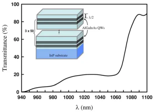
Fig 2. 1 Transmittance spectrum at room temperature for the AR- coated AlGaInAs/InP saturable absorber. Inset, schematic diagram of a periodic
AlGaInAs QW structure. ... 31 Fig 2. 2 Schematic diagram of the experimental setup. HR, high reflection; HT, high
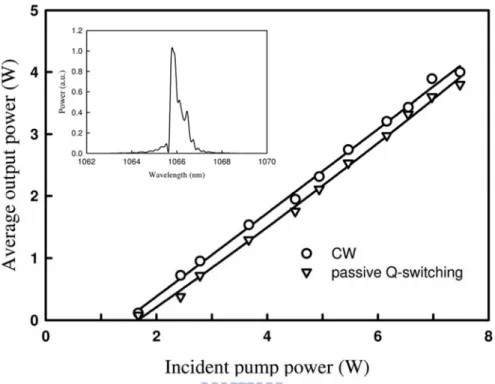
transmission. ... 31 Fig 2. 3 Average output powers at 1066 nm with respect to the incident pump power
in cw and passively Q-switching operations. ... 33 Fig 2. 4 Experimental results for the pulse repetition rate and the pulse energy versus
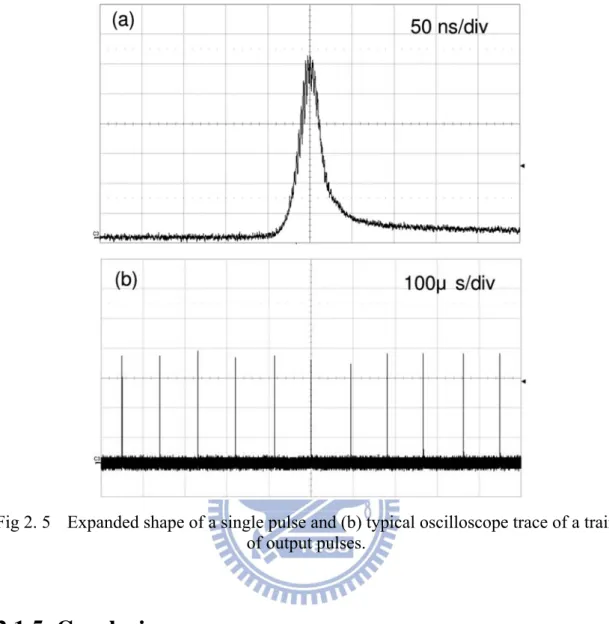
incident pump power. ... 33 Fig 2. 5 Expanded shape of a single pulse and (b) typical oscilloscope trace of a train
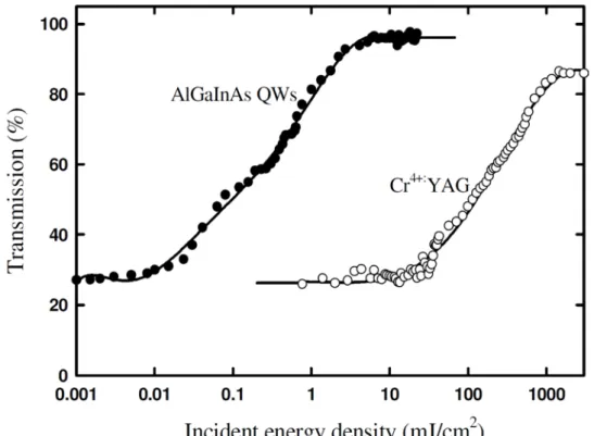
of output pulses. ... 34 Fig 2. 6 Saturation transmission of the AlGaInAs QWs and the Cr4+:YAG crystal. ... 37
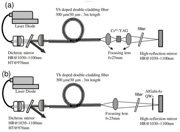
Fig 2. 7 Schematic of diode-pumped PQS Yb-doped fiber lasers. (a) with Cr4+:YA
crystal (b) with AlGaInAs QWs. HR: high reflection; HT: high transmission. ... 38 Fig 2. 8 Dependence of the average output power on the launched pump power for the
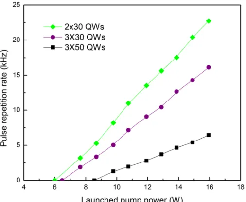
cw and passive Q-switching operations. ... 39 Fig 2. 9 (a) Pulse repetition rate and (b) pulse energy versus the launched pump power.
... 41 Fig 2. 10 Pulse energy versus the resonant wavelength. ... 42 Fig 2. 11 Top: Oscilloscope traces of a typical Q-switched envelope; Bottom:
Oscilloscope traces of a train of Q-switched pulses. ... 42
Chapter 3
Fig 3. 1 Schematic diagrams of three periodic AlGaInAs QWs structures. ... 51 Fig 3. 2 ... Low-intensity transmittance spectrum of the three QW saturable absorbers. ... 51 Fig 3. 3 (a) Setup for the passively Q-switched PCF laser; (b) image of the cross
section of PCF. ... 52 Fig 3. 4 Average output power with respect to launched pump power in CW and
passive Q-switching operations. ... 53 Fig 3. 5 Pulse repetition rates in the passive Q-switching operation versus the
launched pump power. ... 54 Fig 3. 6 Typical oscilloscope traces for the single Q-switched pulses of the lasers
with the saturable absorbers of (a) 2 × 30, (b) 3 × 30, and (c) 3 × 50 QWs,
respectively. ... 56 Fig 3. 7 Typical oscilloscope traces for a train of output pulses of the lasers with the
saturable absorbers of (a) 2 × 30, (b) 3 × 30, and (c) 3 × 50 QWs, respectively. 57 Fig 3. 8 Schematic sketch of the external-cavity optical parametric oscillator
pumped by the passively Q-switched photonic crystal fiber laser. ... 60 Fig 3. 9 Image of cross section of rod-type PCF. ... 62 Fig 3. 10 Transmission spectrum and structure of AlGaInAs saturable absorber. .... 63 Fig 3. 11 Output power of the passively Q-switched PCF laser versus the 976-nm
launched pump power. Inset is the lasing spectrum obtained with 12.5 W of pump power. ... 63 Fig 3. 12 Typical oscilloscope traces of output pulses of the passively Q-switched
PCF laser. (a) pulse shape with 6.3 W of pump power and (b) pulse shape with 13.1 W of pump power ... 64 Fig 3. 13 Schematic sketch of the OPO setup. A half-wave plate and polarization
beam splitter cube were settled in front of OPO to control the input pump
power.... ... ………..65 Fig 3. 14 Output performance of external-cavity OPO. (a) averaged output power
of signal wave versus averaged power of PCF laser and (b) temporal traces of pump and signal wave. ... 66 Fig 3. 15 Tuning curve of signal wavelength versus different operating temperature. Inset is the corresponding conversion efficiency with temperature. ... 66 Fig 3. 16 Setup for the passively Q-switched PCF laser with Cr4+:YAG. ... 70
Fig 3. 17 (a) Average output power with respect to launched pump power in CW and passive Q-switching operations, the inset: typical lasing spectrum. (b) Pulse repetition rate and pulse energy versus launched pump power. ... 71 Fig 3. 18 Typical oscilloscope traces for (a) single Q-switched pulse and (b)
Q-switched pulse train. ... 72 Fig 3. 19 Setup for the intracavity OPO pumped by the passively Q-switched PCF
laser…. ... 72 Fig 3. 20 (a) Average output power at 1515 nm with respect to launched pump
power…… ... 74 Fig 3. 21 General oscilloscope traces for the fundamental (top) and OPO signal
(bottom) output pulses. ... 74
Chapter 4
Fig 4. 1 Schematic diagram of the plano-concave cavity. (b) Equivalent cavity ... 88 Fig 4. 2 Dependence of the mode-to-pump size ratio ω1/ωpa on the pump power for
different pumping spot radii. ... 91 Fig 4. 3 Effective mode area ratio of A/As as a function of the pump power in the
Nd:YVO4/Cr4+:YAG PQS laser with L = 0.9ρ1, ρ1 = 25 mm, ωp = 100 μm. ... 91
Fig 4. 4 Schematic diagram of a diode-pumped Nd:YVO4 laser PQS with a Cr4+:YAG
as a saturable absorber. HR:high reflection. HT:high transmission. ... 92 Fig 4. 5 (a) Dependence of the pulse repetition rate and the pulse energy on the initial
transmission of Cr4+:YAG at the pump power of 5.4 W. (b) Dependence of the
pulse width and the peak power on the initial transmission of Cr4+:YAG at the
pump power of 5.4 W. ... 93 Fig 4. 6 Oscilloscope traces of a single pulse of (a) PQS laser with Cr4+:YAG of
T0 = 0%, (b) PQS laser with Cr4+:YAG of T0 = 40%. ... 94
Fig 4. 7 (a) Scheme of the MOFA setup. HT: high transmission HR: high reflection. (b) Cross section of the PM Yb-doped fiber. ... 95 Fig 4. 8 (a) Average output power and peak power of MOFA with the seed of
repetition rate of 50 kHz as a function of the launched pump power. (b) Oscilloscope traces of a single pulse of the output pulse of the amplifier. (c) Oscilloscope traces of a train of amplified pulses. ... 96 Fig 4. 9 (a) Average output power and peak power of MOFA with the seed of
repetition rate of 25 kHz as a function of the launched pump power. (b) Oscilloscope traces of a single pulse of the output pulse of the amplifier. (c) Oscilloscope traces of a train of amplified pulses. ... 97 Fig 4. 10 End view and side view of the damaged fiber. ... 98 Fig 4. 11 Optical spectra of the MOFAs at the maximum output powers injected by
the seed lasers with T0 = (a) 70 and (b) 40%. ... 98
single-stage rod-like photonic crystal fiber amplifier. HR: high reflection; HT: high ... 103 Fig 4. 13 Relevance of the average output power and the pulse energy with the ... 103 Fig 4. 14 Oscilloscope traces of a train of amplified pulses. (b) Oscilloscope trace . 104 Fig 4. 15 Schematic sketch of the setup of the SHG and THG. AR: anti-reflection. 106 Fig 4. 16 Dependences of the average output power at 532 nm and 355 nm on the . 106 Fig 4. 17 (a) Oscilloscope traces of a train of output pulses of 532 nm (top) and 355
Chapter 1
1.1
Fiber lasers
The fiber lasers are a promising alternative to the conventional solid-state laser systems. They are a result of a merger between of the most innovative and advanced technologies in the laser world – active optical fibers and semiconductor diodes. Fiber lasers offer a superior beam quality and reliability, great output powers, high electrical efficiency, and smaller size.
1.1.1 History
The first fiber laser was demonstrated with erbium and neodymium doped glass lasers in 1960 by Snitzer and Koester [1-3]. It consisted of a coiled neodymium-doped fiber transversely pumped by a flash lamp, and emitted around 1060 nm with a multimode output. A few years later, the first longitudinally pumped fiber laser, pumped by a laser diode, was demonstrated by Stone and Burrus [4]. The breakthrough in the fabrication of rare-earth doped silica fiber came in 1985 thanks to the development of solution doping as a way to incorporate rare earths into performs fabricated through modified chemical vapour deposition (MCVD) [5]. Later, a Nd-doped silica single-mode fiber laser was demonstrated by Mears et al. [6]. Since then fiber lasers made with various rare-earth dopants including Nd, Er, Yb, Ho, Dy, and Eu have been investigated [7-8]. However, it is the erbium-doped fiber amplifier (EDFA) for optical telecommunications which catalyzes telecom research. The development of EDFAs, which was spurred by important telecommunication market demands and backed by the immense resources of the telecommunication industry, quickly led to the wide availability of knowledge, components, technologies, and equipment relevant to the development of optical fiber lasers. This, in turn, led to an extensive amount of research being conducted on rare-earth-doped fiber lasers covering continuous wave (CW) lasers, Q-switched lasers, mode-locked lasers, upconversion lasers, and single-frequency lasers in the late 1980s and early 1990s.
Two important technologies boost up the output power of fiber lasers. One is the invention of double-cladding fibers, and the other is rapid process in high power laser diodes.
Initially, the average power from a single-mode fiber laser pumped by the single-mode pump diode was too low for most industry applications. The pump diode can only be coupled into the core of the fiber, so just the single-mode pump diode
which has low-power output can do this work. Consequently the output power of a single-mode fiber laser was confined to the subwatt levels. Higher-power pump diodes with large diameter have multi-mode output, and they can’t be coupled efficiently to the core of the fiber. Thus a double-cladding fiber scheme was proposed by Snitzer in 1988 to increase the coupling efficiency of multi-mode pump diodes[9]. The double- cladding fiber, which has a small rare-earth-doped single-mode core embedded in a much larger multimode pump guide, effectively behaves like a brightness converter, which allows conversion of high-power multi-mode pump light to a single-mode laser beam guided in the rare-earth doped single-mode core. The double-cladding fiber’s configuration will be described in detail later.
In addition to continuous improvements in crystal growth technologies and the purity of materials sources, refinements in laser design, such as increased efficiency, improved facet passivation technology, robust die attach and advanced heat sinking, drive the growth in the output power of pump diodes [10]. As showed in Fig. 1.1 [11] , both single-mode and multi-mode laser diodes have about 15 percent increase on the output power every year. Nowadays kw-level commercial products of laser diodes are available [12].
Fig 1. 1 Growth in multimode and single-mode reliable continuous waves power for 9XX-nm [11].
1.1.2 Advantages
An optical fiber is a cylindrical dielectric waveguide made of low-loss material such as a silica glass. It has a central core with refractive index n1 in which the light is
guided, embedded in an outer cladding of slightly lower refractive index n2 (Fig. 1.2).
Light rays, which incident the core at angles lower than the critical angle: arcsin
c NA
,
(1) where NA, numerical aperture:
2 2
1 21 2
NA n n , (2) undergo total internal reflection and are guided through the core without the refraction. Rays of greater inclination to the fiber axis lose part of their energy into the cladding at each reflection and are not guided [13]. The V number:
2 2
1 2 1 2 2 r 2 r V NA n n , (3)
depending on the wavelength λ, the fiber core radius r and the numerical aperture, determines the number of modes of a step-index fiber, and is related to n1 and n2 [14].For single-mode guidance, the V number must be below 2.405 [15]. As showed in Fig. 1.3, thus an optical fiber can be designed properly to support only the lowest-order mode, fundamental LP01 mode, without the spatial mode control. So the fiber lasers
have excellent beam quality which is very important in many applications [16].
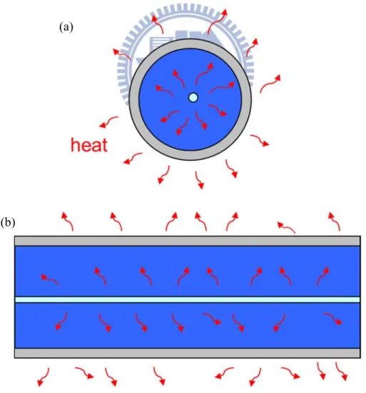
Another significant benefit is the outstanding heat-dissipation capability [17-19], because the fiber has a long length with a large ratio of heat-dissipating surface to active volume, as showed in Fig. 1.4. It essentially does not have the active cooling so that the laser system can be simplified.
Fig 1. 3 The optical fiber can be designed to support multimode or single mode.
Fig 1. 4 An optical fiber has a good thermal dissipation due to (a) a large ratio of heat-dissipating surface to active volume and (b) a long length
(a)
1.2 Fiber concept
1.2.1 Ytterbium doped fiber
Ytterbium (Yb) is a chemical element belonging to the group of rare earth metals. In laser technology, it has acquired a prominent role in the form of the trivalent ion Yb3+, which is used as a laser-active dopant in a variety of host materials, including
both crystals and glasses. The energy level of Yb3+ ion which consists of two-manifolds;
the ground manifolds (2F
7/2) and a well separated excited manifolds (2F5/2), which
include four and three Stark shifted levels respectively is shown in Fig. 1.5 [20]. Ytterbium doped fiber has a number of interesting properties for high-power fiber lasers. The first property is the Yb3+ ion’s simple system with low quantum defect which
means the pump wavelength is closer to the lasing wavelength. Low quantum defect equals less heat generation, which is a huge plus for high-power lasers. The simple system of ytterbium is also beneficial, because there is no need to worry too much about excited state absorption and cooperative upconversion, both of which are channels for power loss. The upconversion process can also lead to photodarkening, which compromises the long-term reliability of an optical fiber laser. Unlike for Er3+
ions, the manifolds of Yb3+ ion give distinct transitions in absorption and emission
spectra. For a pump wavelength of 976 nm, a → e is used, especially for cladding pumped optical fibers due to high pump absorption. For pump wavelengths around 915 nm, a → f is sometimes used to provide more tolerance in pump wavelength control; this also allows higher gain per unit length due to the much higher inversion possible when pumped around 915 nm. Two transitions, one at 1025 nm, e → b, and one at 1080 nm, e → c, dominate the emission spectra.
The effective absorption and emission cross sections of Yb-doped fibers are shown in Figure 1.6 [21]. The gain bandwidth of the laser transitions is large due to the overlapping of Stark shifted levels which allows for wide wavelength tuning ranges (0.9 μm up to 1.2 μm), or for generating ultrashort pulses in mode-locked lasers. The upper-state lifetimes are relatively long, around 1.5 ms [21], which is beneficial for Q-switching.
Fig 1. 5 Energy levels of Yb3+ ions.
1.2.2 Double-cladding fibers(DCFs)
Double-cladding fibers are an important technology in the area of active fiber optics, particularly for high-power fiber lasers [22,23]. In the past a fiber laser based on an ordinary doped single-mode fiber can generate a diffraction-limited output, but it restricts the pump sources to those with diffraction-limited beam quality and thus normally to those with low power. On the other hand, the use of multimode fibers usually leads to poor beam quality. This problem can be solved with the invention of double-cladding fiber designs. These have a pump cladding (inner cladding) around the fiber core, which is itself surrounded by an outer cladding of even lower refractive index. The pump cladding, often having a substantially larger diameter than the fiber core and also a higher numerical aperture, constitutes a multimode waveguide into which high-power pump light can be launched easily and efficiently, even if the pump beam quality is not that great. The refractive index of the core is still higher than that of the pump cladding, so that it supports a single guided mode, or sometimes a few modes. Pump light launched into the inner cladding also gets into the fiber core, where it can be absorbed by laser-active ions. The pump light is gradually absorbed by active core during propagating in the undoped inner cladding. Figure 1.7 shows how pump light is injected into the inner cladding, while signal light is injected into the fiber core and remains there. Thus, the structure of DCF is absolutely a good brightness converter.
However, with increasing the diameter of the pump guide, the number of rays which do not interact with the absorbing core also increase. In particular, helical rays propagating in a meander-like path in the inner cladding have negligible overlap with the core and may be lost at the output side. Destroying the symmetry to make the rays irregular will be helpful to increase the absorption efficiency. Several shapes of inner cladding are proposed to solve the problem [24-26]. Fig. 1.8 shows the different inner cladding designs.
Fig 1. 8 Various designs of double-clad fibers
1.2.3 Photonic crystal fibers(PCFs)
Although DCF can be useful for scaling laser output power, there is some restriction. The limiting factor is the nonlinear effects such as stimulated Brillouin scattering (SBS), stimulated Raman scattering (SRS), self-phase modulation (SPM) and four-wave mixing (FWM) [27]. The nonlinearity of a fiber scales with the fiber length and is inversely proportional to mode-field area. To overcome this issue, specialty fiber of increasingly large diameter and high pump absorption is necessary in the reduction of fiber length. To date, with the development of the fabrication technology modern optical fibers are investigated. Photonic crystal fibers (PCFs), also known as microstructure fibers (MFS), are currently subject of intense research [28-30]. Photonic crystal fibers (PCFs) were first demonstrated in the late 1990s [31,32]. Its potential for achieving single-mode operation with large cores was realized very early on[33]. A photonic crystal fiber obtains its waveguide properties not from a spatially varying glass composition but from an arrangement of very tiny and closely spaced air holes
which go through the whole length of fiber. It is drawn from a hexagonal stack of capillaries, with typically one to seven capillaries replaced by rods in the center. Pressurization of the airholes is typically used to keep the holes from collapsing from surface tension during drawing. The center rods form the core. The composite cladding material of glass and air makes it easy to achieve a very low refractive index contrast between the core and the composite cladding, consequently providing much better control at achieving fibers with large mode field diameters and low NAs [34].
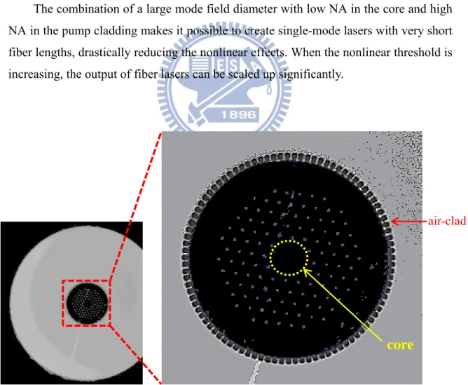
The pump cladding in PCFs is typically made with a layer of airholes with very thin glass webs (as showed in Fig. 1.9). This structure has been demonstrated to be capable of providing an effective pump NA of ~1. In practice, the glass webs must be made thick enough to allow cleaving of the end face [35]. This typically limits pump NAs to ~0.6, which is larger than what is possible with low-refractive index polymers. As a result, high power pump diodes with high NA can be used.
The combination of a large mode field diameter with low NA in the core and high NA in the pump cladding makes it possible to create single-mode lasers with very short fiber lengths, drastically reducing the nonlinear effects. When the nonlinear threshold is increasing, the output of fiber lasers can be scaled up significantly.
Fig 1. 9 Microscope picture of a 7-cell core Yb-doped air-clad PCF.
air-clad
1.3
Q-switching
Q-switching is a technique for obtaining high pulse power [36]. The quality factor Q can be defined as the ratio of the energy stored in the cavity to the energy loss per cycle [37]. This technique is use to alter the quality factor of the resonant cavity. Hence the higher the quality factor, the lower the loss. While the laser pumping is in the process, it is necessary to keep the cavity itself from lasing by greatly increasing the loss. Then a large population inversion is developed, we restore, or “switch”, the cavity Q back to its usual large value. The result is a very short, intense burst of laser output which dumps all the accumulated population inversion in a single short laser pulse. The peak power of the resulting pulse exceeds that obtainable from the continue-wave laser by several orders of magnitude. Lasers to which the Q-switching technique is applied are called Q-switched lasers. The possibility of Q-switched laser was first proposed by Hellwarth in 1961 [38]. The first experimental observation of Q-switched pulse behavior was made by McClung and Hellwarth in 1962 using an electrooptic Q-switch in a ruby laser [39]. A complete theoretical treatment was completed by Wagner and Lengyel in 1963 [40] and a simplified version was given by Wang in the same year [44]. A more elaborate treatment including numerical modeling was performed by Fleck in 1970 [42].
There are several methods that have been developed to achieve switching the Q of the resonator. A key requirement for all these methods is that the cavity Q is changed quickly enough that the population inversion remains nearly constant during the switching process. Generally, a switching time of ~ 10 ns is desirable. When the switching time is too long, multiple pulses may result as the population inversion oscillates above and below threshold. The Q-switching techniques can roughly divide into two categories, active Q-switching and passive Q-switching. For active Q- switching, the losses are modulated with an active control element, typically either an acousto-optic or electro-optic modulator [43,44]. Here, the pulse is formed shortly after an electrical trigger signal arrives. For passive Q-switching, the losses are automatically modulated with a saturable absorber [45,46] . Here, the pulse is formed as soon as the energy stored in the gain medium has reached a high enough level. In the following section, I will discuss the most commonly used methods, including mechanical switches,electro-optic switches, acousto-optic switches, and saturable absorbers.
1.3.1 Types of Q-switching
(a) Mechanical Q-switching
A simple mechanical Q-switching is illustrated in Fig. 1.10. One mirror in the laser cavity is fixed in place, and the other rotates at a high speed about a vertical axis. The Q of the cavity is then high only when the mirrors are parallel within some tolerance. Restricted to the nature of the mechanism, the switching time is so long that multiple pulses will be generated. Mechanical Q-switches are the simplest and least expensive of Q-switches, but they possess relatively short lifetimes and are not robust in harsh environments.
Fig 1. 10 Q-switching can be achieved by rotating one of the laser mirrors at a high speed.
(b) Electro-optics Q-switching
The electro-optics switch is formed by placing two optical elements in the path of the beam inside the cavity, as showed in figure 1.11. The first element is a polarizer, oriented to allow transmission of only one polarization of light. The second element is a Pockels cell , a nonlinear crystal that rotates the polarization of the light when a high voltage is applied. With no applied voltage, vertically polarized light is efficiently transmitted through both elements, and the cavity Q is high. When an appropriate voltage is applied, vertically polarized light is rotated to horizontal polarization in two passes through the nonlinear crystal, and this light is then blocked by the polarizer. The net result is a low Q value when the voltage is applied. The Q-switching process proceeds by initially applying a high voltage to the Pockels cell, and then rapidly removing the voltage, which switches the Q from low to high. This type of Q-switching is in common use, but requires attention to safety because of the high voltages involved.
Fig 1. 11 Electrooptic Q-switching is achieved by placing a Pockels cell and polarizer in the laser cavity. Vertical polarization is maintained when V = 0. When a voltage V
= Vπ/2 is applied, the polarization is rotated from vertical to horizontal after passing
through the Pockels cell twice.
(c) Acousto-optic Q-switching
In this method, a transparent crystal is inserted into the laser cavity, and high intensity acoustic waves are generated in the crystal by an attached piezoelectric transducer (PZT), as showed in figure 1.12. The acoustic waves create a periodic variation of the crystal’s refractive index, which forms a volume-phase grating. Light that is diffracted from this grating increases the cavity loss and decreases Q. The Q-switching process starts with the acoustic waves turned on, such that Q is low enough to prevent lasing. The acoustic waves are then quickly turned off, which increases the Q and enables lasing.
(d) Passive Q-Switching
So far I have considered active Q-switching, in which the time and duration of the change in Q are under active control. The voltage pulse applied to the Pockels cell, or the RF power sent to the acousto-optic deflector, occurs with a timing and repetition rate determined by the user. An alternative approach is to let the laser cavity Q-switch itself, independently of actions by the user. Such a method is termed passive
Fig 1. 12 In acousto-optic Q-switching, sound waves create a refractive-index grating that diffracts part of the beam, spoiling the Q of the cavity.
Figure 1.13 depicts that passive Q-switch consists of an optical element, such as a cell filled with organic dye or a doped crystal, which has a transmission characteristic as shown in Fig. 1.14 [47]. The material becomes more transparent as the fluence increases, and at high fluence levels the material saturates or bleaches, resulting in a high transmission. The bleaching process in a saturable absorber is based on saturation of a spectral transition. If such a material with high absorption at the wavelength is placed inside the laser resonator, it will initially prevent laser oscillation. As the gain increases during a pump pulse and exceeds the round-trip losses, the intracavity power density increases dramatically causing the passive Q-switch to saturate. Under this condition the losses are low and a Q-switch pulse builds up. Since the passive Q-switch is switched by the laser radiation itself, it requires no electro-optic driver, or RF generator. As an alternative to active methods, the passive Q-switch offers the advantage of an exceptional simple design, which leads to very small, robust, and low-cost systems.
Fig 1. 13 Placing a saturable absorber inside the laser cavity causes the laser to self-Q-switch.
Fig 1. 14 Nonlinear transmission of a saturable absorber versus fluence normalized to the saturation fluence Es of the absorber [47].
1.3.2 Passively Q-switching laser
Lasers which use the passively Q-switching technique are called passively Q- switching lasers, and so are actively Q-switching lasers. Compared with active Q-switching lasers, passively Q-switching lasers have not only the simplicity of implementation but also the advantages of the generation of a well-defined pulse energy and duration that is insensitive to pumping conditions as long as the pump energy is above the Q-switching threshold.
Originally, saturable absorbers used in passively Q-switching lasers were based on different organic dyes, either dissolved in an organic solution or impregnated in thin films of cellulose acetate [48,49]. The poor durability of dye-cell Q-switches, caused by the degradation of the light sensitive organic dye, and the low thermal limits of plastic materials severely restricted the applications of passive Q-switches in the past. The emergence of crystals doped with absorbing ions or containing color centers has greatly improved the durability and reliability of passive Q-switches. The first new material to appear was the F2-:LiF color center crystal [50]. The color centers are induced in the
crystal by irradiation with gamma, electron, or neutron sources. Today, the most common material employed as a passive Q-switch is Cr4+: YAG [51].
In additional to own the desirable chemical, thermal, and mechanical properties required for long life, Cr4+: YAG crystals have characteristics of large absorption cross
section and long excited-state lifetime required for optical absorption. The optical energy-level of Cr4+:YAG crystals is shown in Fig. 1.15. The Cr4+:YAG crystal is a
four-level system at the absorption band of 1.0~1.1 μm. The solid line and the dash line indicate radiative and non-radiative transitions respectively. The spontaneous emission occurs via transitions from level 3 to the metastable level 2 and the lifetime τ3-2 is in the
order of 3~4 μs [52,53]. Excited-state absorption (ESA) is included in this figure and the lifetime for the corresponding decay is of the order of ps [54,55]. The ESA acts a loss in the absorption process and results in a degradation of final transmission of saturable absorbable. Fortunately the cross-section of ESA of Cr4+: YAG is small
compared to that of ground-state. However the excited cross section can not be neglected and they have been studied for years. The values of the cross sections for ground state absorption and excited state absorption are not known exactly so far and can vary by more than one order of magnitude due to measured cross section depending on the property of incident pump beam such as the pulse repetition rate and pulse duration, and concentration and homogeneity of Cr4+:YAG crystals. Table 1.1 shows
the reported results for the σgs and σes.
In addition to Cr4+:YAG crystals, semiconductor-based saturable absorber is
another most common material employed as a passive Q-switch recently. Semiconductor saturable absorbers offer more flexible parameters such as operating wavelength, modulation depth, unsaturated and saturated absorption, and recovery time. They are achieved by controlling band gap parameters, number of QWs, co-doping or growth technology [59,60]. To date semiconductors have proved to be one of the
excellent candidates for passively Q-switching fiber lasers [61,62]. The main advantage of taking semiconductors material as saturable absorber is their short recovery time in the time scale of ns to ps. Compared with Cr4+: YAG crystals, semiconductors are able
to provide large absorption cross section profit capturing photons in Q-switched lasers. Among the semiconductor saturable absorbers, InGaAs and AlGaInP materials are the most common ones in passively Q-switching lasers [61,63-64]. Recently AlGaInAs quaternary alloys semiconductors have been confirmed with the merits of larger conduction band offset [65] (meaning a better electron confinement than InGaAsP materials) and lattice-matching to the InP substrate. It is note that choice of InP based alloys provides higher thermal conductivity than GaAs or AlGaAs based alloys [66, 67]. Figure 1.16 shows the available range of operating wavelength of AlGaInAs. AlGaInAs can be alloyed with the ternary alloys of InAlAs and InGaAs. It is noted they are both lattice-matched to InP substrates with lattice constant of 5.87A. The energy gap of AlGaInAs is determined by the composition of InAlAs and InGaAs and is tunable from 0.75eV to 1.37eV (1.65μm to 0.9μm). The advantages reveal that AlGaInAs quaternary alloys are potentially applicable as saturable absorbers in passively Q-switching lasers [68]. Figure 1.17 shows the structure of the AlGaInAs saturable absorber.
Fig 1. 15 Schematic energy-level diagram of Cr4+: YAG with ESA. The solid lines
indicate optical transitions and the dashed lines indicate non-radiative transitions. The non-radiative relaxation 4-3, 2-1, and 5-3 are much faster than the lifetime of the
σgs( 10-18 cm2) 7±0.8 2±0.4 0.87±0.08
σes( 10-19 cm2) 2±0.3 2±0.4 2.2±0.2
σes /σgs 0.286 0.1 0.25
Ref. [56] [57] [58] Table 1. 1 The reported values of σgs andσes of the Cr4+:YAG crystal
Fig 1. 16 Energy gap versus lattice constant in InGaAs-InP-InAlAs system
Fig 1. 17 Structure of periodic AlGaInAs QWs saturable absorbers. The periodic structure means the region of the saturable absorbers consist periodic groups of several
QWs, spaced at half-wavelength intervals by barrier layers.
5.4 5.5 5.6 5.7 5.8 5.9 6.0 6.1 0.0 0.5 1.0 1.5 2.0 2.5 InP InAs InGaAS InAlAs GaAs Energ y g ap (eV)
Lattice constant (A) AlAs Si AlGaAs λ/2 Periodic QWs AlGaInAs QWs InP substrate barrier InP window layer
λ/2 Periodic QWs AlGaInAs QWs InP substrate barrier InP window layer
1.4 Motivation
Compared with conventional bulk solid-sate lasers, fiber lasers have some intrinsic merits and have seen a tremendous growth in both industrial and research markets. Fiber lasers have excellent thermal properties. Their high ratio of heat-dissipating surface to active volume allows efficient thermal dissipation and usually they do not need active cooling. In addition, the property of wave guide tends to reduce thermal distortion of the beam and achieves excellent beam quality independent of the power. Fiber lasers can be fabricated robustly with long lifetime stability and reliability. The cladding pump scheme has enabled the coupling of high power LDs with large NA into the fiber lasers. A pulsed laser may be advantageous over a continuous one in some applications, such as remote sensing, material processing, and medical needs [69-71], due to its higher peak power.
Recently there has been considerable interest in studying Yb doped fiber lasers because of their beneficial properties for a number of applications. With a small quantum defect (difference in the energy of the pump photons and the emitted photons), Yb doped fiber lasers are suitable for high power operation with reduced thermal loading. The relatively long upper-state lifetime of Yb enables more efficient pumping from a given diode pump source and storage of a large amount of energy which is of benefit for Q-switching operation. Many actively and passively Q-switched DC Yb fiber lasers have been reported to date [72-77]. The emission spectrum of Yb is also broad which allows wide wavelength tuning or multi-wavelength lasing [78-81].
Passive Q-switching (PQS) is a sophisticated and an efficient technique to create high-pulse-energy and high-peak-power pulses. Besides, PQS lasers are more compact and lower cost than the active Q-switching cause of that they utilize saturable absorbers (SAs) in replace of acoustic-optic or electro-optic modulators as the Q-switch. Fiber-type SA [82-84] offers the in-line configuration, nevertheless they are restricted by modulation depth to deliver high-pulse-energy laser. Crystal-based and semi- conductor-based SAs are other choices of passive Q-switch. Their high mechanical robustness and well-developed fabrication process make them more common in Q-switched fiber lasers [85-87]. In the spectral region of 1.0~1.1 μm, Cr4+:YAG
crystals [85] and InGaAs/GaAs quantum wells (QWs) [87] have been adopted to Q-switch fiber lasers. However, the output pulse energy with InGaAs SESAMs in passively Q-switched lasers are limited by the lattice mismatch with the substrate GaAs
for the spectral region of above 1.0 μm. As a consequence, the output pulse energies and the conversion efficiencies with InGaAs/GaAs QWs in passively Q-switched lasers are generally significantly lower than those with Cr4+:YAG crystals. Recently, an
AlGaInAs with a periodic QW/barrier structure has been exploited to be an efficient saturable absorber for a passively Q-switched Nd:YVO4 laser [88]. Compared with
InGaAsP materials, the AlGaInAs quaternary alloy with a larger conduction band offset is confirmed to offer a superior electron confinement in the 0.84-1.65 μm spectral region [89-91]. Nevertheless, AlGaInAs/InP QWs have not been employed to passively Q-switching Yb-doped fiber lasers. Therefore, it is interesting to stuy a passively Q- switching Yb-doped fiber laser with an AlGaInAs/InP QWs saturable absorber, and have a comparison between Cr4+:YAG crystal and AlGaInAs QWs.
To achieve higher pulse energy, it is necessary to enlarge the active volume of the gain medium, corresponding to the doped core size of the fiber. However, the conventional double-cladding fibers suffer from mode-quality degradation and their long lengths usually lead to long pulse widths and low peak powers. For improving these deficiencies, photonic crystal fibers have been developed to provide large single-mode cores and high absorption efficiencies. So far passively Q-switching Yb- doped photonic crystal fiber lasers with AlGaInAs QWs or Cr4+:YAG crystal as the
saturable absorber have not been investigated, so I have some studies about these. The configuration of master oscillator fiber amplifier (MOFA) consists of a seed laser and a fiber amplifier for boosting the output power. Because the output performance is affected by the low-power seed laser which can be easily modulated, shorter pulse width can be attained by shortening the cavity length of the seed laser. Therefore, it is necessary to use the MOFA to have higher-peak-power pulse lasers. Thus I use the MOFA to have some studies.
Reference
1. E. Snitzer, "Proposed fiber cavities for optical lasers", J. Appl. Phys. 32, 36-39 (1961).
2. E. Snitzer, "Optical maser action of Nd3+ in a barium crown glass", Phys. Rev.
Lett. 7, 444-446 (1961).
3. C. J. Koester, and E. Snitzer, "Amplification in a fiber laser", Appl. Opt. 3, 1182-1186 (1964).
4. J. Stone, and C. A. Burrus, "Neodymium-Doped Silica Lasers in End-Pumped Fiber Geometry", Appl. Phys. Lett. 23(7), 388-389 (1973).
5. Hegarty, J., Broer, M. M., Golding, B., Simpson, J. R., and MacChesney, J. B., “Photon Echoes Below 1 K in a Nd3-Doped Glass Fiber,” Phys. Rev. Lett. 51,
2033-2035 (1983).
6. R. J. Mears, L. Reekie, S. B. Poole, and D. N. Payne, "Neodymium-doped silica singlemode fibre laser", Electron. Lett. 21, 738-740 (1985).
7. S. B. Poole, D. N. Payne, R. J. Mears, M. E. Fermann, and R. I. Laming, “Fabrication and characterization of low-loss optical fibers containing rare earth ions”, J. Lightwave Technol. LT-4 (7), 870-876 (1986)
8. J. E. Townsend et al., “Solution-doping technique for fabrication of rare earth doped optical fibres”, Electron. Lett. 23, 329-331 (1987)
9. E. Snitzer, H. Po, F. Hakimi, R. Tumminelli, and B. C. McCollum, "Double-clad, offset core Nd fiber laser", in Proc. Opt. Fiber Sensors, New Orleans, 1988, post-deadline paper PD5.
10. Welch, D. F., “A Brief History of High-Power Semiconductor Lasers”, IEEE J. Sel. Top. Quant. Electron. 6, 1470–1477 (2000).
11. H. Injeyan and G. D. Goodno, High-Power Laser Handbook, McGraw-Hill (2011).
12. Information available from DILAS Diodenlaser GmbH: http://www.dilas.com/ 13. B. E. A. Saleh and M. C. Teich, Fundamentals of photonics, John Wiley & Sons,
Inc. (1991).
14. A. W. Snyder and J. D. Love, Optical Waveguide Theory, Chapman and Hall, London (1983).
15. D. Gloge, “Weakly guiding fibers”, Appl. Opt. 10 (10), 2252 (1971)
and its application”, Laser Tec. 30(4), 438-441 (2006).
17. K. I. Ueda, "High power fiber lasers", in Proc. Pacific Rim Conference on Lasers and Electro-Optics (CLEO), Chiba, 2001.
18. L. Zenteno, "High power double clad fibre lasers", J. Lightwave Technol. 11(9), 1435-1447, (1993).
19. D. C. Brown and H. J. Hoffman, "Thermal, stress, and thermo-optic effects in highaverage power double-clad silica fiber lasers", IEEE J. Quantum Electron. 37(2), 207 (2001).
20. K. Lu and N. K. Dutta, "Spectroscopic properties of Yb-doped silica glass", J. Appl. Phys. 91,576–581 (2002).
21. R. Paschotta, J. Nilsson, A. C. Tropper, and D. C. Hanna, “Ytterbium-doped fiber amplifiers,” IEEE J. Quantum Electron. 33, 1049-1056 (1997).
22. A. Tunnermann, T. Schreiber, F. Roser, A. Liem, S. Hofer, H. Zellmer, S. Nolte, and J. Limpert, "The renaissance and bright future of fibre lasers," Journal of Physics B-Atomic Molecular and Optical Physics 38, S681-S693 (2005).
23. J. Limpert, F. Roser, S. Klingebiel, T. Schreiber, C. Wirth, T. Peschel, R. Eberhardt, and A. Tunnermann, "The rising power of fiber lasers and amplifiers," Ieee Journal of Selected Topics in Quantum Electronics 13, 537-545 (2007). 24. V. Doya, O. Legrand, and F. Mortessagne, "Optimized absorption in a chaotic
doubleclad fibre amplifier", Opt. Lett. 26(12), 872 (2001).
25. P. Leproux, S. Février, "Modeling and optimization of double-clad fibre amplifiers using chaotic propagation of the pump", Opt. Fibre Technol. 7(4), 324 (2001).
26. A. Liu, K. Ueda, "The absorption characteristics of circular, offset, and rectangular double-clad fibers," Opt. Commun. 132(5-6) 511 (1996).
27. G. P. Agrawal, Nonlinear Fiber Optics, Academic, San Diego, Calif. (1995). 28. A. Bjarklev, J. Broeng, A.S. Bjarklev, Photonic crystal fibres, Kluwer Academic
Publishers (2003).
29. P. Russell, "Photonic crystal fibers," Science 299, 358-362 (2003). 30. J. C. Knight, "Photonic crystal fibres," Nature 424,847-851 ( 2003).
31. J. C. Knight, T. A. Birks, P. Russell, and D. M. Atkin, "All-Silica Single-Mode Optical Fiber with Photonic Crystal Cladding," Opt. Lett. 21, 1547-1549 (1996). 32. T. A. Birks, J. C. Knight, and P. Russell, "Endless Single-Mode Photonic Crystal
33. J. C. Knight, T. A. Birks, R. F. Cregan, P. Russell, and J. P. de Sandro,“Large Mode Area Photonic Crystal Fiber,”Electron. Lett. 34, 1347-1348 (1998).
34. J. Limpert, A. Liem, M. Reich, T. Schreiber, S. Nolte, H. Zellmer, A. Tunnermann, et al., "Low-Nonlinearity Single-Transverse-Mode Ytterbium-Doped Photonic Crystal Fiber Amplifier," Opt. Express 12, 1313-1319 (2004).
35. K. P. Hansen, J. Broeng, A. Petersson, M. D. Nielsen, P. M. W. Skovgaard, et al., "High-power photonic crystal fibers, " Proc. of SPIE, 6102, 61020B-1 (2006). 36. C. C. Wang. "Optical giant pulses from a Q-switched laser," Proc. of the IEEE, 51
(12), 1767-1767 (1963).
37. J. T. Verdeyen, Laser electronics, Prentice-Hall third ed. (1995).
38. R. W. Hellwarth, "Control of Fluorescent Pulsations," Advances in Quantum Electronics, ed J. R. Singer, 334-341 (1961).
39. F. J. McClung and R. W. Hellwarth. "Giant Optical Pulsations from Ruby," J. Appl. Phys. 33, 828 (1962).
40. W. G. Wagner and B. A. Lengyel, "Evolution of the Giant Pulse in a Laser," J. Appl. Phys.34, 2040(1963).
41. C. C. Wang, "Optical giant pulses from a Q-switched laser," Proc. IEEE 51(12), 1764 (1963).
42. J.A. Fleck, " Ultrashort-Pulse Generation by Q-Switched Lasers," Phys. Rev. B 1 (1), 84 (1970).
43. J. Limpert, N. Deguil-Robin, S. Petit, I. Manek-Hönninger, F. Salin, P. Rigail, C. Hönninger, and E. Mottay, "High power Q-switched Yb-doped photonic crystal fiber laser producing sub-10 ns pulses," Appl. Phys. B 81, 19 (2005).
44. O. Schmidt, J. Rothhardt, F. Röser, S. Linke, T. Schreiber, K. Rademaker, J. Limpert, S. Ermeneux, P. Yvernault, F. Salin, and A. Tünnermann, “ Millijoule pulse energy Q-switched short-length fiber laser, ” Opt. Lett. 32, 1551 (2007). 45. J. Dong, P. Deng, Y. Liu, Y. Zhang, J. Xu, W. Chen and X. Xie, "Passively
Q-switched Yb:YAG laser with Cr4+:YAG," Appl. Opt. 40, 4303 (2001).
46. G. J. Spuhler, R. Paschotta, M. P. Kullberg, M. Graf, M. Moser, E. Mix, G. Huber, C. Harder and U. Keller, "A passively Q-switched Yb:YAG microchip laser ," Appl. Phys. B 72, 285 (2001).
47. W. T. Rhodes, et al., Solid-State Laser Engineering, Springer sixth ed. (2006). 48. P. P. Sorokin and J. R. Lankard, "Stimulated emission observed from an organic
49. F. P. Schäfer, et al., "Organic dye solution laser," Appl. Phys. Lett. 9 (8), 306 (1966)
50. V. A. Buchenkov, A. G. Kalintsev, A. A. Mak, L. N. Soms, A. I. Stepanov, and A. A. Tarasov, "Characteristics of YAG:Nd3+ lasers passively Q switched by LiF
crystals containing color centers," Sov.J. Quantum Electron. 11(10), 1367-1368 (1981)
51. H. Ridderbusch and T. Graf, "Saturation of 1047- and 1064-nm absorption in Cr4+:YAG crystals," IEEE J. Quantum Electron. 43 (2), 168 (2007)
52. Y. Shimony, Z. Burshtein, and Y. Kalisky, "Cr4+ :YAG as passive Q-switch and
brewster plate in a pulsed Nd:YAG laser," IEEE J. Quantum Electron. 31, 1738-1741 (1995).
53. Z. Burshtein, P. Blau, Y. Kalisky, Y. Shimony, and M. R. Kokta, "Excited-state absorption studies of Cr4+ ions in several garnet host crystals," IEEE J. Quantum
Electron. 34, 292-299 (1998).
54. S. H. Yim, D. R. Lee, B. K. Rhee, and D. Kim, "Nonlinear absorption of Cr4+ :YAG studied with lasers of different pulsewidth," Apl. Phys. Lett. 73,
3193-3195 (1998).
55. N. I. Borodin, V. A. Zhitnyuk, A. G. Okhrimchuk, and A. V. Shestakov, "Oscillation of a Y3 Al5 O12 : Cr4+ laser in wave length region of 1.34-1.6 μm,"
Izvestiya Akademii Nauk SSSR 54, 1500-1506 (1990).
56. Z. Burshtein, P. Blau, Y. Kalisky, Y. Shimony, M.R. Kokta, "Excited-State Absorption Studie of Cr4+ Ions in Several Garnet Host Crystals," IEEE J. of
Quantum Electron. 34, 292–299 (1998).
57. R. Moncorge, H. Manna, F. Deghoul, Y. Guyot, Y. Kalisky, S.A. Pollack, E.V. Zharikov, M. Kokta, "Saturable and excited state absorption measurements in Cr4+:LuAG single crystals," Optics Commun. 132, 279–284 (1996).
58. Y. Shimony, Z, Burshtein and Y. Kalisky, "Cr4+:YAG as passive Q-switch and
Brewster plate in a pulsed Nd:YAG laser," IEEE J. Quantum Electron. 31, 1738-1741 (1995).
59. M. Haiml, R. Grange, U. Keller, "Optical characterization of semiconductor saturable absorbers," Appl. Phys. B 79, 331 (2004).
60. U. Keller, K. J. Weingarten, F. X. Kärtner, D. Kopf, B. Braun, I. D. Jung, R. Fluck, C. Hönninger, N. Matuschek, J. Aus der Au, "Semiconductor saturable absorber mirrors (SESAMs) for femtosecond to nanosecond pulse generation in solid-state
lasers," IEEE J. Selected Topics in Quantum Electronics (JSTQE) 2, 435-453 (1996).
61. T. Hakulinen and O. G. Okhotnikov, "8 ns fiber laser Q switched by the resonant saturable absorber mirror," Opt. Lett. 32, 2677-2679 (2007).
62. S. Kivistö, R. Koskinen, J. Paajaste, S. D. Jackson, M. Guina, and O. G. Okhotnikov, "Passively Q-switched Tm3+, Ho3+-doped silica fiber laser using a
highly nonlinear saturable absorber and dynamic gain pulse compression," Opt. Express 16, 22058-22063 (2008).
63. J.Y. Huang, H.C. Liang, K.W. Su, H.C. Lai, Y.F. Chen and K.F. Huang, "InGaAs quantum-well saturable absorbers for a diode-pumped passively Q-switched Nd:YAG laser at 1123 nm," Appl. Opt. 46, 2, 239-242 (2007).
64. A. Li, S.C. Liu, K.W. Su, Y.L. Liao, S.C. Huang, Y.F. Chen, K.F. Huang, "InGaAsP quantum-wells saturable absorber for diode-pumped passively Q-switched 1.3-μm lasers," Appl. Phys. B 84, 3, 429-431 (2006).
65. K. Alavi, H. Temkin, W. R. Wagner, and A. Y. Cho, "Optically pumped 1.55-μm double heterostructure GaxAlyIn1-x-yAs/AluIn1-uAs lasers grown by molecular beam
epitaxy," Appl. Phys. Lett. 42, 254-256 (1983).
66. S.T. Huxtable, A. Shakouri, C. Labounty, X. Fan, P. Abraham, Y.J. Chiu, J.E. Bowers and A. Majumdar, "Thermal conductivity of indium phosphide based superlattices," Microscale. Thermophys Eng 4, 197–203 (2000).
67. V. Spagnolo, M. Troccoli, C. Gmachl, F. Capasso, A. Tredicucci, A. M. Sergent, A. L. Hutchinson, D. L. Sivco, A. Y. Cho, and G. Scamarcio, "Temperature profile of GaInAs/AlInAs/InP quantum cascade-laser facets measured by microprobe photoluminescence," Appl. Opt. Lett. 78, 20952097 (2001).
68. S. C. Huang, S. C. Liu, A. Li, K. W. Su, Y. F. Chen, and K. F. Huang, "AlGaInAs quantum-well as a saturable absorber in a diode-pumped passively Q-switched solid-state laser," Opt. Lett. 32, 1480–1482 (2007).
69. S. D. Jackson, and A. Lauto, "Diode-pumped fiber lasers: a new clinical tool?" Lasers Surg. Med. 30(3), 184–190 (2002).
70. L. Quintino, A. Costa, R. Miranda, D. Yapp, V. Kumar, and C. J. Kong, "Welding with high power fiber lasers – A preliminary study," Mater. Des. 28(4), 1231–1237 (2007).
71. Z. J. Chen, A. B. Grudinin, J. Porta, and J. D. Minelly, "Enhanced Q switching in double-clad fiber lasers," Opt. Lett. 23(6), 454–456 (1998).
72. J. A. Alvarez-Chavez, H. L. Offerhaus, J. Nilsson, W. A. Clarkson P. W. Turner, and D. J. Richardson. "High-energy, high-power ytterbium-doped Q-switched fiber laser," Opt. Lett., 25, 37-39 (2000).
Clarkson, P. W. Turner, D. J. Richardson, and A. B. Grudinin. "Characteristics of Q-switched cladding-pumped ytterbium-doped fiber lasers with different high-energy fiber designs," IEEE J. Quantum Electron. 37, 199-206 (2001).
74. A. Piper, A. Malinowski, K. Furusawa, and D. J. Richardson. "High power, high-brightness, mJ Q-switched ytterbium-doped fibre laser. Electron," Lett. 40, 928-929 (2004).
75. M. Laroche, H. Gilles, S. Girard, N. Passilly, and K. At-Ameur. "Nanosecond pulse generation in a passively Q-switched Yb-doped fiber laser by Cr4+ :YAG
saturable absorber." IEEE Photon. Technol. Lett. 18,764-766 (2006).
76. J. Y. Huang, H. C. Liang, K. W. Su, and Y. F. Chen. "High power passively Q-switched ytterbium fiber laser with Cr4+:YAG as a saturable absorber," Opt.
Express 15, 473-479 (2007).
77. J. Y. Huang, H. C. Liang, K. W. Su, and Y. F. Chen. "Analytical model for optimizing the parameters of an external passive Q-switched in fiber laser," Appl. Opt. 47, 2297-2302 (2008).
78. R. Chi, K. Lu, and S. Chen. "Multi-wavelength Yb-doped fiber ring laser. Microwave Opt," Technol. Lett. 36, 170-172 (2003).
79. W. Guan and J. R. Marciante. "Dual-frequency operation in a shortcavity ytterbium-doped fiber laser," IEEE Photon. Technol. Lett. 19,261- 263 (2007). 80. L. R. Chen and X. J. Gu. "Dual-wavelength yb-doped fiber laser stabilized
through four-wave mixing," Opt. Express 15, 5083–5088 (2007).
81. S. L. Hu, J. Yu, C. Q. Gao, G. H. Wei, and F. Y. L. "Dual-wavelength stable nanosecond pulses generation from cladding-pumped fiber laser," Chin. Opt. Lett. 4, 655-657 (2006).
82. A. Fotiadi, A. Kurkov, and I. Razdobreev, "All-fiber passively Q-switched ytterbium laser," CLEO/Europe-EQEC 2005, Technical Digest, CJ 2-3, Munich, Germany (2005).
83. T. Tordella, H. Djellout, B. Dussardier, A. Saïssy, and G. Monnom, "High repetition rate passively Q-switched Nd3+:Cr4+ all-fibre laser," Electron. Lett.
39(18), 1307–1308 (2003).
84. P. Adel, M. Auerbach, C. Fallnich, S. Unger, H.-R. Müller, and J. Kirchhof, "Passive Q-switching by Tm3+codoping of a Yb3+-fiber laser," Opt. Express 11(21),
2730–2735 (2003).
pulse generation in a passively Qswitched Yb-doped fiber laser by Cr4+:YAG
saturable absorber," IEEE Photon. Technol. Lett. 18(6), 764–766(2006).
86. M. Laroche, A. M. Chardon, J. Nilsson, D. P. Shepherd, W. A. Clarkson, S. Girard, and R. Moncorgé, "Compact diode-pumped passively Q-switched tunable Er-Yb double-clad fiber laser," Opt. Lett. 27(22), 1980–1082 (2002).
87. T. Hakulinen, and O. G. Okhotnikov, "8 ns fiber laser Q switched by the resonant saturable absorber mirror," Opt. Lett. 32(18), 2677–2679 (2007).
88. S. C. Huang, S. C. Liu, A. Li, K. W. Su, Y. F. Chen, and K. F. Huang, "AlGaInAs quantum-well as a saturable absorber in a diode-pumped passively Q-switched solid-state laser," Opt. Lett. 32, 1480-1482 (2007).
89. K. Alavi, H. Temkin, W. R. Wagner, and A. Y. Cho, "Optically pumped 1.55-μm double heterostructure GaxAlyIn1-x-yAs/AluIn1-uAs lasers grown by molecular beam
epitaxy," Appl. Phys. Lett. 42, 254-256 (1983).
90. W. T. Tsang and N. A. Olsson, "New current injection 1.5-μm wavelength GaxAlyIn1-x-yAs/InP double-heterostructure laser grown by molecular beam
epitaxy," Appl. Phys. Lett. 42, 922-924 (1983).
91. N. Nishiyama, C. Caneau, B. Hall, G. Guryanov, M. H. Hu, X. S. Liu, M.-J. Li, R. Bhat, and C. E. Zah, "Long-wavelength vertical-cavity surface-emitting lasers on InP with lattice matched AlGaInAs–InP DBR grown by MOCVD," IEEE J. Sel. Top. Quantum Electron. 11, 990-998 (2005).
Chapter 2
Passively Q-switched
2.1 Passively Q-switched double-cladding fiber laser
with AlGaInAs quantum wells
2.1.1 Introduction
Fiber lasers have been confirmed to possess the merits of high efficiency, excellent beam quality, and good heat dissipation. High-pulse-energy Q-switched fiber lasers are practically useful in numerous applications, such as range finding, remote sensing, industrial processing, and coherent lidar systems [1–4]. Passively Q-switched lasers with saturable absorbers have attracted significant attention because of their compactness and simplicity in operation. Several saturable absorbers have been developed to replace the dyes used in solid-state lasers, such as Cr4+-doped crystals [5–
9] and semiconductor saturable absorber mirrors (SESAMs) [10,11]. Currently, Cr4+:YAG crystals are the most recognized saturable absorbers in the spectral region of
0.9–1.2 μm. Passively Q-switched fiber lasers with Cr4+:YAG saturable absorbers have
been recently demonstrated [12–14], among which the maximum pulse energy achieved with a large-mode-area Yb-doped fiber was120 μJ.
Alternatively, InGaAs/GaAs quantum wells (QWs) have been used to develop the SESAMs for Nd-doped or Yb-doped lasers. The obtainable absorption change between low and high intensities, however, is hindered by the lattice mismatch for the spectral region of above 1.0 μm. As a consequence, the output pulse energies and the conversion efficiencies with InGaAs SESAMs in passively Q-switched lasers are generally significantly lower than those with Cr4+:YAG crystals. Recently, an
AlGaInAs with a periodic QW/ barrier structure has been exploited to be an efficient saturable absorber for a passively Q-switched Nd:YVO4 laser [15]. Compared with InGaAsP materials, the AlGaInAs quaternary alloy with a larger conduction band offset is confirmed to offer a superior electron confinement in the 0.84–1.65 μm spectral region [16–18]. Nevertheless, AlGaInAs/InP QWs have not been employed to passively Q switch Yb-doped fiber lasers.
We demonstrate a high-pulse-energy passively Q-switched Yb-doped fiber laser with an AlGaInAs/InP QWs saturable absorber. With an incident pump power of 7.6 W, an average output power of 3.8 W with a Q-switched pulse width of 30 ns at a pulse repetition rate of 12.5 kHz was obtained; consequently, the maximum pulse energy was up to 300 μJ. More importantly, the overall Q-switching efficiency could exceed 90%
2.1.2 Characteristics of semiconductor saturable absorber
The structure of the semiconductor saturable absorber was essentially similar to that reported in [15]. The previous saturable absorber consisted of 30 groups of two QWs, spaced at half-wavelength intervals by InAlAs barrier layers with a bandgap wavelength around 805 nm. Here we fabricated a saturable absorber with 50 groups of three QWs to increase the modulation strength. The luminescence wavelength of the saturable absorber was designed to be near 1066 nm. An InP window layer was deposited on the QW/barrier structure to avoid surface recombination and oxidation. The backside of the substrate was mechanically polished after growth. Each side of the semiconductor saturable absorber was antireflection coated to reduce back reflections and the couplecavity effects. Figure 2.1 shows the measured result for the low-intensity transmittance spectrum of the QW saturable absorber. The initial transmission of the absorber at the wavelength of 1066 nm was found to be approximately 26%. The operation bandwidth of the absorber is approximately 8 nm. With the z-scan method, the absorption change between low and high intensities was observed to be approximately 70% in a single pass, and the total nonsaturable losses were lower than 5%. Furthermore, the saturation fluence of the saturable absorber was estimated to be in the range of 1 mJ/cm2, and its relaxation time was on the order of 100 ns.
2.1.3 Experimental setup
Figure 2.2 depicts the schematic of the experimental setup for the passively Q-switched fiber laser, which is composed of a 1.5 m Yb-doped fiber and an external feedback cavity. The external cavity comprises a reimaging lens, a saturable absorber, a highly reflective mirror at 1.06 μm for feedback, and a Fabry–Perot thin film filter (FP filter) for controlling the lasing wavelength. The peak of the FP filter is at 1100 nm with a FWHM bandwidth of 5 nm at normal incidence. The end facets of the fiber were cut to be normal incident. The fiber has a peak cladding absorption coefficient of 10.8 dB/m at 976 nm and a double-clad structure with a diameter of 350 μm octagonal outer cladding, a diameter of 250 μm octagonal inner cladding with an NA of 0.46, and a 25 μm circular core with an NA of 0.07. Note that the robust single-mode output was achieved with a unique low NA feature of the core.
![Fig 1. 1 Growth in multimode and single-mode reliable continuous waves power for 9XX-nm [11]](https://thumb-ap.123doks.com/thumbv2/9libinfo/8717883.200348/17.892.145.752.493.1087/fig-growth-multimode-single-reliable-continuous-waves-power.webp)
![Fig 1. 14 Nonlinear transmission of a saturable absorber versus fluence normalized to the saturation fluence Es of the absorber [47]](https://thumb-ap.123doks.com/thumbv2/9libinfo/8717883.200348/29.892.217.718.408.767/nonlinear-transmission-saturable-absorber-fluence-normalized-saturation-absorber.webp)