國立臺灣大學工學院應用力學研究所 碩士論文
Graduate Institute of Applied Mechanics College of Engineering
National Taiwan University Master Thesis
下肢輔助外骨骼的控制系統的研發
Development of a control system of a walking-assistive device on lower limb
黃胤禎
Yin-Chen Huang
指導教授:張培仁 博士 施文彬 博士
Advisor: Pei-Zen Chang, Ph.D.
Wen-Pin Shih, Ph.D.
中華民國 106 年 6 月 June, 2017
誌謝
我的研究生涯是從大一開始的,此研究的完成首先要感謝海大的栽培。感謝 領我入門的傅群超老師以及淬鍊我的林資榕老師與許進成老師。還有吳忠恕老師 與沈志忠老師幫助我打好數學底子,以及海洋的各位先進:江信、智凱、宜良、
霖銘、憶萱、岳修、宗益、博榕、岳庭、庠幧、穎昌、冠鈞、延儐、祥倫、耀輿。
還記得大四推甄太晚找老師,差點找不到老師,感謝張培仁老師願意破例給 我面試機會並錄取了我,並讓我借掛在黃榮山老師名下一陣子,甚至還讓我有機 會可以跟從施文彬老師做研究,碩士生活同時在 433 與 107-2 度過與學習,實在非 常感謝得到如此珍貴的機會,跟實驗室大夥一起度過的日子是非常難能可貴的,
不論是聖誕派對還是團咪或一起吃飯與修課的日子,我都很珍惜與你們的緣分。
如在應力所遇到的海洋熟悉夥伴:運承、薰儀、郁涵、政宏、博倫、亭如、博惟。
修課認識的張正憲老師、趙聖德老師、翁宗賢老師、胡文聰老師、郭茂坤老師、
李雨老師、丁建均老師、楊士進老師、林沛群老師、峰懷、飛鴻、立秉、瑞儀、
華儒、宥君、其妙、彥霖、翊涵、冠叡、順成、芷含、久庠、欣潔、盈志、凡妮、
雅君、漢門、顯佑、冠尹、大衛、華宇、偉聖、書諭、星宏、育村、治緯、俊昇。
應力所職員的許小姐、邱技士、黃技士、翁技士、廖技士。北微的林博、陳小姐、
安盛、泓儒與指導我使用儀器與微機電製程的各位。實驗室的明華、尚軒、紹安、
恒嘉、小畢、富程、恆昇、威廷、曼地、鐸儒、彥安、元玠、柏瑄、承俊、品淳、
彥廷、瑞鴻、紹傑、品蓉、淳樸、家銘、承佑、世傳、瑋杰、星宇、歆儒、善謙、
泳辰、家倫、建彰、美芳、建君、仁傑、泓緯、葉廷、福臨、恩暄、宇軒、紹增、
崔策、奕達、鈺傑、衛斯理父子、王煜、士倫、俊雄、昇勳、冠緯、浩祥、銘揚、
一弘、孟緯、澤剛、品樺、晉毅、國安、俞齊、期宇、淳右、則翔。
能完成這篇論文,我要特別感謝最重要的指導教授張培仁老師、施文彬老師,
以及如同指導教授般重要的劉建豪老師、胡毓忠老師、李尉彰老師、施博仁老師、
徐瑋勵老師與蔡燿全老師。我最後要感謝最重要的家人,尤其是老爸老媽老哥老 妹老弟,對我的支持與鼓勵,謝謝大家。
學生 黃胤禎 鞠躬
中文摘要
本研究擬研發「運用腦波控制之行走輔具平台」,旨在分析人的腦波,並使人
在意念階段即可控制行走輔具,來達到更加直觀的輔助行動體驗。近幾年社會有 趨向高齡化的現象發生,造成復健行走或不良於行等問題日益明顯, 如何利用輔 具平台來降低醫療支出,儼然成為非常重要的研究課題。且由於意外受傷或自然 老化造成所謂的看護問題,會使得社會經濟出現停滯不前,競爭力下降與勞力失 衡等問題。綜上所述,受傷復健、行走輔助是一門十分重要的課題。
欲發展一人體輔具平台以減少上述問題所造成的社會經濟負擔,本研究欲從 意念控制著手,為了要達到可靠的腦波訊號量測,腦電儀必須先經過校正;故提 出與真實人體皮膚性質相似的人工仿體進行腦電儀的校正工作。腦波訊號是微弱 的,為了能克服雜訊的干擾,將進行動態振動測試來去除走路所造成之晃動雜訊 以強化腦波訊號,並進行搜尋人體想要走路的意念特徵之演算法開發。接著為確 保使用者確實想進行走路的行為以及為帶給使用者最理想的行走輔助,本研究將 進行下肢生物力學的走路模型建構,分析人體走路時之運動情形。最後,結合走 路意念、下肢力學模型以及馬達三種模式之自動控制,完成「運用腦波控制之行
走輔具平台」。
關鍵字: 人工皮膚仿體、腦波、生物力學、輔具、外骨骼
ABSTRACT
This research attempts to develop a brain-controlled system for a walking assistive device in the hope to provide more intuitive walking assistance experience. Due to the rapid growth of aging population, efficient and effective rehabilitation or walking assistance has become highly demanded. How to use assistive device to reduce medical expenses has also become a very important research issue. Care problems caused by accidental injury or natural aging can lead to stagnation in social economy, declining competitiveness, labor imbalances and so on. As above, an effective device to facilitate injury rehabilitation and walking is to be developed.
To develop an assistive device for human beings for reducing social economy loading, we intend to start from the mind control. To implement reliable brain signal measuring, EEG device must be calibrated first. We propose a calibration phantom, whose electrical and mechanical properties are similar to those of real human skin. To overcome the low signal-to-noise ratio of the EEG, a dynamic vibration test is carried out to characterize the noise caused by human walking. We also develop an algorithm to identify the intension of human walking. Based on a lower limb biomechanics model, three modes of a motor automatic control system are used to drive the walking assistant device.
Keywords: Artificial phantom, EEG, biomechanics, assistive devices, exoskeleton, control
SYMBOL TABLE
a Actual rotated angle
h Human noise
c Angle command
e Angle error
C z Position controller
V
G z Mode 1 plant
kp Proportional gain
kI Integral gain
k D Derivative gain
TI Integral time constant
T D Derivative time constant
T Sampling period
J , Jeffective System equivalent moment of inertia
rotor
J Rotor moment of inertia
Jgear Gearbox moment of inertia
coupling
J Coupling moment of inertia
N Gear ratio
Jload Exoskeleton one leg moment of inertia
kt Motor torque constant
kb Motor back electromotive voltage constant
R Motor winding resistance
L Motor winding inductance
Motor driven torque
i Motor armature current
Vb Motor back electromotive voltage
Angular position in time domain
Angular position in a or z domain
, Angular speed
, Angular acceleration
v Voltage in time domain
V Voltage in s or z domain
n System natural frequency
System damping ratio
a Mode 1 first level sorting constant one b Mode 1 first level sorting constant two
p1 Mode 1 second level sorting constant one p 2 Mode 1 second level sorting constant two p 3 Mode 1 second level sorting constant three c 1 Mode 1 third level sorting constant one c2 Mode 1 third level sorting constant two
V
G z Mode 2 plant
c Mode 2 sorting constant one
d Mode 2 sorting constant two
Ve Voltage error
IV
G z Mode 3 plant
ku Critical gain
Tu Critical period
B System equivalent damper
CONTENTS
口試委員會審定書 ... #
誌謝 ...i
中文摘要 ... ii
ABSTRACT ... iii
SYMBOL TABLE ...iv
CONTENTS ... vii
LIST OF FIGURES ... x
LIST OF TABLES ...xiv
Chapter 1 Introduction ... 1
1.1 Background and motivation ... 1
1.2 Literature review ... 1
1.2.1 Skin phantom calibration ... 1
1.2.2 Overview of walking assist device ... 2
Chapter 2 Design of artificial skin phantom... 5
2.1 Real human skin properties ... 5
2.2 Selection of Phantom Material ... 5
Chapter 3 Phantom fabrication ... 7
3.1 Artificial stratum corneum with sweat pores ... 7
3.2 Combination of stratum corneum and epidermis ... 15
3.3 Fabricating artificial sweat ducts ... 17
Chapter 4 Phantom properties test ... 18
4.1 Morphology tests ... 18
4.2 Mechanical tests... 20
4.3 Electrical tests ... 21
Chapter 5 Structure and control theory ... 24
5.1 Exoskeleton mechanism ... 24
5.2 Circuit and servo amplifier ... 26
5.2.1 Motor chosen ... 26
5.2.2 Servo amplifier ... 27
5.2.3 Controller circuit ... 28
5.3 Motor position control theory ... 31
5.4 Position and speed control theory ... 38
5.5 Position and current control theory ... 41
Chapter 6 Exoskeleton control system design ... 45
6.1 Gait test and command statement ... 45
6.2 Motor position control ... 46
6.3 Position and speed closed loop control ... 50
6.4 Position and current closed loop control ... 54
Chapter 7 Exoskeleton results and discussions ... 57
7.1 Implement control system ... 57
7.2 Exoskeleton position control ... 60
7.3 Exoskeleton position and speed control ... 62
7.4 Exoskeleton position and torque control ... 64
7.5 Step response test ... 69
7.6 Control strategy on wearing... 71
Chapter 8 Wearing exoskeleton ... 73
8.1 Sorting circuit package ... 73
8.2 Auto walking mode... 74
Chapter 9 Conclusions and future work ... 83
9.1 Conclusions ... 83
9.2 Future work ... 84
REFERENCE ... 86
APPENDIX ... 92
1.1 Literature review on brain computer interface ... 92
1.2 EEG detection ... 92
1.3 EEG test ... 92
1.4 Brain wave results and discussions... 92
1.5 Brain controlled system ... 92
1.6 Brain controlled method ... 92
1.7 Status determination of EEG ... 92
LIST OF FIGURES
Fig. 2-1 Skin phantom design structure. ... 6
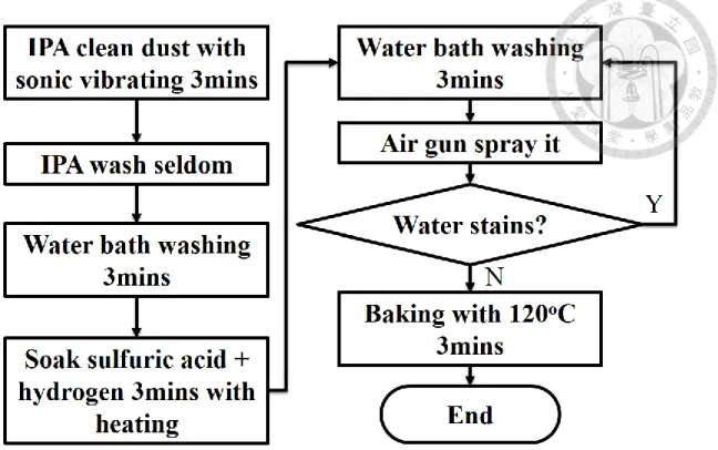
Fig. 3-1 Flow chart for cleaning wafer. ... 8
Fig. 3-2 Schematic of SU-8 thin film. ... 9
Fig. 3-3 Flow chart for SU-8 thin film. ... 9
Fig. 3-4 Soft baking process. ... 10
Fig. 3-5 Sweat pore design on 4-inch wafer. ... 11
Fig. 3-6 SU-8 fail thin film. ... 12
Fig. 3-7 Fabricated SU-8 films with sweat pores. ... 13
Fig. 3-8 Wet etching process to remove the copper sacrificial layer. ... 13
Fig. 3-9 Fabricated artificial stratum corneum. ... 14
Fig. 3-10 Flow chart for fabricated SU-8 thin film without sweat pores. ... 14
Fig. 3-11 Flow chart for gelatin film. ... 15
Fig. 3-12 Heat and stir gelatin solution. ... 16
Fig. 3-13 Flow chart and schematic for completing phantom. ... 17
Fig. 4-1 Phantom thickness measurement. ... 18
Fig. 4-2 OM sweat pores observation. ... 19
Fig. 4-3 Compression test on phantom. ... 20
Fig. 4-4 Impedance measurement on phantom. ... 21
Fig. 4-5 Impedance mesurment on dry condition... 22
Fig. 4-6 Impedance measurement in wet condition. ... 23
Fig. 5-1 Side view of device: two legs with vector loop. ... 25
Fig. 5-2 Fall prevention on mechanism moving diagram. ... 25
Fig. 5-3 Exoskeleton mechanism. ... 26
Fig. 5-5 Calibration system. ... 29
Fig. 5-6 Stop system. ... 29
Fig. 5-7 Graphical user interface. ... 30
Fig. 5-8 Mode 1 control block diagram. ... 31
Fig. 5-9 Schematic of system plant. ... 33
Fig. 5-10 Mode 2 control block diagram. ... 38
Fig. 5-11 Mode 3 control block diagram. ... 41
Fig. 5-12 Signal flow deviation for physical concept. ... 41
Fig. 5-13 Simplified signal flow. ... 42
Fig. 5-14 Second simplified signal flow. ... 42
Fig. 5-15 Third simplify signal flow. ... 43
Fig. 5-16 Complete signal flow. ... 43
Fig. 6-1 Hip angle rotation command within a gait. ... 46
Fig. 6-2 Root locus diagram for mode1 plant. ... 48
Fig. 6-3 Step response for P control mode 1. ... 49
Fig. 6-4 Step response for PID control mode 1. ... 50
Fig. 6-5 Root locus diagram for mode 2 plant. ... 51
Fig. 6-6 Step response for first P control mode 2. ... 52
Fig. 6-7 Step response for second P control mode 2. ... 52
Fig. 6-8 Step response for first PID control mode 2. ... 53
Fig. 6-9 Step response for second PID control mode 2. ... 54
Fig. 6-10 Root locus diagram for mode 3 plant. ... 55
Fig. 6-11 Step response for P control mode 3. ... 55
Fig. 6-12 Step response for PID control mode 3. ... 56
Fig. 7-1 Motor speed and PWM duty transformation. ... 57
Fig. 7-2 Zero calibration flow chart. ... 58
Fig. 7-3 Main program flow chart. ... 59
Fig. 7-4 Mode 1 adaptive IXR testing result. ... 60
Fig. 7-5 Mode 1 static IXR testing result. ... 61
Fig. 7-6 Mode 2 control parameter group A testing result. ... 63
Fig. 7-7 Mode 2 control parameter group B testing result. ... 63
Fig. 7-8 Mode 3 testing result. ... 64
Fig. 7-9 Right leg test without human in auto walking mode. ... 66
Fig. 7-10 Left leg test without human in auto walking mode. ... 66
Fig. 7-11 Two-leg rotation result. ... 67
Fig. 7-12 Speed up testing. ... 68
Fig. 7-13 Free motor at auto walking mode. ... 69
Fig. 7-14 Loading test at auto walking mode. ... 70
Fig. 7-15 Gait command tracking result. ... 72
Fig. 8-1 Package at back plate. ... 73
Fig. 8-2 Power consumption within gait cycle. ... 74
Fig. 8-3 wearing result for angle time relation. ... 75
Fig. 8-4 Normal human free walking gait. ... 76
Fig. 8-5 Normal human gait assisted by exoskeleton. ... 76
Fig. 8-6 wearing result for gait cycle representation. ... 77
Fig. 8-7 Normal human with barrier. ... 78
Fig. 8-8 physically challenged human wearing for angle time relation. ... 79
Fig. 8-9 physically challenged human free walking gait... 80
Fig. 8-10 physically challenged human gait assisted by exoskeleton. ... 80
Fig. 8-11 physically challenged human wearing for gait cycle representation. ... 81
Fig. 8-12 physically challenged human wearing for gait cycle comparison. ... 82
LIST OF TABLES
Table 4-1 Averaged film thickness. ... 19
Table 4-2 Morphology testing result. ... 20
Table 4-3 Modulus of elasticity. ... 21
Table 4-4 Electrical circuit model fitting dry measuring result. ... 23
Table 5-1 Known parameters. ... 32
Chapter 1 Introduction
1.1 Background and motivation
Since the Berkeley Lower Extremity Exoskeleton (BLEEX) [1] was proposed, the exoskeleton research has become a trend around world. An exoskeleton is designed for strengthening normal human’s behavior. On the other hand, helping weak human to become normal is also a way to strengthen human ability. We focus on lower limb assistance as a mission to allow people to enjoy the freedom of walking. Lower limb problem may happen on human who suffers from serious injury such as car crash or falling. It would also happen on human whose muscle degrades due to aging. The fact that people with degraded muscles are reluctant to exercise makes the lower limb problem even worse. Accordingly, exoskeleton is aimed to modify and to facilitate human locomotion in a strengthened manner.
1.2 Literature review 1.2.1 Skin phantom calibration
The challenge of EEG capturing is that brain signal is weak. How to make reliable measurement is a difficult problem. For resolving this problem, we should make a testing platform, which is repeatable for testing EEG measurement. Using human subject to test EEG recoding has problem that human would not easy to show repeatable brain signal. In addition, using large human subjects to test EEG can be costly. On the other hand, artificial skin phantom can be a reusable test platform. Phantom testing on EEG is promising [2].
In general, artificial skin phantoms can be categorized into two groups, the physical skin phantom and the tissue-engineered skin model. The former is designed to analogize the practical physical condition of a human skin during in vitro experiments, and the latter focuses on the biological relevance of a human skin [3]. Various phantoms of this physical type have been developed for analogizing the mechanical or electrical properties of real human skin. For instance, a gelatin-based model was developed to analogize the mechanical conditions of human skin under reentry shots [4] while a silicone-based model doped with graphite was proposed to analogize the electrical conditions of a human skin [5].
The physical skin phantoms are suitable for our design because we focus on the physical properties of a human skin for the applications of EEG testing and calibration.
The goal of this research is to develop an artificial skin phantom with mechanical and electrical properties of the phantom are close to those of real human skins. The morphology of the phantom is also similar to that of a real human skin. In addition, the artificial skin phantom is prepared for testing EEG device to calibrate noise.
1.2.2 Overview of walking assist device
Many lower limb exoskeletons have been proposed to assist human walking.
Sankai et al. develop hybrid assistive limb-5 (HAL-5) to aid human whose muscle degenerated. HAL-5 have two main control system. One is measuring EMG to know whether human want to walk or not. The other is storing walking patterns for individual user [6]. Long et al. used active disturbance rejection control strategy to track human gait trajectory on a lower limb exoskeleton made of carbon fiber for rehabilitation. They also used an extended-state observer to estimate and then suppress the disturbance by applying a control action [7]. Ollinger et al. developed an admittance control model to
estimate the human-assistive effect on Honda stride management assist (SMA) device.
They also discussed robust stability on their control system [8].
Nagarajan et al. establish control strategy on Honda SMA device, which is based on modify the dynamic response of human limbs. By increasing the mechanical admittance, human lower limbs are more responsive to any muscle torque generated by user [9]. Liu et al. construct variable stiffness actuator, which can modulate output stiffness by changing the effective length of a bending bar. Their results show that the controller can achieve the desired performance in reference tracking [10].
Chen et al. designed a portable knee-ankle-foot robot to help stroke patients. They developed control strategies on gait phase and applied appropriate assistive force at corresponding gait phases [11]. Oh et al. propose various assistive control. Detecting walking motion phases by switching control algorithms, system would pick up appropriate control framework to handle plant [12]. Achili et al. proposed a stable adaptive observer. It can be applied to any other nonlinear system of similar dynamics [13]. Giovacchini et al. presented a lightweight carbon fiber active orthosis, whose weight is 4.2 kg, to assist hip rotation. User could walk with this orthosis without feeling hindered [14]. Asbeck et al. proposed a soft exosuit for portable hip assistance.
Their soft design would not restrict hip ab- and adduction direction or rotation about leg axis [15]. Ouyang et al. developed a power unit for exoskeleton robot, a compact hydraulic power unit powered by an internal combustion engine (CHPU). The CHPU can provide 1.5 kW hydraulic power and 100 W electric power, which can meet the requirement for exoskeleton robots [16]. Selinger et al. designed myoelectric control, which can adapt the timing and magnitude of electrical power generation for an energy harvesting exoskeleton [17]. Hussain et al. proposed an adaptive seamless assist-as-needed (AAN) control, which is for the robotic gait training. They found that
the robotic orthosis is capable of guiding human limbs on reference trajectories [18].
Vouga et al. presented a lower-limb exoskeleton controlled by brain for rhesus macaque.
They demonstrated the feasibility of a brain-controlled lower-limb exoskeleton [19].
Zhang et al. presented a rehabilitation exoskeleton, which can undergo walk training on patient’s individual walking habit. Their exoskeleton can evaluate patient’s rehabilitation status in real time by providing necessary torques on the dyskinetic leg [20]. Jin et al. used adaptive fuzzy sliding mode control on a lower limb exoskeleton.
Their wearer feels more comfortable to move the swing leg [21, 22]. Long et al.
proposed passive mode and active mode, respectively, on a lower limb rehabilitation exoskeleton for unilateral lower limb movement disorders patient. Exoskeleton in the former case would copy healthy gait trajectory. The latter would modify healthy gait trajectory and help to strengthen the unhealthy limb [23]. Zhu et al. presented an unidirectional variable stiffness hydraulic actuator for loading carrying knee exoskeleton. Their results show that the system has good performance on stiffness regulation and joint torque control [24].
We want to develop a compact walking-assistive device on lower limb. Our exoskeleton should let user feel comfortable as receiving the help form the power unit.
Chapter 2 Design of artificial skin phantom
2.1 Real human skin properties
Normal human skin would contain three layers, stratum corneum, epidermis, and dermis. We design our skin phantom by only considering the stratum corneum and epidermis. The reason why we skip dermis is as following. First, the electrical resistivity of the stratum corneum and the epidermis is larger than that of the dermis [25].
Therefore, we can skip the dermis due to its small impedance. Secondly, there are many cells in dermis such as nerves and bloods cells [26]. There is no need to implement EEG calibration circuit with these cells to eliminate static noise. Therefore, we would design a two-layer structure, which includes stratum corneum and epidermis.
We are curious about human sweating situation on EEG calibration. Human sweating may affect the resistivity on EEG electrode. Then we consider sweat pores and sweat ducts structure within our phantom design.
2.2 Selection of Phantom Material
We choose SU-8 photoresist and gelatin as materials for making stratum corneum and epidermis, respectively. Our desired stratum corneum thickness should be 10~40 μm [25]. Our desired epidermis thickness should be 70~100 μm [27]. The resistivity of human skin is a function of frequency, which is 107 Ωm in the frequency range from 1Hz to 1kHz and 104 Ωm at the frequnecy of 1MHz [25]. The modulus of elasticity of human skin has a larger variation measured by different researchers and a reasonable range is from 100 kPa to 20 MPa [28~30]. The density of the sweat pores is in the range from 200 pics/cm2 to 700 pics/cm2, and the diameter of the sweat pores fall in the range from 20 to 50 μm. Values of both density and diameter of sweat pores vary for different
parts of human bodies [31]. We choose to simulate palm sweat pore density due to its density is highlest than other parts.
Fig. 2-1 Skin phantom design structure.
SU-8 works as insulators [32] in terms of electrical properties, which is same as stratum corneum properties. The SU-8 film can be fabricated from 10 to 40μm [33], which is analogous to stratum corneum thickness. Due to its photoresist property, the SU-8 can make tiny sweat pore and dense pores density with micromachining technology.
Gelatin is a natural material extracted from skin, tendons, ligaments, or bones of animals. Gelatin powder can be dissolved in hot water to form a film. The hydrogen bonds inside the gelatin solution would make the solidified film elastic, which can analogize the mechanical properties of human skin. In addition, the gelatin electrical properties can be changed by mixing conductive elements such as acetic acid, graphene, or lithium ion, into gelatin solution [34~36]. Hence, gelatin can provide different electrical properties for simulating different human skin conditions.
Chapter 3 Phantom fabrication
Our skin phantom imitates human skin and thus contains two layers, artificial stratum and artificial epidermis. It also possesses sweat pores and sweat ducts. We choose SU-8 2025 negative type photoresist and gelatin as the phantom materials. These two materials are appropriate to simulate real human skin and are easy to make sweat pores and sweat ducts with microfabrication and laser ablation.
We divide the whole process into three main steps. The first is to make artificial stratum corneum with sweat pores by using micromachining techniques. The second step is to make artificial epidermis with cross-linked gelatin. At this step, we combine stratum corneum and epidermis together. Finally, we will use laser ablation technique to make sweat ducts.
3.1 Artificial stratum corneum with sweat pores
Microfabrication process includes many steps such as electron beam evaporation, spin coating, photolithography and wet etching. Some steps, especially spin coating, require good adhesion of negative photoresist on the substrate. In this work, polished 4-inch oxidized silicon wafer is used as the substrate.
The wafer-cleaning process is depicted in Fig. 3-1. First, the silicon wafer is immersed in isopropyl alcohol (IPA) under sonication to remove macro particles. Then the silicon wafer is rinsed with de-ionized (DI) water. We use heated solution of sulfuric acid and hydrogen peroxide to remove possible polymer residues and then rinse the wafer with DI water again. The wafer is then dried by using air gun, followed by baking at 120oC for 3 minutes.
Fig. 3-1 Flow chart for cleaning wafer.
The process to fabricate artificial stratum corneum is depicted in Figs. 3-2 and 3-3, respectively. Firstly, a chromium adhesion layer of 10 nm in thickness is deposited on the cleaned substrate by using electron beam evaporation. Then, the copper sacrificial layer of 100 nm in thickness is deposited by using the electron beam evaporation. A layer of SU-8 2025 is spin-coated on the copper layer. The spin rate is firstly kept at 500 rpm for 250 sec and then ramped up to 3000 rpm that is maintained for 300 sec. The obtained SU-8 thickness is 25 μm. It is baked at 65oC for 6 minutes and then at 95oC for 12 minutes later.
Fig. 3-2 Schematic of SU-8 thin film.
Fig. 3-3 Flow chart for SU-8 thin film.
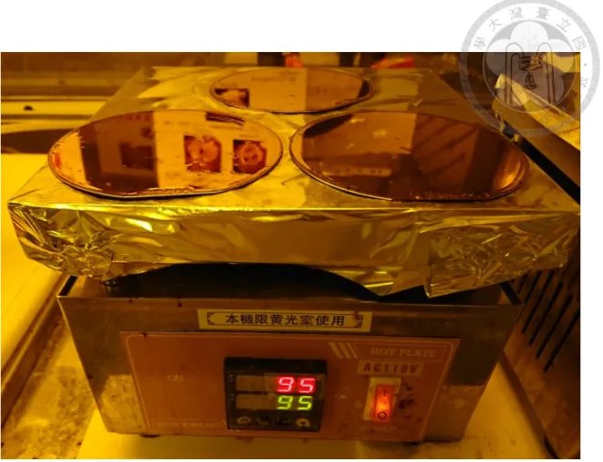
Following the datasheet of SU-8 [33], soft baking should be conducted after spin coating. As shown in Fig. 3-4, the soft bake was conducted on hot plate at 65oC for 6 minutes and then 95oC for 12 minutes. Then, the wafer is cooled down at room temperature.
Fig. 3-4 Soft baking process.
Photolithography process is the main step to pattern sweat pore onto SU-8 2025.
We use the mask shown in Fig. 3-5. The mask has opaque dot patterns, which define the sweat pores, as the portion (a) in figure. The dot diameter and density is 20 μm and 620 dots/cm2, respectively. The mask is separated into 4 parts by two 1 mm-wide straight lines, as the portion (b) in figure. This design allows etchant remove the sacrificial layer quickly [37].
Fig. 3-5 Sweat pore design on 4-inch wafer.
We use EVG 620 top-side mask aligner to exposure SU-8. We choose soft contact with 80 μm gap between the mask and wafer. The exposure energy and time are 10.7 mW/cm2 and 240 seconds, respectively. The post-exposure bake is conducted at 65oC for 4 minutes and then 95oC 12 minutes. It eliminates the standing wave effect of the exposure light.
We choose acetone as the developer. The under-exposed SU-8 (60 sec) causes poor adhesion of the film on the substrate. Therefore, wrinkles are observed after development in acetone, as shown in Fig. 3-6. The wrinkled SU-8 is not suitable for making the skin phantom. It can be removed by etching out the underneath copper using the solution of sulfuric acid and hydrogen peroxide.
Fig. 3-6 SU-8 fail thin film.
For longer exposure time such as 120 sec, the SU-8 thin film becomes very brittle after development. Drying the film using air gun would break the film into many fragments. Therefore, we exploit the high volatility of acetone and allow the wafer to dry out spontaneously after development. After development, the hard baking was conducted in oven at 120oC for 30 minutes. The fabricated SU-8 film with sweat pores is shown in Fig. 3-7.
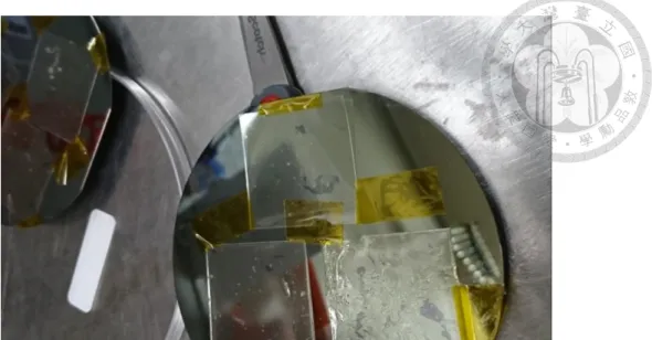
Fig. 3-7 Fabricated SU-8 films with sweat pores.
Fig. 3-8 Wet etching process to remove the copper sacrificial layer.
Fig. 3-9 Fabricated artificial stratum corneum.
Ferric chloride solution is used to remove the copper sacrificial layer, as shown in Fig. 3-8. The fabricated artificial stratum corneum is shown in Fig. 3-9. We also make an SU-8 thin film without sweat pores for comparison. The flow chart is shown in Fig.
3-10.
Fig. 3-10 Flow chart for fabricated SU-8 thin film without sweat pores.
3.2 Combination of stratum corneum and epidermis
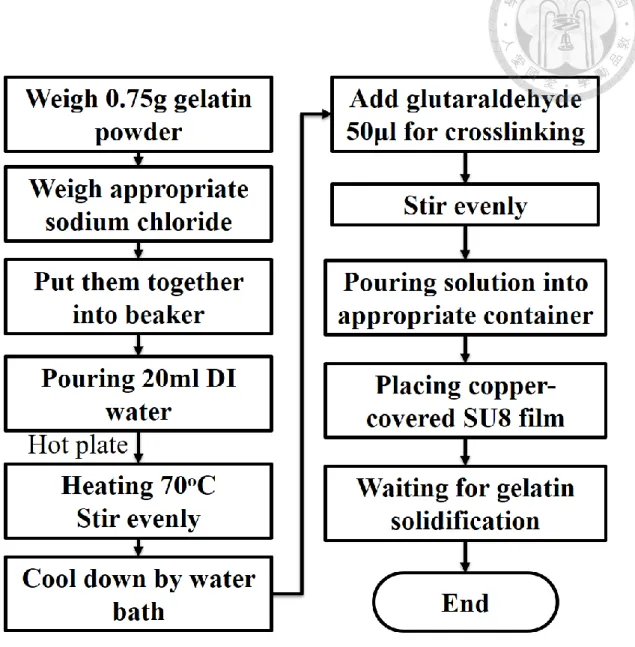
Fig. 3-11 Flow chart for gelatin film.
The process to assemble artificial stratum corneum and epidermis is shown in Fig.
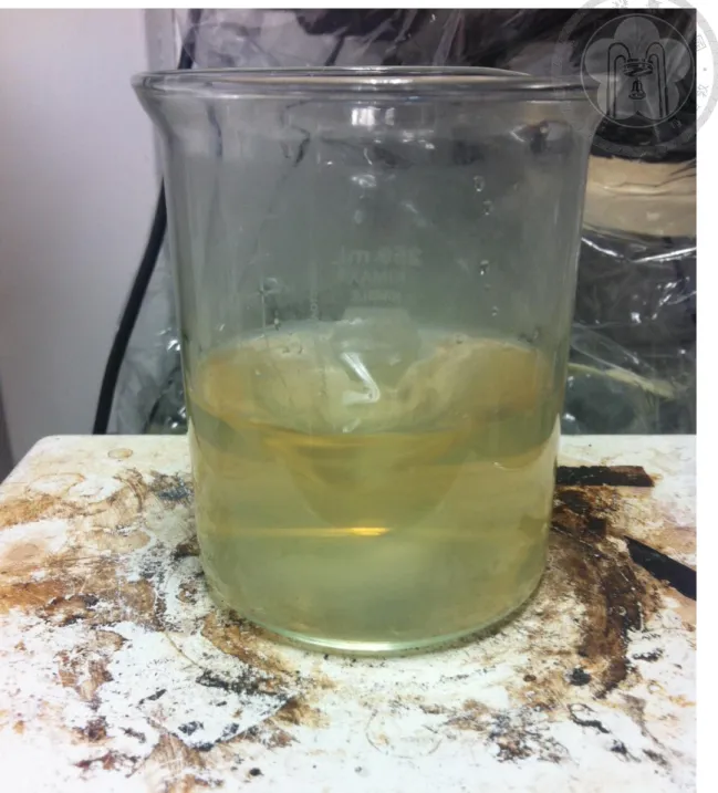
3-11. First, we make gelatin-based epidermis. In process, we mix gelatin powder with sodium chloride to make the salt content of 0 %, 0.5 % and 1.4 %, respectively of total weight. The corresponding salt weight is 0, 0.1, and 0.3 g, respectively. Modulating salt content is to simulate different human skin conditions. The mixed powers are dissolved in 20 mL DI water at 70oC, as shown in Fig. 3-12.
Fig. 3-12 Heat and stir gelatin solution.
After cooling down the mixture, we gently add 50 μL glutaraldehyde by using pipet. Glutaraldehyde can help gelatin particle to form crosslinks. It should be noted that glutaraldehyde has cytotoxicity [38]. We then stir the solution until the glutaraldehyde is well mixed. To mold gelatin into a film as artificial epidermis, we pour the solution into an appropriate container. The container height should be perfectly horizontal so that our
epidermis can have uniform thickness. We then put copper-coated stratum corneum onto the gelatin and let the gelatin solution naturally dry out.
We found that higher salt content makes softer artificial epidermis. The reason is that salt particle would obstruct gelatin particle from crosslinking. We can apply UV light exposure to enhance gelatin crosslinking for increasing the Young’s modulus of the artificial epidermis.
3.3 Fabricating artificial sweat ducts
Fig. 3-13 Flow chart and schematic for completing phantom.
The process of make sweat ducts in the phantom is shown in Fig. 3-13. We use M-360 laser cutting machine as our laser ablation platform. The laser power of M-360 is set at 10%. Because there is copper coating on the stratum corneum to absorb laser power, only the gelatin exposed by the SU-8 opening will be ablated. After making the sweat ducts, we remove the top copper mask by using chloride solution.
Chapter 4 Phantom properties test
4.1 Morphology tests
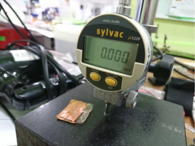
The morphology test is to verify the phantom thickness and the sweat pore size. To imitate normal human skin, the phantom thickness should be close to 100 μm. The diameter of the fabricated sweat pores should be close to 20 μm.
We use the μ229 thin film measurement instrument, from Sylvac, to determine the phantom thickness, as shown in Fig. 4-1. The results are listed in Table 4-1. Their standard deviations, with the salt content form low to high, are 14, 7 and 14.4 μm, respectively.
Fig. 4-1 Phantom thickness measurement.
Table 4-1 Averaged film thickness.
Phantom salt content (%) Average thickness (μm)
0 142
0.5 137
1.4 153
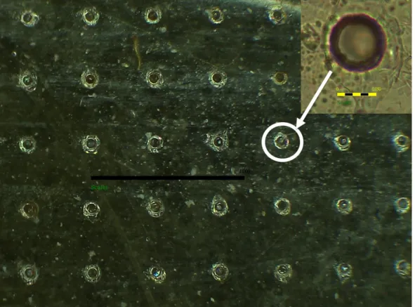
We use optical microscopy (OM) to characterize the density and diameter of the fabricated sweat pores. We use low magnification to check the sweat array, as shown in Fig. 4-2. The center-to-center distance adjacent sweat pores is 400 μm. There are 25 sweat pores in the field size of 4 mm2. Therefore, the obtained sweat pore density is 625 pores/cm2, close to that on human palm. Under large magnification of the microscope, it is confirmed that the diameter of the fabricated sweat pores is 20 μm. Table 4-2 shows all morphology measuring result and real human skin properties for comparison.
Fig. 4-2 OM sweat pores observation. The inset shows a single sweat pore.
Table 4-2 Morphology testing result.
Measurement Specification [25,31] Result
Thickness 80~140μm Average 142μm for no salt
Sweat pore density 200~700 pics/cm2 Around 625 pics/cm2
Sweat pore diameter 20~50μm Around 20μm
4.2 Mechanical tests
We use compression test to measure modulus of elasticity. We choose Kyowa full-scale 50 N load cell to characterize the fabricated phantom. We use precision stage, SHOT204, and load cell to implement stress and strain relation, as shown in Fig. 4-3. In the test, the load cell compresses the phantom at 100 μm/s. The contact radius of the load cell on the phantom is 2 mm. The size of the phantom under test is 10 mm x 5 mm.
The obtained modulus of elasticity of the phantoms of different salt contents is shown in Table 4-3. These results are in good agreement with the test on real human skin [28~30].
Fig. 4-3 Compression test on phantom.
Table 4-3 Modulus of elasticity.
Phantom salt content (%) Modulus of elasticity (MPa)
0 1.608
0.5 1.135
1.4 1.661
4.3 Electrical tests
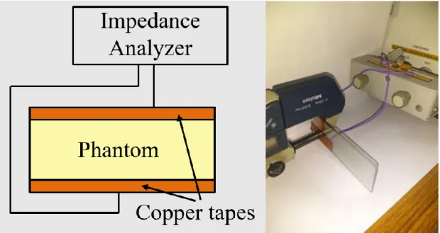
The objective to design this phantom is to calibrate static noise from EEG measuring device. This static noise is mainly coming from electrical circuit. To eliminate this electrical noise, we should measure impedance of our phantom. By this measurement, we can constructed impedance circuit with phantom at EEG noise calibration.
Fig. 4-4 Impedance measurement on phantom.
We test the impedance by using Keysight E4990A, as shown in Fig. 4-4. We found that copper foil tape causes lower contact resistance than copper tape does. The measured impedance is shown in Fig. 4-5. We use resistivity, instead of impedance, to discuss the material properties so that the dimension effect can be ignored. The obtained resistivity is up to 107 Ωm at 1~10 kHz and drops to 104 Ωm at 1 MHz. By comparing to the literature [25], we can conclude that our skin phantom fit to human skin impedance property at dry condition.
Fig. 4-5 Impedance mesurment on dry condition.
We then soak our samples with phosphate-buffered saline (PBS) to simulate wet condition. To make sure test sample water content, we measure wet sample. The measured impedance in wet condition is shown in Fig. 4-6. The wet phantoms are more conductive than real human skin. This is because the human skin has cell membranes
that impede water flow and thus the electron transports. Based on equivalent circuit on epidermis [39, 40], we fit our skin phantom dry condition result with parallel resistance and capacitor circuit model with ADS circuit design software. The results are shown in Table 4-4.
Fig. 4-6 Impedance measurement in wet condition.
Table 4-4 Electrical circuit model fitting dry measuring result.
Salt content (%) Resistance (MΩ) Capacitor (pF)
0 97.65 50.8
0.5 31.27 40.5
1.4 17.98 34.5
Chapter 5 Structure and control theory
In this chapter, we would introduce structure of our assistive device. Our structure is designed to cover human body from hip to knee. After introducing mechanism, we will introduce the electronics of our system such as motor and its related circuitry. Then we will construct control model based on ESCON module. Different control modes will be compared.
5.1 Exoskeleton mechanism
Our exoskeleton is designed to have two degrees of freedom (DOF) on hip joint, which is the rotation of flexion/extension and adduction/abduction, respectively. We remove one DOF to let pelvic joint perform self-rotation about thigh. This DOF is not the most important part on assist walking, so we simplify this DOF on mechanism design.
For exoskeleton motor axis and back plate axis, there are two axes intersecting at the center of human hip joint. Motor is driving the rotation of flexion/extension. This design would let human motion more comfortable. They would feel exoskeleton like extension of their body. Based on gait cycle, we define human hip and knee angle rotating range. Then we design a cylinder sliding mechanism, which can fix human leg moving range properly.
Fig. 5-1 shows the side view of exoskeleton for right leg and left leg, respectively.
Heng-Chia Hsu previously used vector loop method to find actual size of each mechanism part [41]. The black vectors and gray vectors would construct two different vector loops. With these two loops and human joint information within gait cycle, they use kinematics equation to determine all dimensions.
Fig. 5-1 Side view of device: two legs with vector loop.
In Fig. 5-1, the cylinder in the slot moves up and down during walking. We measure the bearing connecting the motor axis and the pin in the slot, as shown in Fig.
5-2. Although the knee can not reach 60o flexion of the human knee joint limit, 50o moving range is sufficient for walk assistance. This fixed cylinder can restrict human thigh rotation. We define this limitation as fall prevention function in our exoskeleton mechanism.
Fig. 5-2 Fall prevention on mechanism moving diagram.
Fig. 5-3 Exoskeleton mechanism. The left inlet is the front view, and the right is the side view.
The whole exoskeleton mechanism is shown in Fig. 5-3. The weight is 2.3 kg without motor. For user’s comfort, we use touch fasteners sticky to fix human knee upper and lower parts. Then we use travel package fixing belt to tie human shoulder and waist with the exoskeleton, to avoid total mechanism fall down from human body.
5.2 Circuit and servo amplifier 5.2.1 Motor chosen
We choose brushless DC motor (BLDC motor) to drive the exoskeleton. BLDC motor is generally used for high positioning accuracy. Its brushless feature can avoid sparks and brush friction loss so that BLDC motor can save energy and pursuit high
efficiency.
The basic concept of BLDC motor is that replacing the carbon brush with electronics in a motor. With the electronics and control for each switch, this non-mechanical contact system can change the direction as carbon brush does. BLDC motor has the following advantages. First, it runs quietly and is suitable in some quiet places such as hospitals and schools. Second, BLDC does not generate any spark and thus can use in some flammable and explosive places. Third, BLDC is more durable because it uses controller instead of the carbon brush.
BLDC motor has three phases and a Hall position sensor so the motor commutation accurate rotor position detection accuracy is not affected by the motor speed. It does not require additional rotor position detection circuit hardware. We install the gearbox to ensure that motor have ability to supply sufficient torque to assist the human body.
5.2.2 Servo amplifier
To drive BLDC motor, we need to know rotor position by Hall sensors. We then need to input correct three phases driving signal and enough power to drive the motor.
We choose the BLDC motor, MAXON EC 60 flat [42], with gearbox as our system power unit. Its corresponding servo amplifier is ESCON module 50/5 [42].
To setup the motor, we should prescribe the motor phase. Our motor have already inserted encoder; we should set encoder information in ESCON studio to make sure that the encoder is working. To drive the motor by using ESCON, the digital I/O and analog input can be set as a function to enable or disable motor driving, to accept PWM duty from controller, and to determine the motor driving direction. For capturing data, ESCON can set analog output pin to read motor speed and current data.
ESCON can operate three different modes to control motor. In Mode 1, ESCON
acts as a voltage amplifier. ESCON can do IXR compensation in mode 1 and 2. IXR compensation is to stabilize voltage during motor rotation. Parameters of IXR compensation can be chosen as static or dynamic in mode 1. In mode 2, motor speed is controlled in closed loop using feedback from the encoder. In mode 3, motor current is controlled in a closed loop, which is useful for torque control. We compare these three modes control effect for our exoskeleton system. We then choose the proper mode to control the exoskeleton.
5.2.3 Controller circuit
We separate our electrical system into three sub-systems: action system, calibration system; stop system and graphical user interface. The action system is for moving exoskeleton. The calibration system is for calibrating the zero position. The stop system is to help user stop exoskeleton in emergency. Graphical user interface is for user to see actuation angles and calibration state.
When we need to move the exoskeleton, we design a button for user to control.
The button delivers signal of “walking”. Then National Instrument (NI) Myrio [43]
captures the feedback signal of the encoder and calculates PID algorithm. The signal that after PID calculation will pass from NI Myrio to ESCON 50/5 motor driver as PWM signal. Finally, ESCON 50/5 would control MAXON EC60 flat motor to achieve our expected gait cycle. Fig. 5-4 illustrates this process.
Encoder
Fig. 5-4 Action system structure.
We also place hall sensor at point B in Fig. 5-5. This component can make program to identify zero rotation, which can provide information to help user stand. This is important as if we lose the real zero position, the encoder signal would be not correct.
Producing a wrong signal to the algorithm will make a wrong output signal.
Fig. 5-5 Calibration system.
To avoid motor rotation over the range of gait cycle, we make two limit switches on the sliding boundary, as shown in Fig. 5-6. When stance state occurs, the cylinder will hit limit switch. Then the controller will command the driver to stop motor to prevent user from injury.
Fig. 5-6 Stop system.
B
The graphic user interface is shown in Fig. 5-7. With this interface, user can know the motion of the exoskeleton. The information comes from the right and left leg encoder signal. This signal is calculated with gear ratio for correspond to actual angle rotation. There are two lights placed at the upper left side of the interface. One is to tell user whether the limit switch has been triggered. An on light indicates that the corresponding leg reaches the stance state. The other light is to tell user whether the exoskeleton has been calibrated or not. This bulb lighting is a result from Hall sensor signal. When the user is standing, which is zero calibration state as we defined, the Hall sensor is triggered by strong magnetic flux. This is signal for reaching zero state, and the bulb is turned on. There is one button placed at upper right side. By pushing this button, the system will stop for emergency. Motor driving would be disabled for safety consideration. Then program would start to collect data before this button is pushed again. The data such as encoder signal, motor current and motor speed can help us analyze the system failure.
Fig. 5-7 Graphical user interface.
5.3 Motor position control theory
We consider Shannon sampling theorem for continuous-to-discrete transformation.
Our sampling rate is well designed as 1000 Hz. We consider control diagram for angle position as below. The output of this system is the actual rotation angle , which is a disturbed by human noise, . h The control block diagram is shown in Fig. 5-8. By combining human normal gait data as control command, , with left summing point, c we can get the angle error, , as a controller input. e
Fig. 5-8 Mode 1 control block diagram.
We use PID controller in this work. This controller has good stability and high reliability. Its structure is easy to implement and understood. A PID controller includes three data feedback processing system, which is proportional, integral and derivative control. Proportional control can enlarge or shrink error to track input signal, which can enlarge system over shoot. Integral control can gradually stack error, which can eliminate steady state error. However, integral control is too slow to handle instant system variation. In contrast, derivative control can estimate error variation in advance.
However, derivative control can be easily disturbed by high frequency noise. This disadvantage should be compensated by integral control.
The angle position control model would be easier to have two extra poles than common control system. To stabilize these two characteristics, we use two zeros from
PID to handle this problem. The PID controller structure yields the following two equations:
2
2
D 2 D D
P I P
e
k k k
k k T z k z
V T T T
C z z z
(1)
2
2
1 D 1 2 D p D
P P
I e
T T k T
k T z k z
T T T T
C z V
z z
(2)
Here kp, kI and k are three gains correspond to each control model. In digital D control field, it often uses TI and T to design D kI and k with sampling period T . D After deriving controller structure, we can derive plant structure. For rotation system, the mass is the moment of inertia. We estimate the system effective moment of inertia as
2
1
effective rotor gear coupling load
J J J J J
N (3)
We estimated Jload with our exoskeleton moving bar and knee part combination on Solid Works software. After obtaining Jeffective, we put a table to sort any known parameters. Some information is from MAXON datasheet [42].
Table 5-1 Known parameters.
Parameter (unit) Value
kt (Nm/A) 5.340e-2
kb (V*s/rad) 5.340e-2
R (Ω) 0.307
L (V*s/A) 1.880e-4
effective
J (kg*m2) 1.303e-4
T (s) 1.000e-3
Although the BLDC is a three-phase motor, which means it is composed of three inductance and resistance pairs. We only consider one phase in our motor electrical differential equation because the current would only pass through one phase during motor rotation. After exchanging phases, the current would pass through other inductance and resistance pairs.
v M
Loading J L
T θ
R
Fig. 5-9 Schematic of system plant.
The transfer function of angle position over voltage for one of phases for BLDC with equivalent circuit shown in Fig. 5-9. Assume that rotor, loading have effective mass moment of inertia J . The motor characteristic are two relations: k it and , where kt is motor torque constant and i is armature current. The other relation shows that back electromotive voltage Vb composition. It is the product of motor speed constant kb and angular rate . The free body diagram for rotor in Fig.
5-9 yields
(4)
where is the angular acceleration, which is considering human noise influence.
Analysis of the electric, including the back electromotive voltage , leads to
(5)
By applying current,
2
2 t
i J d k dt
, into equation (5) gives
3 2
3 2 b
t t
JL d JR d d
v k
k dt k dt dt
(6)
The Laplace transform of equation (6) is
3 2
( ) b ( )
t t
JL JR
V s s s k s s
k k
(7)
which can be rewritten as
3 2
( ) ( )
t b t
k R k k
V s s s s s
JL L JL
(8)
In control theory, standard mass damper spring system (MCK system) has second order differential equation. Its transfer function standard form is
2
2 2
2
n
n n
s s
(9)
In this standard form, there are two characteristic properties, which are natural frequency (n) and damping ratio (). These two properties play an important role in system response. Although variable of equation (8) has third order term, these properties still can be used because of our system has constants for common MCK system problem.
In our case, these two properties can be written as:
b t n
k k
JL (10)
2 n 2 b t
R R J
L k k L
(11)
Value of natural frequency and damping ratio in our system is 341rad/s and 2.393.
Sorting equation (8) with two characteristic properties, the transfer function for the motor is readily found to be
2
3 2 2
( ) 1
( ) ( ) 2
n V
b n n
G s s
V s k s s s
(12)
This transfer function is used in continuous domain. Unless we use operational amplifier circuit to control exoskeleton power unit directly, we should consider transfer function in discrete domain for digital controller such as computer or micro controller.
To discretize the transfer function for angle position over voltage, we must understand zero order hold, which is a common way in digital-to-analog conversion. Zero order hold is a mathematical model of the practical signal reconstruction. That is, it describes the effect of converting a discrete-time signal to a continuous-time signal by holding each sample value for one sample interval. To get this mathematical model, we constructed two-step functions. One is normal step function, and the other is step function with one sample interval delay. After subtracting these two functions, we get a constant within one sample interval, which means discrete signal in pre sample interval is held to present sample interval. As a result,
1 e sT 1 e sT
s s s
(13)
To obtain discrete transfer function, which is so called z domain transfer function, we should consider new system dynamics (NSD), which is the multiplication of zero order hold (equation (13)) and continuous transfer function (equation (12)).
2
4 3 2 2
( ) 1
( ) 2
sT
n
b n n
s e
NSD V s k s s s
(14)
There is a useful transformation matching table between time domain, s domain, which is continuous frequency domain, and z domain, which is digital domain [44]. To use this
table for quickly getting transformation equation representation on z domain, we must do partial fraction expansion with continuous transfer function as
2 2
2 2 2
4 1
( ) 1 1 2
( ) 2
n sT
b n n n
s e s
NSD V s k s s s s
(15)
The first and second terms can be directly transformed from s domain into z domain by applying transformation table. For the last term, it is difficult to transform because our parameter on the damping ratio is over one, which implies an over-damping system.
There is only under-damping system for table, and its component has 12 term. If we directly substitute s domain last term into transform pair, it would show imaginary term in our transfer function, which is difficult to programmable of our transfer function for control root locus design. Fortunately, this useful table also can match time domain transform to z domain transformation pair. Therefore, we can do inverse transform with last term of partial fraction expansion on s domain transfer function.
2
2
2
2 1 1
1
2 2
4 1
2
n n
n t t
n n
L s ae be
s s
(16)
where
2 2
2
2 2 1 1
2 1 n
a
(17)
2 2
2
2 2 1 1
2 1 n
b
(18)
Transferring the above time domain equation into z domain gives
2 2 1 2 1( ) 1 2
( ) b 1 n 1 nT nT
z z Tz z az bz
NSD V z k z z z
z e z e
(19)
Therefore, we found that the final simplified reduction of fractions to a common
denominator form of denominator has three poles. We define these three poles as
1 1
p (20)
2 1 2
nT
p e
(21)
2 1 3
nT
p e
(22)
After reduction of fractions to a common denominator, we can get
2 3 1 2 3
2 2
1 2 3 1 3 1 2
1 1 2
( ) * n
V
b n n n
T z p z p z p z p z p
G z
k z p z p z p a z p z p b z p z p
(23)
Then we can sort each z polynomial term on numerator. After sorting with simple linear combination, we can get the discrete transfer function on rotated angle over voltage,
GV , as
2 2
3 2
1 2 3 2 3
2
3 2
2
1 1 3 2 2
2
3 2
1 1
( ) *
2 2
2
n n
n
n
V T T
b n
n n n
T
T
n n n
G z
k z p p p z e p p z e
T b p a p z
p e c p c p z
e T a p b p
(24)
where
2 2
1 2
2 1 1
1
nT
c
(25)
2 2
2 2
2 1 1
1
nT
c
(26)
We have already known all coefficients for above equation by parametric Table 5-1 as previous described. Substituting these known parameters into equation (24) yields
2
3 2
( ) 3.742 5 1.234 4 2.490 5 ( ) ( ) 2.422 1.864 0.442
V
z e z e z e
G z
V z z z z
(27)