Type AnN/AnA/AnUCPU
Mitsubishi Programmable Controller
User's Manual
(Hardware)
Thank you for purchasing the Mitsubishi programmable controller MELSEC-A series.
Prior to use, please read both this manual and detailed manual thoroughly and familiarize yourself with the product.
MODEL ANN/A/UCPU-U(HW)E MODEL
Code 13JE82
IB(NA)-66542-I(0810)MEE
©1995 MITSUBISHI ELECTRIC CORPORATION
z SAFETY PRECAUTIONS z
(Be sure to read these instructions before use.)
Before using the product, read this and relevant manuals carefully and handle the product correctly with full attention to safety.
In this manual, z SAFETY PRECAUTIONS zare classified into 2 levels: "DANGER"
and "CAUTION".
Indicates that incorrect handling may cause hazardous conditions, resulting in death or severe injury.
Indicates that incorrect handling may cause hazardous conditions, resulting in minor or moderate injury and/or property damage.
Under some circumstances, failure to observe the CAUTION level instructions may also lead to serious results.
Be sure to observe the instructions of both levels to ensure the safety.
Please keep this manual in a safe place for future reference and also pass this manual on to the end user.
[DESIGN PRECAUTIONS]
DANGER
z Create a safety circuit outside the PLC to ensure the whole system will operate safely even if an external power failure or a PLC failure occurs.
Otherwise, incorrect output or malfunction may cause an accident.
(1) For an emergency stop circuit, protection circuit and interlock circuit that is designed for incompatible actions such as forward/reverse rotation or for damage prevention such as the upper/lower limit setting in positioning, any of them must be created outside the PLC.
DANGER
CAUTION
[DESIGN PRECAUTIONS]
DANGER
(2) When the PLC detects the following error conditions, it stops the operation and turn off all the outputs.
y The overcurrent protection device or overvoltage protection device of the power supply module is activated.
y The PLC CPU detects an error such as a watchdog timer error by the self-diagnostics function.
In the case of an error of a part such as an I/O control part that cannot be detected by the PLC CPU, all the outputs may turn on. In order to make all machines operate safely in such a case, set up a fail-safe circuit or a specific mechanism outside the PLC.
Refer to "LOADING AND INSTALLATION" in this manual for example fail safe circuits.
(3) Depending on the failure of the output module’s relay or transistor, the output status may remain ON or OFF incorrectly. For output signals that may lead to a serious accident, create an external monitoring circuit.
y If load current more than the rating or overcurrent due to a short circuit in the load has flowed in the output module for a long time, it may cause a fire and smoke. Provide an external safety device such as a fuse.
y Design a circuit so that the external power will be supplied after power-up of the PLC.
Activating the external power supply prior to the PLC may result in an accident due to incorrect output or malfunction.
y For the operation status of each station at a communication error in data link, refer to the respective data link manual.
The communication error may result in an accident due to incorrect
output or malfunction.
[DESIGN PRECAUTIONS]
DANGER
z When controlling a running PLC (data modification) by connecting a peripheral device to the CPU module or a PC to a special function module, create an interlock circuit on sequence programs so that the whole system functions safely all the time.
Also, before performing any other controls (e.g. program modification, operating status change (status control)), read the manual carefully and ensure the safety.
In these controls, especially the one from an external device to a PLC in a remote location, some PLC side problem may not be resolved immediately due to failure of data communications.
To prevent this, create an interlock circuit on sequence programs and establish corrective procedures for communication failure between the external device and the PLC CPU.
z When setting up the system, do not allow any empty slot on the base unit.
If any slot is left empty, be sure to use a blank cover (AG60) or a dummy module (AG62) for it.
When using the extension base unit, A52B, A55B or A58B, attach the included dustproof cover to the module in slot 0.
Otherwise, internal parts of the module may be flied in the short circuit test or when an overcurrent or overvoltage is accidentally applied to external I/O section.
CAUTION
z Do not install the control lines or communication cables together with the main circuit or power lines, or bring them close to each other.
Keep a distance of 100mm (3.94inch) or more between them.
Failure to do so may cause malfunctions due to noise.
z When an output module is used to control the lamp load, heater, solenoid valve, etc., a large current (ten times larger than the normal one) may flow at the time that the output status changes from OFF to ON. Take some
preventive measures such as replacing the output module with the one of a
suitable current rating.
[INSTALLATION PRECAUTIONS]
CAUTION
z Use the PLC under the environment specified in the user’s manual.
Otherwise, it may cause electric shocks, fires, malfunctions, product deterioration or damage.
z Hold down the module loading lever at the module bottom, and securely insert the module fixing latch into the fixing hole in the base unit.
Incorrect loading of the module can cause a malfunction, failure or drop.
When using the PLC in the environment of much vibration, tighten the module with a screw.
Tighten the screw in the specified torque range. Undertightening can cause a drop, short circuit or malfunction. Overtightening can cause a drop, short circuit or malfunction due to damage to the screw or module.
z Connect the extension cable to the connector of the base unit or module.
Check the cable for incomplete connection after connecting it.
Poor electrical contact may cause incorrect inputs and/or outputs.
z Correctly connect the memory cassette installation connector to the memory cassette. After installation, be sure that the connection is not loose. A poor connection could cause an operation failure.
z Be sure to shut off all phases of the external power supply used by the system before mounting or removing the module. Failure to do so may damage the module.
z Do not directly touch the conductive part or electronic components of the module.
Doing so may cause malfunctions or a failure of the module.
[WIRING PRECAUTIONS]
DANGER
z Be sure to shut off all phases of the external power supply used by the system before wiring.
Failure to do so may result in an electric shock or damage of the product.
z Before energizing and operating the system after wiring, be sure to attach the terminal cover supplied with the product.
Failure to do so may cause an electric shock.
CAUTION
z Always ground the FG and LG terminals to the protective ground conductor.
Failure to do so may cause an electric shock or malfunctions.
z Wire the module correctly after confirming the rated voltage and terminal layout.
Connecting a power supply of a different voltage rating or incorrect wiring may cause a fire or failure.
z Do not connect multiple power supply modules to one module in parallel.
The power supply modules may be heated, resulting in a fire or failure.
z Press, crimp or properly solder the connector for external connection with the specified tool.
Incomplete connection may cause a short circuit, fire or malfunctions.
z Tighten terminal screws within the specified torque range. If the screw is too loose, it may cause a short circuit, fire or malfunctions.
If too tight, it may damage the screw and/or the module, resulting in a short circuit or malfunctions.
z Carefully prevent foreign matter such as dust or wire chips from entering the module.
Failure to do so may cause a fire, failure or malfunctions.
z Install our PLC in a control panel for use.
Wire the main power supply to the power supply module installed in a control panel through a distribution terminal block.
Furthermore, the wiring and replacement of a power supply module have to be performed by a maintenance worker who acquainted with shock protection.
(For the wiring methods, refer to Type A1N/A2N(S1)/A3NCPU User’s Manual.)
[STARTUP AND MAINTENANCE PRECAUTIONS]
DANGER
z Do not touch any terminal during power distribution.
Doing so may cause an electric shock.
z Properly connect batteries. Do not charge, disassemble, heat or throw them into the fire and do not make them short-circuited and soldered. Incorrect battery handling may cause personal injuries or a fire due to exothermic heat, burst and/or ignition.
z Be sure to shut off all phases of the external power supply used by the system before cleaning or retightening the terminal screws or module mounting
screws.
Failure to do so may result in an electric shock.
If they are too loose, it may cause a short circuit or malfunctions.
If too tight, it may cause damage to the screws and/or module, resulting in an accidental drop of the module, short circuit or malfunctions.
CAUTION
z When performing online operations (especially, program modification, forced output or operating status change) by connecting a peripheral device to the running CPU module, read the manual carefully and ensure the safety.
Incorrect operation will cause mechanical damage or accidents.
z Do not disassemble or modify each of modules.
Doing so may cause failure, malfunctions, personal injuries and/or a fire.
z When using a wireless communication device such as a mobile phone, keep a distance of 25cm (9.84inch) or more from the PLC in all directions.
Failure to do so may cause malfunctions.
z Be sure to shut off all phases of the external power supply used by the system before mounting or removing the module.
Failure to do so may result in failure or malfunctions of the module.
z Do not drop or apply any impact to the battery.
Doing so may damage the battery, resulting in electrolyte spillage inside the battery.
If any impact has been applied, discard the battery and never use it.
z Before handling modules, touch a grounded metal object to discharge the static electricity from the human body.
Failure to do so may cause failure or malfunctions of the module.
[DISPOSAL PRECAUTIONS]
CAUTION
z When disposing of the product, treat it as an industrial waste.
When disposing of batteries, separate them from other wastes according to the local regulations.
(For details of the battery directive in EU member states, refer to the user's manual for the CPU module used.)
[TRANSPORTATION PRECAUTIONS]
CAUTION
z When transporting lithium batteries, make sure to treat them based on the
transportation regulations. (Refer to Chapter 7 for details of the relevant
models.)
REVISIONS
*The manual number is given on the bottom right of the front cover.
Print Date *Manual Number Revision
Mar., 1995 IB(NA) 66542-A First edition Jan., 1996 IB(NA) 66542-B
Sep., 1998 IB(NA) 66542-C Correction
SAFETY PRECAUTIONS, 4.5.2 Addition
SPECIFICATIONS, PERFORMANCE SPECIFICATIONS, EMC STANDARDS, LOW-VOLTAGE INSTRUCTION
Deletion
I/O MODULE SPECIFICATIONS AND CONNECTIONS
Dec., 2002 IB(NA) 66542-D Equivalent to Japanese version G Addition
Chapter 5
Partial corrections
SAFETY PRECAUTIONS, 1.1, 2.1.1, 2.1.2, 2.1.3, Chapter 3, 4.1.3, 4.2, 4.3.1, 4.3.2,4.3.3, 4.5.2, Chapter 6
Aug., 2003 IB(NA) 66542-E Addition Chapter 7
Partial corrections
SAFETY PRECAUTIONS, Section 6.1 Jul., 2005 IB(NA) 66542-F Addition
USER PRECAUTION Partial corrections
SAFETY PRECAUTIONS, Chapter 3, Section 3.1, 3.1.1, 3.1.2, 3.1.3, 3.1.4, 3.2, 3.2.1, 3.2.2, 3.2.5, 3.2.7, 4.1.1, 4.1.3, 4.2, 4.3.1, 4.3.2, 4.3.3, 4.4, 4.5 Oct., 2006 IB(NA) 66542-G Partial corrections
SAFETY PRECAUTIONS, Section 1.1,
3.1.3, 3.1.4, 3.2, 3.2.6, 4.3.1, 4.3.2, 4.3.3,
Chapter 6
Print Date *Manual Number Revision Mar., 2007 IB(NA) 66542-H Partial corrections
Section 3.1.1, 3.1.3, 3.1.4, 3.2.7, 4.3.3, 4.3.4
Oct., 2008 IB(NA) 66542-I Partial corrections
SAFETY PRECAUTIONS, Section 4.3.3, Section 1.1
Japanese Manual Version IB(NA)68438-M This manual confers no industrial property rights or any rights of any other kind, nor does it confer any patent licenses. Mitsubishi Electric Corporation cannot be held responsible for any problems involving industrial property rights which may occur as a result of using the contents noted in this manual.
©1995 Mitsubishi Electric Corporation
CONTENTS
1.SPECIFICATIONS... 1
1.1 SPECIFICATIONS ... 1
2.Performance Specifications ... 2
2.1 CPU Module Performance Specifications ... 2
2.1.1 AnNCPU Module Performance Specifications... 2
2.1.2 AnACPU Module performance specifications... 4
2.1.3 AnUCPU Module Performance Specifications... 7
3.EMC DIRECTIVES AND LOW VOLTAGE DIRECTIVES ... 9
3.1 Requirements for Compliance to EMC Directive ... 9
3.1.1 EMC standards ... 10
3.1.2 Installation instructions for EMC Directive ... 11
3.1.3 Cables... 12
3.1.4 Power supply module ... 17
3.1.5 Ferrite core ... 18
3.1.6 Noise filter (power supply line filter) ... 19
3.2 Requirement to Conform to the Low-Voltage Instruction... 20
3.2.1 Standard applied for MELSEC-A series PLC ... 20
3.2.2 Precautions when using the MELSEC-A series PLC... 20
3.2.3 Power supply ... 21
3.2.4 Control box ... 21
3.2.5 Module installation ... 22
3.2.6 Grounding ... 22
3.2.7 External wiring ... 22
4.LOADING AND INSTALLATION ... 23
4.1 Installing Modules... 23
4.1.1 Notes on handling the module ... 23
4.1.2 Installation environment... 23
4.1.3 Notes on installing the base unit... 24
4.2 Fail-Safe Circuit Concept... 28
4.3 Power Supply Connection ... 34
4.3.1 Performance Specification for Power Supply Modules... 34
4.3.2 Part identification and setting of Power Supply Module... 38
4.3.3 Wiring instructions ... 43
4.3.4 Wiring to module terminals ... 47
4.4 Precaution when Connecting the Uninterruptive Power Supply (UPS) .... 48
4.5 Part names and settings... 49
4.5.1 Part names of AnNCPU, AnACPU, and AnUCPU... 49
4.5.2 Part identification of AnNCPUP21/R21, AnACPUP21/R21 ... 54
5.I/O MODULE SPECIFICATIONS AND CONNECTIONS... 58
5.1 Input Modules... 58
5.1.1 Input module specifications ... 58
5.1.2 Input module connections... 62
5.2 Output Modules ... 68
5.3 Input/Output Combined Modules... 82
5.3.1 Input/output combined module specifications... 82
5.3.2 Input/output combined module connections ... 84
6.ERROR CODES... 87
6.1 Error Code List for AnNCPU ... 87
6.2 Error Code List for AnACPU... 94
6.3 Error Code List for AnUCPU ... 108
6.4 Canceling of Errors... 124
7. TRANSPORTATION PRECAUTIONS ... 125
7.1 Controlled Models ... 125
7.2 Transport Guidelines ... 125
About Manuals
The manuals related to these CPUs are listed below.
Refer to the following manuals when necessary.
Detailed manuals
Manual Name Manual Number
(Type code) A1N/A2N(S1)/A3NCPU User's Manual
This manual describes the performance, functions, handling, etc., of the A1NCPU, A2NCPU(S1), and A3NCPU, and the specifications and handling for the memory cassette, power supply module, and base unit.
IB-66543 (13JE83) A2A/A3ACPU User's Manual
This manual describes the performance, functions, handling, etc., of the A2ACPU(S1) and A3ACPU, and the specifications and handling of the memory cassette, power supply module, and base unit.
IB-66544 (13JE84) A2U(S1)/A3U/A4UCPU User's Manual
This manual describes the performance, functions, handling, and so forth of A2UCPU(S1), A3UCPU, A4UCPU, and the specifications and handling of the memory cassette, power supply module, and base unit.
IB-66436
(13JE25)
Detailed manuals
Manual Name Manual Number
(Type code) ACPU/QCPU-A(A mode) Programming Manual
(Fundamentals)
This manual describes programming methods required to create programs, device names, parameters, types of program, configuration of the memory area, etc.
IB-66249 (13J740) ACPU/QCPU-A(A mode) Programming Manual
(Common Instructions)
This manual describes how to use the sequence instructions, basic instructions, application instructions and micro-computer programs.
IB-66250 (13J741) AnSHCPU/AnACPU/AnUCPU/QCPU-A (A mode)
Programming Manual (Dedicated Instructions)
This manual describes the instructions that are expanded for dedicated use with the A2ACPU(S1), A3ACPU, A2UCPU(S1), A3UCPU, and A4UCPU.
IB-66251 (13J742) AnACPU/AnUCPU Programming Manual
(AD57 Control Instructions)
This manual describes sequence program instructions used to control the AD57(S1)/AD58 CRT/LCD controllers with the A2ACPU(S1), A3ACPU, A2UCPU(S1), A3UCPU, and A4UCPU.
IB-66257 (13J743)
AnACPU/AnUCPU Programming Manual (PID Control Instructions)
This manual describes sequence program instructions used to execute PID control with the A2ACPU(S1), A3ACPU, A2UCPU(S1), A3UCPU, and A4UCPU.
IB-66258 (13J744) Building Block I/O Module User's Manual
This manual describes the specifications of the building block I/O module.
IB-66140
(13J643)
USER PRECAUTIONS
Precautions when using the A series
For a new CPU module, which has never used before, the memory of memory cassette and the device data of CPU module are undefined.
Make sure to clear the memory (PC memory all clear) in the memory cassette by peripheral devices and operate latch clear by reset key switches.
Precautions for battery
(1) Operation after a battery is unmounted and a PLC is stored
When the operation is resumed after a battery is unmounted and a PLC is stored, the memory of the memory cassette and the contents of device data may be undefined.
For this reason, make sure to clear the memory (PC memory all clear) in the memory cassette by peripheral devices and operate latch clear by the reset key switch of the CPU module before starting the operation again.
After operating the clear and latch clear of the memory of the memory
cassette, write the memory contents backed-up before storing the PLC to the CPU module.
(2) Operation when a PLC has been stored exceeding its battery’s guaranteed life
When the operation is resumed after a PLC has been stored exceeding its battery’s guaranteed life, the memory of the memory cassette and the contents of device data may be undefined.
For this reason, make sure to clear the memory (PC memory all clear) in the memory cassette by peripheral devices and operate latch clear by the reset key switch of the CPU module before starting the operation again.
After operating the clear and latch clear of the memory of the memory
cassette, write the memory contents backed-up before storing the PLC to the CPU module.
POINT
Make sure to back-up each memory content before storing the PLC.
*: Refer to the following manuals for details of clearing the memory of the memory cassette (PLC memory all clear) by peripheral devices.
GX Developer Operating Manual A6GPP/A6PHP Operating Manual
SW SRX/SW NX/SW IVD-GPPA Operating Manual
Refer to Section 4.5 for the latch clear operation by the reset key switch of a
CPU module.
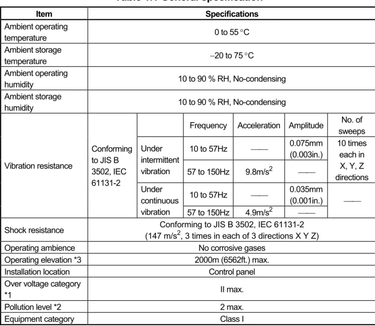
1. SPECIFICATIONS 1.1 SPECIFICATIONS
Table 1.1 General specification
Item Specifications
Ambient operating
temperature 0 to 55 °C
Ambient storage
temperature −20 to 75 °C
Ambient operating
humidity 10 to 90 % RH, No-condensing
Ambient storage
humidity 10 to 90 % RH, No-condensing
Frequency Acceleration Amplitude No. of sweeps 10 to 57Hz ⎯⎯ 0.075mm
(0.003in.) Under
intermittent
vibration 57 to 150Hz 9.8m/s2 ⎯⎯
10 times each in X, Y, Z directions 10 to 57Hz ⎯⎯ 0.035mm
(0.001in.) Vibration resistance
Conforming to JIS B 3502, IEC 61131-2
Under continuous
vibration 57 to 150Hz 4.9m/s2 ⎯⎯
⎯⎯
Shock resistance Conforming to JIS B 3502, IEC 61131-2 (147 m/s2, 3 times in each of 3 directions X Y Z)
Operating ambience No corrosive gases
Operating elevation *3 2000m (6562ft.) max.
Installation location Control panel
Over voltage category
*1 II max.
Pollution level *2 2 max.
Equipment category Class I
*1: This indicates the section of the power supply to which the equipment is assumed to be connected between the public electrical power distribution network and the machinery within premises. Category II applies to equipment for which electrical power is supplied from fixed facilities. The surge voltage withstand level for up to the rated voltage of 300 V is 2500 V.
*2: This index indicates the degree to which conductive material is generated in terms of the environment in which the equipment is used. Pollution level 2 is when only non-conductive pollution occurs. A temporary conductivity caused by condensing must be expected occasionally.
*3: Do not use or store the PC in the environment when the pressure is higher than
the atmospheric pressure at sea level. Otherwise, malfunction may result. To
use the PC in high-pressure environment, contact your nearest Mitsubishi
representative.
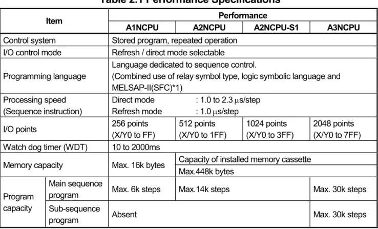
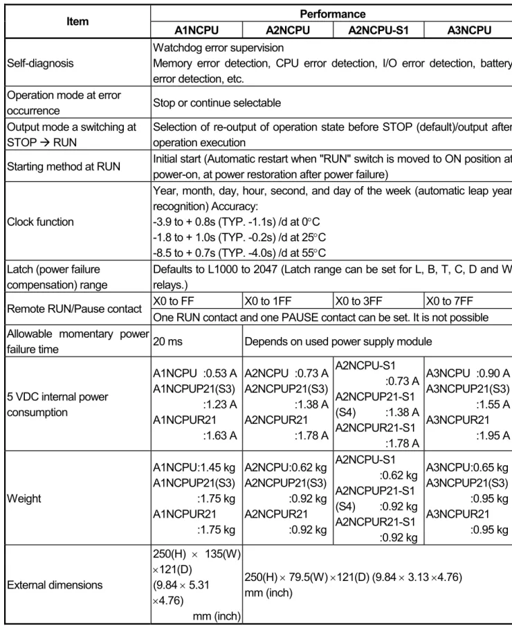
2. Performance Specifications
2.1 CPU Module Performance Specifications
2.1.1 AnNCPU Module Performance Specifications
Table 2.1 shows the memory capacities of the CPU modules and the performance of their devices.
Table 2.1 Performance Specifications
Performance Item
A1NCPU A2NCPU A2NCPU-S1 A3NCPU Control system Stored program, repeated operation
I/O control mode Refresh / direct mode selectable Programming language
Language dedicated to sequence control.
(Combined use of relay symbol type, logic symbolic language and MELSAP-II(SFC)*1)
Processing speed (Sequence instruction)
Direct mode : 1.0 to 2.3 μs/step Refresh mode : 1.0 μs/step
I/O points 256 points
(X/Y0 to FF)
512 points (X/Y0 to 1FF)
1024 points (X/Y0 to 3FF)
2048 points (X/Y0 to 7FF) Watch dog timer (WDT) 10 to 2000ms
Capacity of installed memory cassette Memory capacity Max. 16k bytes
Max.448k bytes Main sequence
program Max. 6k steps Max.14k steps Max. 30k steps Program
capacity Sub-sequence
program Absent Max. 30k steps
*1 The SFC language cannot be used with an A1NCPU.
Table 2.1 Performance Specifications (Continued)
Performance Item
A1NCPU A2NCPU A2NCPU-S1 A3NCPU Self-diagnosis
Watchdog error supervision
Memory error detection, CPU error detection, I/O error detection, battery error detection, etc.
Operation mode at error
occurrence Stop or continue selectable Output mode a switching at
STOP Æ RUN
Selection of re-output of operation state before STOP (default)/output after operation execution
Starting method at RUN Initial start (Automatic restart when "RUN" switch is moved to ON position at power-on, at power restoration after power failure)
Clock function
Year, month, day, hour, second, and day of the week (automatic leap year recognition) Accuracy:
-3.9 to + 0.8s (TYP. -1.1s) /d at 0°C -1.8 to + 1.0s (TYP. -0.2s) /d at 25°C -8.5 to + 0.7s (TYP. -4.0s) /d at 55°C Latch (power failure
compensation) range
Defaults to L1000 to 2047 (Latch range can be set for L, B, T, C, D and W relays.)
X0 to FF X0 to 1FF X0 to 3FF X0 to 7FF Remote RUN/Pause contact
One RUN contact and one PAUSE contact can be set. It is not possible Allowable momentary power
failure time 20 ms Depends on used power supply module
5 VDC internal power consumption
A1NCPU :0.53 A A1NCPUP21(S3)
:1.23 A
A1NCPUR21
:1.63 A
A2NCPU :0.73 A A2NCPUP21(S3)
:1.38 A
A2NCPUR21
:1.78 A
A2NCPU-S1
:0.73 A
A2NCPUP21-S1 (S4) :1.38 A A2NCPUR21-S1
:1.78 A
A3NCPU :0.90 A A3NCPUP21(S3)
:1.55 A
A3NCPUR21
:1.95 A
Weight
A1NCPU :1.45 kg A1NCPUP21(S3)
:1.75 kg
A1NCPUR21
:1.75 kg
A2NCPU :0.62 kg A2NCPUP21(S3)
:0.92 kg
A2NCPUR21
:0.92 kg
A2NCPU-S1
:0.62 kg
A2NCPUP21-S1 (S4) :0.92 kg A2NCPUR21-S1
:0.92 kg
A3NCPU :0.65 kg A3NCPUP21(S3)
:0.95 kg
A3NCPUR21
:0.95 kg
External dimensions
250(H) × 135(W)
×121(D) (9.84 × 5.31
×4.76)
mm (inch)
250(H) × 79.5(W) ×121(D) (9.84 × 3.13 ×4.76) mm (inch)
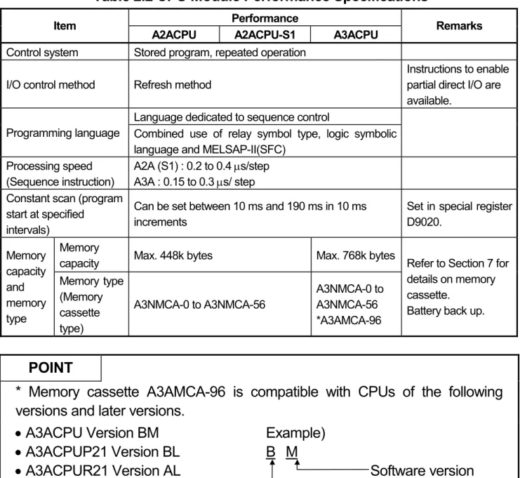
2.1.2 AnACPU Module performance specifications
Table 2.2 shows the performance specifications of the AnACPU module. Since the valid range for setting each device differs, use caution when a previous system FD, peripheral devices or an AnACPU compatible system FD are used.
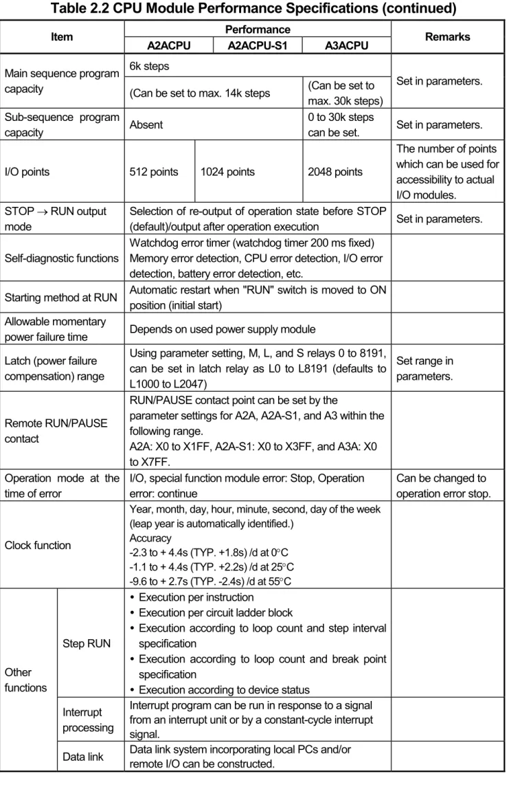
Table 2.2 CPU Module Performance Specifications
Performance Item
A2ACPU A2ACPU-S1 A3ACPU Remarks
Control system Stored program, repeated operation I/O control method Refresh method
Instructions to enable partial direct I/O are available.
Language dedicated to sequence control
Programming language Combined use of relay symbol type, logic symbolic language and MELSAP-II(SFC)
Processing speed (Sequence instruction)
A2A (S1) : 0.2 to 0.4 μs/step A3A : 0.15 to 0.3 μs/ step Constant scan (program
start at specified intervals)
Can be set between 10 ms and 190 ms in 10 ms increments
Set in special register D9020.
Memory
capacity Max. 448k bytes Max. 768k bytes Memory
capacity and memory type
Memory type (Memory cassette type)
A3NMCA-0 to A3NMCA-56
A3NMCA-0 to A3NMCA-56
*A3AMCA-96
Refer to Section 7 for details on memory cassette.
Battery back up.
POINT
* Memory cassette A3AMCA-96 is compatible with CPUs of the following versions and later versions.
• A3ACPU Version BM
• A3ACPUP21 Version BL
• A3ACPUR21 Version AL
Example) B M
Software version
Hardware version
Table 2.2 CPU Module Performance Specifications (continued)
Performance Item
A2ACPU A2ACPU-S1 A3ACPU Remarks
6k steps Main sequence program
capacity (Can be set to max. 14k steps (Can be set to max. 30k steps)
Set in parameters.
Sub-sequence program
capacity Absent 0 to 30k steps
can be set. Set in parameters.
I/O points 512 points 1024 points 2048 points
The number of points which can be used for accessibility to actual I/O modules.
STOP → RUN output mode
Selection of re-output of operation state before STOP
(default)/output after operation execution Set in parameters.
Self-diagnostic functions
Watchdog error timer (watchdog timer 200 ms fixed) Memory error detection, CPU error detection, I/O error detection, battery error detection, etc.
Starting method at RUN Automatic restart when "RUN" switch is moved to ON position (initial start)
Allowable momentary
power failure time Depends on used power supply module Latch (power failure
compensation) range
Using parameter setting, M, L, and S relays 0 to 8191, can be set in latch relay as L0 to L8191 (defaults to L1000 to L2047)
Set range in parameters.
Remote RUN/PAUSE contact
RUN/PAUSE contact point can be set by the
parameter settings for A2A, A2A-S1, and A3 within the following range.
A2A: X0 to X1FF, A2A-S1: X0 to X3FF, and A3A: X0 to X7FF.
Operation mode at the time of error
I/O, special function module error: Stop, Operation error: continue
Can be changed to operation error stop.
Clock function
Year, month, day, hour, minute, second, day of the week (leap year is automatically identified.)
Accuracy
-2.3 to + 4.4s (TYP. +1.8s) /d at 0°C -1.1 to + 4.4s (TYP. +2.2s) /d at 25°C -9.6 to + 2.7s (TYP. -2.4s) /d at 55°C
Step RUN
y Execution per instruction
y Execution per circuit ladder block
y Execution according to loop count and step interval specification
y Execution according to loop count and break point specification
y Execution according to device status Interrupt
processing
Interrupt program can be run in response to a signal from an interrupt unit or by a constant-cycle interrupt signal.
Other functions
Data link Data link system incorporating local PCs and/or remote I/O can be constructed.
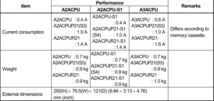
Table 2.2 CPU Module Performance Specifications (continued)
Performance Item
A2ACPU A2ACPU-S1 A3ACPU Remarks
Current consumption
A2ACPU : 0.4 A A2ACPUP21(S3)
: 1.0 A A2ACPUR21
: 1.4 A
A2ACPU-S1 : 0.4 A A2ACPUP21-S1 (S4) : 1.0 A A2ACPUR21-S1
: 1.4 A
A3ACPU : 0.6 A A3ACPUP21(S3)
: 1.0 A A3ACPUR21
: 1.6 A
Differs according to memory cassette.
Weight
A2ACPU : 0.7 kg A2ACPUP21(S3)
: 0.9 kg A2ACPUR21
: 0.9 kg
A2ACPU-S1 : 0.7 kg A2ACPUP21-S1 (S4) : 0.9 kg A2ACPUR21-S1
: 0.9 kg
A3ACPU : 0.7 kg A3ACPUP21(S3)
: 0.9 kg A3ACPUR21
: 1.0 kg External dimensions 250(H) × 79.5(W) × 121(D) (9.84 × 3.13 × 4.76)
mm (inch)
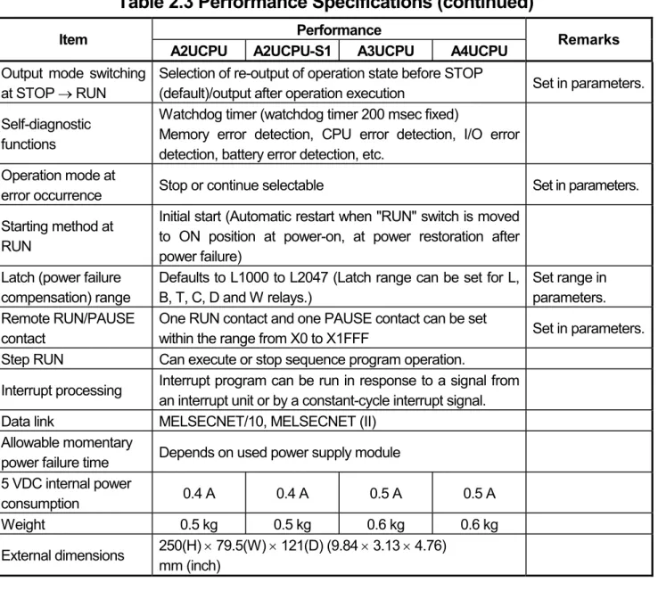
2.1.3 AnUCPU Module Performance Specifications
This section explains the performance specifications and devices of the AnUCPU.
Table 2.3 Performance Specifications
Performance Item
A2UCPU A2UCPU-S1 A3UCPU A4UCPU Remarks Control system Stored program, repeated operation
I/O control method Refresh method
Instructions to enable partial direct I/O are available.
Language dedicated to sequence control
Programming language Combined use of relay symbol type, logic symbolic language and MELSAP-II (SFC)
Processing speed
(Sequence instruction) 0.2 μs/step 0.15 μs/step
Constant scan (program start at specified intervals)
Can be set between 10 ms and 190 ms in 10 ms increments
Set in special register D9020.
Memory capacity
Capacity of installed memory cassette (Max. 448 kbytes)
Capacity of installed memory cassette (Max. 1024 kbytes) Main sequence
program Max. 14k steps Max. 30k steps Program
capacity Sub-sequence
program Absent Max. 30k
steps
Max. 30k steps × 3
Set in parameters.
I/O device points 8192 points (X/Y0 to 1FFF)
The number of points usable in the program
I/O points
512 points (X/Y0 to 1FF)
1024 points (X/Y0 to 3FF)
2048 points (X/Y0 to 7FF)
4096 points (X/Y0 to FFF)
The number of points which can be used for accessibility to actual I/O modules
Table 2.3 Performance Specifications (continued)
Performance Item
A2UCPU A2UCPU-S1 A3UCPU A4UCPU Remarks Output mode switching
at STOP → RUN
Selection of re-output of operation state before STOP
(default)/output after operation execution Set in parameters.
Self-diagnostic functions
Watchdog timer (watchdog timer 200 msec fixed)
Memory error detection, CPU error detection, I/O error detection, battery error detection, etc.
Operation mode at
error occurrence Stop or continue selectable Set in parameters.
Starting method at RUN
Initial start (Automatic restart when "RUN" switch is moved to ON position at power-on, at power restoration after power failure)
Latch (power failure compensation) range
Defaults to L1000 to L2047 (Latch range can be set for L, B, T, C, D and W relays.)
Set range in parameters.
Remote RUN/PAUSE contact
One RUN contact and one PAUSE contact can be set
within the range from X0 to X1FFF Set in parameters.
Step RUN Can execute or stop sequence program operation.
Interrupt processing Interrupt program can be run in response to a signal from an interrupt unit or by a constant-cycle interrupt signal.
Data link MELSECNET/10, MELSECNET (II) Allowable momentary
power failure time Depends on used power supply module 5 VDC internal power
consumption 0.4 A 0.4 A 0.5 A 0.5 A
Weight 0.5 kg 0.5 kg 0.6 kg 0.6 kg
External dimensions 250(H) × 79.5(W) × 121(D) (9.84 × 3.13 × 4.76) mm (inch)
CAUTION
When the existing system software package and peripheral devices are used, the
applicable device range is limited.
3. EMC DIRECTIVES AND LOW VOLTAGE DIRECTIVES
The products sold in the European countries have been required by law to comply with the EMC Directives and Low Voltage Directives of the EU Directives since 1996 and 1997, respectively.
The manufacturers must confirm by self-declaration that their products meet the requirements of these directives, and put the CE mark on the products.
3.1 Requirements for Compliance with EMC Directives
The EMC Directives specifies emission and immunity criteria and requires the products to meet both of them, i.e., not to emit excessive electromagnetic interference (emission): to be immune to electromagnetic interference outside (immunity).
Guidelines for complying the machinery including MELSEC-A series PLC with the EMC Directives are provided in Section 3.1.1 to 3.1.6 below.
The guidelines are created based on the requirements of the regulations and relevant standards, however, they do not guarantee that the machinery constructed according to them will not comply with the Directives.
Therefore, the manufacturer of the machinery must finally determine how to make it
comply with the EMC Directives: if it is actually compliant with the EMC Directives.
3.1.1 EMC standards
When the PLC is installed following the directions given in this manual its EMC performance is compliant to the following standards and levels as required by the EMC directive.
Specifications Test Item Test Description Standard Values EN55011 *2
Radiated noise
Measure the emission released by the product.
30M-230 M Hz QP: 30dBμ V/m (30m measurement) *1
230M-1000MHz QP: 37dBμ V/m (30m measurement) *1 EN61000-6-4
(2001)
EN55011 *2 Conduction noise
Measure the emission released by the product to the power line.
150k-500kHz QP:
79dB, Mean: 66dB*1 500k-30MHz QP:
73dB, Mean: 60dB *1 EN61000-4-2 *2
Static electricity immunity
Immunity test by applying static electricity to the module enclosure.
4kV contact discharge 8kV air discharge EN61000-4-4 *2
First transient burst noise
Immunity test by applying burst noise to the power line and signal line.
2kV Power line 1kv Signal line EN61000-4-12 *2
Damped oscillatory wave
Immunity test in which a damped oscillatory wave is superimposed on the power line.
1kv EN61131-2/A12
(2000)
EN61000-4-3 *2 Radiated
electromagnetic field
Immunity test by applying a radiated electric field to the product.
10V/m, 26-1000MHz EN61000-6-2
(2001)
EN61000-4-6 *2 Conduction noise
Immunity test by inducting an electromagnetic field in the power line signal line.
10 V/ms, 0.15-80MHZ, 80% AM modulation@1kHz
*1: QP: Quasi-peak value, Mean: Average value
*2: The PLC is an open type device (device installed to another device) and must be installed in a conductive control panel.
The tests for the corresponding items were performed while the PLC was
installed inside the control panel.
3.1.2 Installation instructions for EMC Directive
The PLC is open equipment and must be installed within a control cabinet for use.* This not only ensures safety but also ensues effective shielding of PLC-generated electromagnetic noise.
* : Also, each network remote station needs to be installed inside the control panel.
However, the waterproof type remote station can be installed outside the control panel.
(1) Control cabinet
(a) Use a conductive control cabinet.
(b) When attaching the control cabinet's top plate or base plate, mask painting and weld so that good surface contact can be made between the cabinet and plate.
(c) To ensure good electrical contact with the control cabinet, mask the paint on the installation bolts of the inner plate in the control cabinet so that contact between surfaces can be ensured over the widest possible area.
(d) Earth the control cabinet with a thick wire so that a low impedance connection to ground can be ensured even at high frequencies.
(e) Holes made in the control cabinet must be 10 cm (3.94 in.) diameter or less. If the holes are 10 cm (3.94 in.) or larger, radio frequency noise may be emitted.
In addition, because radio waves leak through a clearance between the control panel door and the main unit, reduce the clearance as much as practicable.
The leakage of radio waves can be suppressed by the direct application of an EMI gasket on the paint surface.
Our tests have been carried out on a panel having the damping characteristics of 37 dB max. and 30 dB mean (measured by 3 m method with 30 to 300 MHz).
(2) Connection of power and earth wires
Earthing and power supply wires for the PLC system must be connected as described below.
(a) Provide an earthing point near the power supply module. Earth the power supply's LG and FG terminals (LG: Line Ground, FG: Frame Ground) with the thickest and shortest wire possible. (The wire length must be 30 cm (11.81 in.) or shorter.) The LG and FG terminals function is to pass the noise generated in the PLC system to the ground, so an impedance that is as low as possible must be ensured. In addition, make sure to wire the ground cable short as the wires are used to relieve the noise, the wire itself carries large noise content and thus short wiring means that the wire is prevented from acting as an antenna.
(b) The earth wire led from the earthing point must be twisted with the power
supply wires. By twisting with the earthing wire, noise flowing from the
power supply wires can be relieved to the earthing. However, if a filter is
installed on the power supply wires, the wires and the earthing wire may
not need to be twisted.
3.1.3 Cables
The cables pulled out of the control panel contain a high frequency noise component. On the outside of the control panel, therefore, they serve as antennas to emit noise.
Ensure to use shielded cables for the cables, which are connected to the I/O modules, special modules and those pulled out to outside of the control panel.
Mounting ferrite core is not required except some types of CPU however, noise emanated via the cable can be restrained using it.
The use of a shielded cable also increases noise resistance. The signal lines (including common line) connected to the PLC input/output modules and intelligent modules use shielded cables to assure noise resistance, as a condition, standardized on EN61131-2/A12(2000).
If a shielded cable is not used or not earthed correctly, the noise resistance will be less than the rated value
(1) Earthing of shielded of cables
(a) Earth the shield of the shielded cable as near the unit as possible taking care so that the earthed cables are not induced electromagnetically by the cable to be earthed.
(b) Take appropriate measures so that the shield section of the shielded cable from which the outer cover was partly removed for exposure is earthed to the control panel on an increased contact surface. A clamp may also be used as shown in the figure below. In this case, however, apply a cover to the painted inner wall surface of the control panel which comes in contact with the clamp.
Shield section
Screw
Shielded cable Paint mask
Clamp fitting
Note) The method of earthing by soldering a wire onto the shield section of the shielded cable as shown below is not recommended. The high frequency impedance will increase and the shield will be ineffective.
Shielded cable Wire
Crimp terminal
(2) MELSECNET (II) and MELSECNET/10 units
(a) Use a double-shielded coaxial cable for the MELSECNET unit which uses coaxial cables. Noise in the range of 30 MHz or higher in radiation noise can be suppressed by the use of double-shielded coaxial cables (Mitsubishi Cable: 5C-2V-CCY). Earth the outer shield to the ground.
The precautions on shielding to be followed are the same as those stated in item (1) above.
Earth this section Shield
(b) Ensure to attach a ferrite core to the double-shielded coaxial cable connected to the MELSECNET unit. In addition, position the ferrite core on each cable near the outlet of the control panel. TDK-make ZCAT3035 ferrite core is recommended.
(3) Ethernet module
Precautions to be followed when AUI cables and coaxial cables are used are described below.
(a) Ensure to earth also the AUI cables connected to the 10BASE5 connectors of the A1SJ71QE71-B5. Because the AUI cable is of the shielded type, as shown in the figure below, partly remove the outer cover of it, and earth the exposed shield section to the ground on the widest contact surface.
Shield AUI cable
(b) Use shielded twisted pair cables as the twisted pair cables*1 connected to the 10BASE-T connectors. For the shielded twisted pair cables, strip part of the outer cover and earth the exposed shield section to the ground on the widest contact surface as shown below.
Shield
Shielded twisted pair cables
Refer to (1) for the earthing of the shield.
*1: Make sure to install a ferrite core for the cable.
As a ferrite core, ZCAT2035 manufactured by TDK is recommended.
(c) Always use double-shielded coaxial cables as the coaxial cables*2 connected to the 10BASE2 connectors. Earth the double-shielded coaxial cable by connecting its outer shield to the ground.
Earth here Shield
Refer to (1) for the earthing of the shield.
*2: Make sure to install a ferrite core for the cable.
As a ferrite core, ZCAT2035 manufactured by TDK is recommended.
Ethernet is the registered trademark of XEROX, Co.,LTD (4) I/O and other communication cables
For the I/O signal lines (including common line) and other communication cables (RS-232, RS-422, etc), if extracted to the outside of the control panel, also ensure to earth the shield section of these lines and cables in the same manner as in item (1) above.
(5) Positioning Modules
Precautions to be followed when the machinery conforming to the EMC Directive is configured using the AD75P -S3 are described below.
(a) When wiring with a 2 m (6.56 ft.) or less cable
• Ground the shield section of the external wiring cable with the cable clamp.
(Ground the shield at the closest location to the AD75 external wiring connector.)
• Wire the external wiring cable to the drive unit and external device with the shortest practicable length of cable.
• Install the drive unit in the same panel.
Power supply module CPU module AD75 module
Drive unit External wiring connector
External wiring cable (within 2m (6.56 ft.)) Cable clamp
(b) When wiring with cable that exceeds 2 m (6.56 ft.), but is 10 m (32.81 ft.) or less
• Ground the shield section of the external wiring cable with the cable clamp.
(Ground the shield at the closest location to the AD75 external wiring connector.)
• Install a ferrite core.
• Wire the external wiring cable to the drive unit and external device with the shortest practicable length of cable.
Power supply module CPU module AD75 module
Drive unit External wiring connector
Ferrite core
External wiring cable (2m to 10m (6.56 ft. to 32.81 ft.)) Cable clamp
(c) Ferrite core and cable clamp types and required quantities
• Cable clamp
Type : AD75CK (Mitsubishi Electric)
• Ferrite core
Type : ZCAT3035-1330 (TDK ferrite core)
• Required quantity
Required Qty Cable length Prepared part
1 axis 2 axes 3 axes
Within 2 m (6.56 ft.) AD75CK 1 1 1
AD75CK 1 1 1
2 m (6.56 ft.) to 10m (32.81 ft.)
ZCAT3035-1330 1 2 3
AD75
Inside control panel
AD75CK 20 to 30cm(7.87 to 11.81inch)
(6) CC-Link Module
(a) Be sure to ground the cable shield that is connected to the CC-Link
module close to the exit of control panel or to any of the CC-Link stations within 30 cm (11.81 in.) from the module or stations.
The CC-Link dedicated cable is a shielded cable. As shown in the
illustration below, remove a portion of the outer covering and ground as large a surface area of the exposed shield part as possible.
CC-Link dedicated cable Shield
(b) Always use the specified CC-Link dedicated cable.
(c) The CC-Link module, the CC-Link stations and the FG line inside the control panel should be connected at the FG terminal as shown in the diagram below.
[Simplified diagram]
Terminal resistor
Master module Remote module Local module
Terminal resistor CC-Link
dedicated cable CC-Link
dedicated cable DA
DB DG SLD
FG
DA DB DG SLD
FG
DA DB DG SLD
FG
(Blue) (White) (Yellow)
(d) Power line connecting to the external power supply terminal (compliant with I/O power port of CE standard) should be 30m (98.43 ft.) or less.
Power line connecting to module power supply terminal (compliant with main power port of CE standard) should be 10m (32.81 ft.) or less.
(e) A power line connecting to the analog input of the following modules should be 30cm or less.
• AJ65BT-64RD3
• AJ65BT-64RD4
• AJ65BT-68TD
3.1.4 Power supply module
The precautions required for each power supply module are described below.
Always observe the items noted as precautions.
Model name Precautions
A61P, A61PN, A62P N/A
A63P Use a CE-compliant 24VDC power supply in the control panel.
A61PEU, A62PEU, A1NCPU (Power supply part)
Make sure to short and ground the LG and FG
terminals.
3.1.5 Ferrite core
Use of ferrite cores is effective in reducing the conduction noise in the band of about 10 MHz and radiated noise in 30 to 100 MHz band.
It is recommended to attach ferrite cores when the shield of the shielded cable coming out of control panel does not work effectively, or when emission of the conduction noise from the power line has to be suppressed.*1 The ferrite cores used in our tests are TDK's ZCAT3035.
It should be noted that the ferrite cores should be fitted to the cables in the position immediately before they are pulled out of the enclosure. If the fitting position is improper, the ferrite will not produce any effect.
1:To response with CE(EN61131-2/A12), make sure to mount 2 or more ferrite cores onto the power supply line. The mounting position should be as near the power supply module as possible.
Ferrite core
Type: ZCAT2235-1030A (TDK ferrite core)
3.1.6 Noise filter (power supply line filter)
A noise filter is a component which has an effect on conducted noise. With the exception of some models, it is not required to fit the noise filter to the power supply line, but fitting it can further suppress noise. (The noise filter has the effect of reducing conducted noise of 10 M Hz or less.) Use any of the following noise filters (double type filters) or equivalent.
Model name FN343-3/01 FN660-6/06 ZHC2203-11
Manufacturer SCHAFFNER SCHAFFNER TDK
Rated current 3 A 6 A 3 A
Rated voltage 250 V
The precautions required when installing a noise filter are described below.
(1) Do not bundle the wires on the input side and output side of the noise filter.
When bundled, the output side noise will be induced into the input side wires from which the noise was filtered.
Filter
Induction
Output side (device side) Input side
(power supply side)
Filter
Output side (device side) Input side
(power supply side)
(a) The noise will be
included when the input and output wires are bundled.
(b) Separate and lay the input and output wires.
(2) Earth the noise filter earthing terminal to the control cabinet with the
shortest wire possible (approx. 10 cm (3.94 in.)).
3.2 Requirements for Compliance with Low Voltage Directives
The Low Voltage Directives apply to the electrical equipment operating from 50 to 1000VAC or 75 to 1500VDC; the manufacturer must ensure the adequate safety of the equipment.
Guidelines for installation and wiring of MELSEC-A series PLC are provided in Section 3.2.1 to 3.2.7 for the purpose of compliance with the EMC Directives.
The guidelines are created based on the requirements of the regulations and relevant standards, however, they do not guarantee that the machinery constructed according to them will comply with the Directives.
Therefore, the manufacturer of the machinery must finally determine how to make it comply with the EMC Directives: if it is actually compliant with the EMC Directives.
3.2.1 Standard applied for MELSEC-A series PLC
The standard applied for MELSEC-A series PLC series is EN61010-1 safety of devices used in measurement rooms, control rooms, or laboratories.
For the modules which operate with the rated voltage of 50 VAC/75 VDC or above, we have developed new models that conform to the above standard.
For the modules which operate with the rated voltage under 50 VAC/75 VDC, the conventional models can be used, because they are out of the low voltage directive application range.
3.2.2 Precautions when using the MELSEC-A series PLC Module selection
(1) Power module
For a power module with rated input voltage of 100/200 VAC, select a model in which the internal part between the first order and second order is intensively insulated, because it generates hazardous voltage (voltage of 42.4 V or more at the peak) area.
For a power module with 24 VDC rated input, a conventional model can be used.
(2) I/O module
For I/O module with rated input voltage of 100/200 VAC, select a model in which the internal area between the first order and second order is
intensively insulated, because it has hazardous voltage area.
For I/O module with 24 VDC rated input, a conventional model can be used.
(3) CPU module, memory cassette, base unit
Conventional models can be used for these modules, because they only have a 5 VDC circuit inside.
(4) Special function module
Conventional models can be used for the special modules including analog module, network module, and positioning module, because the rated
voltage is 24 VDC or smaller.
(5) Display device
Use the CE-marked product.
3.2.3 Power supply
The insulation specification of the power module was designed assuming installation category II. Be sure to use the installation category II power supply to the PLC.
The installation category indicates the durability level against surge voltage
generated by a thunderbolt. Category I has the lowest durability; category IV has the highest durability.
Category III Category II Category I Category IV
Figure 1: Installation Category
Category II indicates a power supply whose voltage has been reduced by two or more levels of isolating transformers from the public power distribution.
3.2.4 Control panel
Because the PLC is an open device (a device designed to be stored within another module), be sure to use it after storing in the control panel.
(1) Electrical shock prevention
In order to prevent persons who are not familiar with the electric facility such as the operators from electric shocks, the control panel must have the
following functions:
(a) The control panel must be equipped with a lock so that only the
personnel who has studied about the electric facility and have enough knowledge can open it.
(b) The control panel must have a structure which automatically stops the power supply when the box is opened.
(c) For electric shock protection, use IP20 or greater control panel.
(2) Dustproof and waterproof features
The control panel also has the dustproof and waterproof functions.
Insufficient dustproof and waterproof features lower the insulation withstand voltage, resulting in insulation destruction. The insulation in our PLC is designed to cope with the pollution level 2, so use in an environment with pollution level 2 or below.
Pollution level 1: An environment where the air is dry and conductive dust does not exist.
Pollution level 2: An environment where conductive dust
does not usually exist, but occasional temporary conductivity occurs due to the accumulated dust. Generally, this is the level for inside the control panel equivalent to IP54 in a control room or on the floor of a typical factory.
Pollution level 3: An environment where conductive dust exits and conductivity may be generated due to the accumulated dust.
An environment for a typical factory floor.
Pollution level 4: Continuous conductivity may occur due to rain, snow, etc. An outdoor environment.
As shown above, the PLC can realize the pollution level 2 when stored in a
control panel equivalent to IP54.
3.2.5 Module installation
(1) Installing modules contiguously
In Q2AS series PLCs, the left side of each I/O module is left open. When installing an I/O module to the base, do not make any open slots between any two modules. If there is an open slot on the left side of a module with 100/200 VAC rating, the printed board which contains the hazardous
voltage circuit becomes bare. When it is unavoidable to make an open slot, be sure to install the blank module (AG60).
3.2.6 Grounding
There are two kinds of grounding terminals as shown below. Either grounding terminal must be used grounded.
Be sure to ground the protective grounding for the safety reasons.
Protective grounding : Maintains the safety of the PLC and improves the noise resistance.
Functional grounding : Improves the noise resistance.
3.2.7 External wiring
(1) Module power supply and external power supply
For the remote module which requires 24VDC as module power supply, the 5/12/24/48VDC I/O module, and the special function module which requires the external power supply, use the 5/12/24/48VDC circuit which is doubly insulated from the hazardous voltage circuit or use the power supply whose insulation is reinforced.
(2) External devices
When a device with a hazardous voltage circuit is externally connected to the PLC, use a model whose circuit section of the interface to the PLC is intensively insulated from the hazardous voltage circuit.
(3) Intensive insulation
Intensive insulation refers to the insulation with the dielectric withstand voltage shown in Table 1.
Table 1: Intensive Insulation Withstand Voltage (Installation Category II, source: IEC664)
Rated voltage of hazardous voltage area Surge withstand voltage (1.2/50 µs)
150 VAC or below 2500 V
300 VAC or below 4000 V
4. LOADING AND INSTALLATION 4.1 Installing Modules
4.1.1 Notes on handling the module
This section explains some notes on handling the CPU module, I/O module, special function module, power supply module, and base unit.
(1) Do not drop or allow any impact to the modules case, memory card, terminal block cover, or pin connector.
(2) Do not remove modules' printed circuit boards from the plastic casing.
(3) Use caution to prevent foreign matter, such as wire chips, falling into the module during wiring. If foreign matter enters the module, remove it.
(4) Tighten the module mounting (unnecessary in normal operating condition) and terminal block screws as indicated below.
Screw Tightening Torque Nxcm
Module mounting screws (M4 screw) (optional) 78 to 118
Terminal block screws 98 to 137
(5) To install a module, push it firmly into the base unit so that the latch engages properly. To remove a module, press the latch to disengage it from the base unit, then pull the module out (for details, refer to the relevant PC CPU User's Manual.
4.1.2 Installation environment
The CPU system should not be installed under the following environmental conditions:
(1) A location in which the ambient temperature falls outside the range of 0 to 55 degrees Celsius.
(2) A location in which the ambient humidity falls outside the range of 10 to 90%RH.
(3) A location in which condensation may occur due to drastic changes in
temperature.
(4) A location in which corrosive gas or flammable gas exists.
(5) A location in which the system is easily exposed to conductive powder, such as dust and iron filings, oil mist, salt, or organic solvent.
(6) A location exposed to direct sunlight.
(7) A location in which strong electrical or magnetic fields are generated.
(8) A location in which the module is exposed to direct vibration or impact.
4.1.3 Notes on installing the base unit
Take ease of operation, ease of maintenance, and environmental durability into consideration when you are installing the PLC on the panel.
(1) Mounting dimension
Mounting dimensions of each base unit are as follows.
CPU UNIT I/O0 I/O1 I/O2 I/O3 I/O4 I/O5 I/O6 I/O7
POWER
Hs
Ws W
H
A38B
A32B A32B-S1 A35B A38B A62B A65B A68B A52B A55B A58B
W 247
(9.72)
268 (10.55)
382 (15.03)
480 (18.9)
238 (9.37)
352 (13.86)
466 (18.35)
183 (7.2)
297 (11.69)
411 (16.18) Ws 227
(8.93)
248 (9.76)
362 (14.25)
460 (18.11)
218 (8.58)
332 (13.07)
446 (17.6)
163 (6.42)
277 (10.9)
391 (15.4)
H 250 (9.84)
Hs 200 (7.87)
Dimensions: mm (inch)
(2) Module installation position
To ensure proper ventilation and make module replacement easy, provide a clearance of 80mm (3.15in.) or more between the top of the unit and any surrounding structure or equipment.
(1.10 in.)28mm 39mm (1.54 in.) For coaxial
data link For optical data link
Main base unit Extension base unit80mm (3.15 in.) or more
*3 Parallel installation
Represents the ceiling of panel, wiring conduit, or component.
(3) A wiring conduit should be provided if required.
If its clearance above or below the programmable controller is less than indicated in the figure above, observe the following points:
(a) If the wiring conduit is installed above the programmable controller, its height must be no greater than 50 mm (1.97in.) to ensure good ventilation.
In addition, there should be adequate space between the programmable controller and the wiring conduit to allow module latches to be pressed.
It will not be possible to replace modules if their latches cannot be
pressed.
(b) If the wiring conduit is installed below the programmable controller, it should be installed so as to allow connection of the optical fiber cable or coaxial cable, taking the minimum bending radius of the cable into consideration.
Conduit (50mm (1.97 in.) or less)
Main base unit
Extension base unit
80mm (3.15 in.) or more
*2
*1
*3 Serial installation
Represents the ceiling of panel, wiring conduit, or component.
80mm (3.15 in.) or more
*1 : These dimensions vary depending on the length of the extension cable as follows:
AC06B cable... 450mm (17.71in.) or less AC12B cable... 1050mm (41.34in.) or less AC30B cable... 2850mm (112.20in.) or less
*2 : When a link module is not used... 50mm (1.97in.) or more When using φ4.5mm optical fiber cable,
or coaxial cable... 100mm (3.94in.) or more When using φ8.5mm optical fiber cable ... 130mm (5.12in.) or more
*3 : When a link module is not used... 50mm (1.97in.) or more When using φ4.5mm optical fiber cable,
or coaxial cable ... 100mm (3.94in.) or more
When using φ8.5mm optical fiber cable ... 130mm (5.12in.) or more
(4) Module installation direction
(a) Use the PLC in the following position for better ventilation and heat dissipation:
(b) Do not use the PLC in the following positions:
Vertical position Horizontal position
(5) Install the base unit on a level surface.
If the surface is not level, force may be applied to the printed wiring board, causing a malfunction.
(6) Install the unit far from any source of vibration, such as a large magnetic contactor and a no-fuse breaker on the same panel, or install it on a separate panel.
(7) Keep the following distance between the PLC and other devices (such as a contactor and a relay) in order to avoid the influence of radiated noise and heat:
y a device installed in front of the PLC ...100mm (3.94 inch) or more y a device installed on the right or left of the PLC ... 50mm (1.97 inch) or more
100mm (3.94 inch)
or more 50mm (1.97 inch)
or more Contactor and
relay, etc.
50mm (1.97 inch) or more
![[2016-Spring] WNFA Lab4](data:image/gif;base64,R0lGODlhAQABAIAAAP///wAAACH5BAEAAAAALAAAAAABAAEAAAICRAEAOw==)