國立臺灣大學工學院土木工程學系 碩士論文
Department of Civil Engineering College of Engineering National Taiwan University
Master Thesis
越南 RC 構件耐震設計與鋼筋配置之案例研究
—以 EN 1998-1:2004 與 ACI 318-08 規範為標準 Seismic Design and Detailing
of Reinforced Concrete Members in Vietnam Based on EN 1998-1:2004 and ACI 318-08 Codes
阮良平
Nguyen Luong Binh
指導教授:黃世建 教授 Advisor: Hwang, Shyh-Jiann
中華民國 99 年 6 月 June 2010
國 立 臺灣 大 學 土 木 工程 學 系
越 南
RC
構 件 耐震 設 計 與鋼 筋 配 置之 案 例研 究
—
以
EN1998-1:2004
與
ACI318-08
規 範為 標 準
99 6 阮 良 平 撰 碩 士 論 文
國立臺灣大學工學院土木工程學系 碩士論文
Department of Civil Engineering College of Engineering National Taiwan University
Master Thesis
越南 RC 構件耐震設計與鋼筋配置之案例研究
—以 EN1998-1:2004 與 ACI318-08 規範為標準
Seismic Design and Detailing
of Reinforced Concrete Members in Vietnam Based on EN 1998-1:2004 and ACI 318-08 Codes
阮良平
Nguyen Luong Binh
ABSTRACT
Codes of practice of Europe and United States of America are shared with many countries in the world. In fields of civil and structural engineering, EN Eurocodes and ACI codes (American Concrete Institute) are commonly used and they have been constantly updated according to technology advancement of human beings. Many countries have adopted EN Eurocodes or ACI codes as their national codes.
The author would like to focus this study on the common construction problems in high rise buildings encountered in Vietnam, which deals with wide beam-column joints, beam-core wall joints, coupling beams and deep beams. These construction problems are first briefly described. The related seismic design and detailing are then compared and evaluated by using the EN 1998-1:2004 and ACI 318-08 codes. This study is expected to clarify some common mistakes and to improve the construction practice in Vietnam.
Keywords: wide beam-column joint, beam-core wall joint, anchorage, coupling beams, deep beams, transfer beams, strut-and-tie model, earthquake-resistant structures, high rise buildings.
ACKNOWLEDGMENTS
I would like to express very special thanks to Master Joint Program between National Taiwan University (Taiwan) and University of Civil Engineering (Vietnam), especially Department of Civil Engineering, National Taiwan University for giving me on the Program.
I would like to express my endless thanks to Professor Kou-Chun Chang, Director of National Center for Research on Earthquake Engineering, former Chairman of Civil Engineering Department (National Taiwan University); Professor Liang-Jenq Leu, Chairman of Civil Engineering Department (National Taiwan University), former Coordinator of Joint Master Program; Professor Nguyen Manh Hung, former Rector of University of Civil Engineering (Vietnam), Associate Professor Le Van Thanh, Rector of University of Civil Engineering, and Associate Professor Do Huu Thanh, Coordinator of Joint Master Program in Vietnam.
I would like to express my gratitude and appreciation to my advisor, Professor Shyh-Jiann Hwang, National Taiwan University, whom without his advices I would not be able to complete my thesis. His helpful suggestions and kind support through the course and thesis allowed me to overcome numerous difficulties.
Special thanks are expressed to Indonesia and Vietnamese friends, like Erwin Lim, Hoang Vinh Long; to all my colleagues for their interest and willing assistance during my study in National Taiwan University.
I deeply thank my Director, Nguyen Van Cong, and Consultant and Inspection Joint Stock Company of Construction, Technology and Equipment-CONINCO, Department of Technical Management for its emotional and material support through my entries studies in Hanoi-Vietnam and Taipei-Taiwan.
Many special thanks to local companies, CECI Engineering Consultants, Inc., SINOTECH Engineering Consultants, Inc., and, CTCI Corporation, for its important financial support for Master Joint Program between National Taiwan University (Taiwan) and University of Civil Engineering (Vietnam).
I also wish to thank all Professors, staffs of Department of Civil Engineering and Office of International Affairs, National Taiwan University, National Center for Research on Earthquake Engineering (NCREE)-Taiwan, and University of Civil Engineering (Vietnam), who have made tremendous efforts during my study in Taiwan and Vietnam.
Finally, to my family, acknowledges their love, joy and trusts that you will each take home something good from the Taiwan experience.
TABLE OF CONTENTS
Page
ABSTRACT ... i
ACKNOWLEDGMENT ... ii
TABLE OF CONTENTS ... iv
LIST OF TABLES... vii
LIST OF FIGURES... ix
CHAPTER I. INTRODUCTION ...1
1.1 Brief on ACI 318-08 ...1
1.1.1 Brief on ACI ...1
1.1.2 Brief on ACI 318-08...1
1.2 Brief on EN and EN 1998-1:2004...3
1.2.1 Brief on EN...3
1.2.2 Brief on EN 1998...4
1.2.3 Brief on EN 1998-1:2004 ...6
1.3 Vietnam seismic risk ...7
1.3.1 Earthquake situation in Vietnam ...7
1.3.2 Conclusions ...8
1.4 Situations and difficulties in Vietnam’s civil engineering...8
1.4.1 Normative laws and regulations on technical standards...8
for the earthquake prevention and resistance for structures 1.4.1.1 State’s legal documents ...8
1.4.1.2 Design standards of reinforced concrete structures ...9
for earthquake resistance 1.4.2 Observance of legal documents, technique standards ...10
for the prevention and resistance of earthquake
1.4.3 Conclusions ...12
CHAPTER II. TYPICAL CONSTRUCTION PROBLEMS ...15
FACED IN VIETNAM 2.1 Problem 1: Wide beam-column joints and beam-core wall joints ...15
2.2 Problem 2: Coupling beams ...17
2.3 Problem 3: Deep beams in high rise buildings ...20
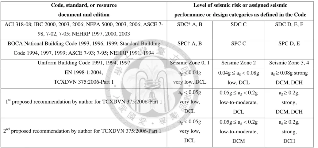
2.4 Seismic design category...21
CHAPTER III. WIDE BEAM-COLUMN JOINTS...25
AND BEAM-CORE WALL JOINTS 3.1 EN 1998-1:2004 ...25
3.2 ACI 318-08 ...29
3.3 Discussion ...32
3.4 Brief summary...46
CHAPTER IV. COUPLING BEAMS ...51
4.1 EN 1998-1:2004 ...51
4.2 ACI 318-08 ...52
4.3 Discussion ...53
4.4 Brief summary...59
CHAPTER V. DEEP BEAMS IN HIGH RISE BUILDINGS...61
5.1 EN 1998-1:2004 ...61
5.2 ACI 318-08 ...61
5.3 Discussion ...62
5.4 Brief summary...81
CHAPTER VI. CONCLUSIONS...85
NOTATIONS ...89
REFERENCES ...95
TABLES ...106
FIGURES ...144
APPENDIX A
-
EXAMPLES ON CHECK FOR DEEP BEAMS USING ...191 STRUT-AND-TIE MODELS (ACI 318-08)LIST OF TABLES
Table No. Title Page
1.1 Short history overview of the creation of the Eurocodes [3] ...106
1.2 Conversion between peak ground acceleration and earthquake intensity ...107
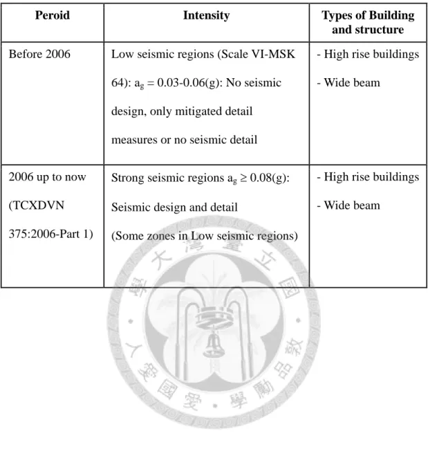
(Appendix K in TCXDVN 375:2006-Part 1[6]) 1.3 Timeline of the important legal documents in Vietnam ...108
2.1 Problems in codes of Vietnam, Europe, U.S. ...109
2.2-Correlation between seismic-related terminology in model codes...110
(Table R1.1.9.1, ACI 318-08) 2.3 Classification of earthquake level between ACI, EN, TCXDVN...110
2.4 Table of describing seismic zonation in P.R.China, S.R.Vietnam, U.S. ...111
2.5 Proposal for change of TCXDVN 375:2006-Part 1...111
2.6 Proposed solution for Vietnam’s seismic design ...112
2.7 Correlation between seismic design categories to seismic zones ...113
and recommendation 3.1 Major concepts on seismic design and detail in codes ...114
3.2 Main contents for design and detailing ...115
of wide beam-column connections 3.3 Existing wide beam-column connections in some regions in Vietnam ...125
3.4 Beam-core wall connections ...126
3.5 Drift and displacement ductility ratios...127
3.6 Calculation for joint shear strength...129
3.7 Brief summary on experimental tests for wide beam-column joints ...130
4.1 Coupling beams in codes of Vietnam, Europe and U.S...135
4.2 Brief summary on coupling beams ...136
in codes of Vietnam, Europe and U.S.
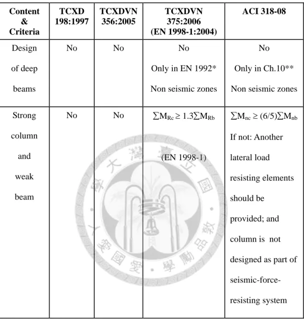
5.1 Deep beams in codes of Vietnam, Europe, U.S. ...137
5.2 Brief summary of design on deap beams ...138
in codes of Vietnam, Europe and U.S. 5.3 Deep beams and its problems ...139
5.4 Mode of failure with difference span-depth ratios [81] ...140
5.5 Mode of failure with difference width ratios [81] ...140
5.6 Comparison of results between proposed formulas ...141
based on box foundation analogy and FEM [82] 5.7 Earthquake records [85] ...141
5.8 Observed damage [85] ...141
5.9 Relationship between structural damage and story drift [85] ...142
5.10 Observed damage [86] ...142
5.11 Relationship between structural damage and story drift [86] ...142
5.12 Summary of maximum inter-story drift [86] ...143
5.13 Existing transfer structures in some regions in Vietnam ...143 A-1 Specimen No. 1/1.0N... A-1 A-2 Specimen No. 1/1.0S ... A-3 A-3 Specimen No. 2/1.0N... A-5 A-4 Specimen No. 2/1.0S ... A-7
LIST OF FIGURES
Figure No. Title Page
1.1 Seismic zonation map of Vietnam ...144
(TCXDVN 375:2006 Part 1[6]) 2.1 An example for reinforced concrete frame ...145
using wide beam-column connections 2.2 Wide beam-column connection, part of the beam longitudinal bars ...145
passed outside of the column core 2.3 Typical beam-column connections as beam width less than ...146
and equal column section width/depth 2.4 Typical wide beam-column connections ...146
2.5 Exterior joint: Anchoring of reinforcement in wide beam...147
2.6 Roof-corner joint: Anchoring of reinforcement in wide beam ...147
2.7 Plan view of connection of beam with core wall at expanded ...148
wall corner (a) and no fully expanded wall corner (b, c) 2.8 Beam-core wall joint at no expanded wall and layout of ...149
reinforcement in beam D1F3 2.9 Core wall and coupling beams: a) Plan view; ...150
b) Elevation for typical members 2.10 Reaction mechanism to lateral loads of (a) a coupled wall pier system ...150
and (b) an uncoupled wall pier system 2.11 Schematic of diagonal bars in coupling beams:...151
a) Detail in EN, ACI codes; b) Detail in TCXD 198:1997 [7] 2.12 Arrangement of diagonal bar in coupling beams ...152 a) without diagonal bars, b) with diagonal bars
2.13 Plan view of core wall and coupling beams (a) ...152
and section of coupling beams with diagonal reinforcement rods (b) 2.14 Coupling beams in drawing (a) and actual site (b): ...153
Diagonal cage becomes reinforcement rods 2.15 Anchoring bend of diagonal bars in coupling beams (dashed line)...153
2.16 Example of continuous deep beams (Elevated view) ...154
2.17 Guidance of detail for monolithic reinforced concrete ...155
frame in TCXD 198:1997 [7] 2.18 Using strut-and-tie models in single deep beams ...155
2.19 Structural plan with transfer beams ...156
2.20 3D view of analysis model with transfer beams in ETABS ...156
2.21 Photos of transfer beams during construction...157
2.22 Seismic zonation map of peak ground acceleration of China [21] ...158
2.23 Seismicity of the United States [22] ...158
2.24 Seismic hazard map for the Australia, South Pacific,...159
and Southeast Asia region [23] 2.25 European-Mediterranean seismic hazard map ...159
for the peak ground acceleration [24] 3.1 Additional measures for anchorage in exterior beam-column joints ...160
(Figure 5.13 in EN 1998-1:2004 [4]) 3.2 Confined boundary element of free-edge wall end...161
(Figure 5.8 in EN 1998-1:2004 [4]) 3.3 Detailing of confined boundary elements: a) Confined boundary ...161 element not needed at wall end with a large transverse flange;
b) Minimum thickness of confined boundary elements
(Figure 5.9, 5.10 in EN 1998-1:2004 [4])
3.4 Example of bearing: a) Detailing of reinforcement in support; ...162
b) Bearing with definitions (Figure 10.5, 10.6 in EN 1992-1-1:2004 [10]) 3.5 Maximum effective width of wide beam and required ...162
transverse reinforcement (Figure R21.5.1 in ACI 318-08 [2]) 3.6 Effective joint area (Figure R.21.7.4 in ACI 318-08 [2]) ...163
3.7 Bearing length on support (Figure R.16.6.2 in ACI 318-08 [2]) ...163
3.8 Different development length in codes ...164
3.9 Stirrup configurations in wide beam [43] ...165
3.10 Lateral load-displacement hysteretic loop ...166
4.1 Confinement of individual diagonals in coupling beams ...171
with diagonally oriented reinforcement (Figure 5.12 in EN 1998-1:2004 [4]) 4.2 Confinement of individual diagonals in coupling beams with ...171
diagonally oriented reinforcement (Figure R.21.9.7 in ACI 318-08 [2]) 4.3 Full confinement of diagonally reinforced concrete beam section ...172
in coupling beams with diagonally oriented reinforcement (Figure R.21.9.7 in ACI 318-08 [2]) 4.4 Coupling beams: 7 specimens for experimental test (l/h=3) [46]...173
4.5 Result of experimental tests for coupling beams [46] ...174
4.6 Coupling beams with slits and keyways [45] ...179
4.7 Proposed solution: Second option in ACI 318-08 [2]...179
(Figure R21.9.7.b) and Lequesne et al. [47] 5.1 Description for strut-and-tie models (case of single-span deep beams ...180
loaded with a concentrated load) (Figure RA.1.3 in ACI 318-08 [2]) 5.2 Two span continuous deep beams [61] ...180
a) Two span continuous deep beams under two point loading b) Truss model
5.3 Schematic STM for continuous deep beams based on ACI 318-05 [64] ...181
5.4 Crack pattern at failure [62]: a) Simple deep beam ...181
b) Two span deep beams 5.5 Span deep beams with bearing plates ...182
at loading and support locations [69] 5.6 Specimens of simple span and two span deep beams ...182
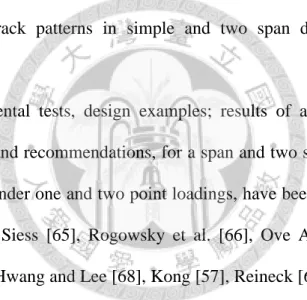
with column stubs [62] 5.7 Final crack patterns in 4 specimens [79]...183
5.8 Hysteretic curves: a) Beam CT; b) Beam CR [79] ...184
5.9 Shear force versus deflection curves for all beams...184
during positive loading [79] 5.10 Single span transfer beams-shear walls system [80]...185
5.11 Two span transfer beams-shear walls system [80] ...185
5.12 Typical transfer beams-coupled shear walls system [80] ...185
5.13 Typical transfer beams-frame system [80] ...186
5.14-Variation of cracking load with different span-depth ratios [81] ...186
5.15-Variation of failure load with different span-depth ratios [81]...186
5.16-Variation of cracking load with different width ratios [81]...187
5.17-Variation of failure load with different width ratios [81] ...187
5.18-Box foundation analogy [82] ...188
5.19-Rigid base analogy method [84] ...188
5.20-Grillage system method [84] ...188
5.21-Model of shaking table test [85] ...189
5.22-Mode of failure [85] ...189
5.23-Building with transfer plate [86] ...190
5.24-Experimental setup of test specimen [86]...190
5.25-Vertical displacements at the transfer plate ...190 when subjected to El-Centro Earthquakes [86]
A-1. Typical test series (Beam BM1 and BM2) ... A-9 A-2. Overall dimensions of specimens ... A-9 A-3. Detail of specimens... A-9 A-4. Geometry parameters of deep beams... A-10 A-5. Nodal types for checking ... A-10 A-6. Nodal zone for calculation of Acs, Anz... A-10
CHAPTER I INTRODUCTION
1.1 Brief on ACI 318-08 1.1.1 Brief on ACI
The American Concrete Institute (ACI) is the major agency for all concrete construction in the United States of America. It was established in 1904 to serve and represent user interests in the field of concrete. According to ACI-A Century of Progress [1], the history of an organization is a combination of events linking people, ideas, and activities. The ACI, and its predecessor, the National Association of Cement Users, were born of ideas-the concept that better concrete for more durable, maintenance-free structures is possible. The ACI reflects developments and knowledge within the concrete industry and the field of engineering, while at the same time influences those developments.
The ACI publishes many different standards, but the most commonly referenced standard used by architects and engineers is the ACI 318 [2] “Building Code Requirements for Structural Concrete.” It is updated continuously and the latest version is ACI 318-08 updated in 2008. Almost all building codes, including the IBC (International Building Code), refer to ACI 318 code as the basis for structural design of concrete members.
1.1.2 Brief on ACI 318-08
ACI 318-08 code includes: Introduction, 22 chapters and 5 appendixes:
Introduction
Chapter 1-General requirements
Chapter 2-Notation and definitions Chapter 3-Materials
Chapter 4-Durability requirements
Chapter 5-Concrete quality, mixing, and placing
Chapter 6-Formwork, embedments, and construction joints Chapter 7-Details of reinforcement
Chapter 8-Analysis and design-General considerations Chapter 9-Strength and serviceability requirements Chapter 10-Flexure and axial loads
Chapter 11-Shear and torsion
Chapter 12-Development and splices of reinforcement Chapter 13-Two-way slab systems
Chapter 14-Walls Chapter 15-Footings
Chapter 16-Precast concrete
Chapter 17-Composite concrete flexural members Chapter 18-Prestressed concrete
Chapter 19-Shells and folded plate members
Chapter 20-Strength evaluation of existing structures Chapter 21-Earthquake-resistant structures
Chapter 22-Structural plain concrete Appendix A-Strut-and-tie models
Appendix B-Alternative provisions for reinforced and prestressed concrete flexural and compression members
Appendix C-Alternative load and strength reduction factors
Appendix D-Anchoring to concrete
Appendix E-Steel reinforcement information
A chapter 21- Earthquake-resistant structure is focused to study in thesis.
1.2 Brief on EN and EN 1998-1:2004 1.2.1 Brief on EN
The EN Eurocodes describes the design method for buildings and civil engineering work. They consist of 10 different groups [3], which are:
EN 1990-Eurocode 0-Basis of structural design EN 1991-Eurocode 1-Actions on structures
EN 1992-Eurocode 2-Design of concrete structures EN 1993-Eurocode 3-Design of steel structures
EN 1994-Eurocode 4-Design of composite steel and concrete structures EN 1995-Eurocode 5-Design of timber structures
EN 1996-Eurocode 6-Design of masonry structures EN 1997-Eurocode 7-Geotechnical design
EN 1998-Eurocode 8-Design of structures for earthquake resistance EN 1999-Eurocode 9-Design of aluminum structures
Each Eurocode consists of several parts. There are 58 parts in all. The work with the Eurocodes started in 1975. The first publications came in the mid 80’s. By 2006 the EN Eurocodes Parts are expected to be published. By 2010 the Eurocodes are expected to be fully implemented and will replace all national codes. Some of the aims and benefits of the Eurocodes are to:
- Provide common design criteria and methods.
- Provide a common understanding of construction products.
- Facilitate the exchange of construction services.
- Be a common basis for research and development.
- Allow the preparation of common design aids and software.
- Increase the competitiveness of the European civil engineering firms, contractors, designers and product manufacturers in their world-wide activities.
Due to difficulties in harmonizing the calculation methods and level of safety, National Determined Parameters (NDP) has been included in the Eurocodes. The NDP’s can be found in a National Annex, which is a national standard and has to be applied in conjunction with the European standard.
The European Commission has supported, from the beginning, the elaboration of Eurocodes, and contributed to the funding of their drafting. It continues to support the task mandated to CEN to achieve the publication of EN Eurocodes. It will watch the implementation and use of the EN Eurocodes in the Member States. Table 1.1 will shows history overview of the creation of the Eurocodes.
1.2.2 Brief on EN 1998
EN 1998-Eurocode 8-Design of Structures for Earthquake Resistance includes 6 parts as following [3]:
EN 1998-1: Eurocode 8-Design of Structures for Earthquake Resistance-Part 1:
General rules, seismic actions and rules for buildings. Eurocode 8 applies to the design of buildings and civil engineering works in seismic regions. Its purpose is to ensure that in the event of earthquakes: Human lives are protected; damage is limited; and structures important for civil protection remain operational. EN 1998-1:2004 is EN 1998-1 Eurocode 8-Structures for Earthquake Resistance-Part 1: General rules, seismic actions and rules for buildings, its version is year of 2004.
EN 1998-2: Eurocode 8-Design of Structures for Earthquake Resistance-Part 2:
Bridges within the framework of the general requirements set forth in Part 1.1. This part of the code contains design principles, criteria and application rules applicable to the earthquake resistant design of bridges.
EN 1998-3: Eurocode 8-Design of Structures for Earthquake Resistance-Part 3:
Assessment and retrofitting of buildings. This document provides criteria for the evaluation of the seismic performance of existing individual building structures, and describes the approach in selecting necessary corrective measures.
EN 1998-4: Eurocode 8-Design of Structures for Earthquake Resistance-Part 4:
Silos, tanks and pipelines. This standard includes the additional criteria and rules required for the seismic design of this structure without restrictions on their size, structural types and other functional characteristics. For some types of tanks and silos, however, it also provides detailed methods of assessment and verification rules.
EN 1998-5: Eurocode 8-Design of Structures for Earthquake Resistance-Part 5:
Foundations, retaining structures and geotechnical aspects. This Part of Eurocode 8 establishes the requirements, criteria, and rules for siting and foundation soil of structures for earthquake resistance. It covers the design of different foundation systems, earth retaining structures and soil-structure interaction under seismic actions.
EN 1998-6: Eurocode 8-Design of Structures for Earthquake Resistance-Part 6:
Towers, masts and chimneys. This document deals with material related Eurocode parts dealing with towers, masts and chimneys. Design rules for the earthquake resistant design of tall, slender structures: Towers, including bell-towers, masts, industrial chimneys and lighthouses constructed in reinforced concrete or steel.
1.2.3 Brief on EN 1998-1:2004
EN 1998-1:2004 [4] is Eurocode 8-Design of Structures for Earthquake Resistance-Part 1: General rules, seismic actions and rules for buildings, and the latest version is EN 1998-1:2004 updated in 2004.
EN 1998-1:2004 includes 10 parts and 3 annexes:
1. General.
2. Performance requirements and compliance criteria 3. Ground conditions and seismic action
4. Design of buildings
5. Specific rules for concrete buildings 6. Specific rules for steel buildings
7. Specific rules for composite steel – concrete buildings 8. Specific rules for timber buildings
9. Specific rules for masonry buildings 10. Base isolation
Annex A (Informative) Elastic displacement response spectrum.
Annex B (Informative) Determination of the target displacement for nonlinear static (pushover) analysis.
Annex C (Normative) Design of the slab of steel-concrete composite beams at beam-column joints in moment resisting frames.
The EN 1998-1:2004-Structures for Earthquake Resistance-Part 1: General rules, seismic actions and rules for buildings, Section 5-Specific rules for concrete buildings, is focused to study in thesis.
1.3 Vietnam seismic risk
1.3.1 Earthquake situation in Vietnam
The report of Ministry of Construction of Vietnam [5]: According to Vietnam seismic zonation map as shown in Figure 1.1 in TCXDVN 375:2006-Part 1 [6], Vietnam has only a few areas of the Northern regions are predicted to be able to earthquake level VIII (MSK-64 scale). Shocks caused by earthquakes at some Northwest locations can reach level IX, also the majority of Vietnam's territory can occur, and the soil conditions are very weak. Thus, the earthquake happened in Vietnam is not strong intensity and the amount is not much compared to many parts of the world, usually ranging weak to moderate intensity. Frequency of earthquakes with occurred strong intensity is very low.
Results of the research and forecasting earthquakes in Vietnam, since 2005 show that year of 114 to 2003, with measurements or historical data, the earthquakes were recorded 1.645 with magnitude of over 3 Richter. The earthquake in Tuan Giao (Dien Bien province, Northwest of Vietnam) in 1983 with intensity of 6.8 Richter and the largest quake in Vietnam was recorded. In addition, there were also the earthquakes in 1935, 2001 with magnitude of 6.7-6.8 Richter ever happened in Dien Bien province.
The earthquakes have intensity from 4.6 to 4.8 Richter in other places: Bac Giang-1961, Son La-1983 and 2009, Dien Bien-2001 (Northern Vietnam), Nghe An- 2005 (South of Northern Vietnam).
Each code has difference classification for seismic intensity, Russian Federation:
MSK-64 scale, France: MM scale, United State of America (UBC-Uniform Building Code): Zones, Japan: JMA scale. Table 1.2 shows conversion between peak ground acceleration and earthquake intensity according to MSK-64 scale and MM scale.
1.3.2 Conclusions
Vietnam is located in low-to-moderate seismic regions if compared with some Asian countries like Japan, Taiwan, Indonesia, etc. Only some specific zones are located in strong seismic regions, like Dien Bien province in Northwest Vietnam.
In Vietnam, however, according to TCXDVN 375:2006-Part 1 [6], based on the design ground acceleration ag=IagR, design for earthquake-resistant structures is divided into three categories as following (Figure 1.1):
- ag≥0.08g (Strong seismicity): Shall be calculated and detailed for earthquake- resistant structures.
- 0.04gag<0.08g (Low seismicity): Reduced or simplified seismic design procedures for certain types or categories of structures may be used.
- ag<0.04g (Very low seismicity): The provisions of TCXDVN 375:2006 need not be observed.
where agR is determined from ground acceleration classification map of Vietnam (Appendix H, part 1, TCVN 375:2006-Part 1) or Table of ground acceleration classification according to administrative sites (Appendix I, part 1, TCXDVN 375:2006-Part 1).
1.4 Situations and difficulties in Vietnam’s civil engineering
1.4.1 Normative laws and regulations on technical standards for the earthquake prevention and resistance for structures
1.4.1.1 State’s legal documents:
Table 1.3 indicates the released time for legal documents in Vietnam’s civil and industry field. Before 1996, almost codes are used from former Soviet Union. From 1996 to 2004, only standards and codes of 7 countries and international organizations
have been adopted in Vietnam, such as: England, United State of America, Australia, Japan, ISO, etc. From 2005 to present, standards and codes from any countries, international organizations, regional codes organizations have been allowed in Vietnam according to requirements of Ministry of Construction (Vietnam).
1.4.1.2 Design standards of reinforced concrete structures for earthquake resistance
Design standards related to reinforced concrete structures and reinforced concrete structures in high rise buildings are
- TCVN 2737:1995 Load and action-Design standard (based on former Soviet Union).
- TCVN 5574:1991 Reinforced concrete structures-Design standard (former Soviet Union.
- TCXD 198:1997 [7] High rise building-Guide for design of monolithic reinforced concrete structures (former Soviet Union).
The provisions of calculation and design for reinforced concrete structures are used standards of former Soviet Union, in fact, main contents related earthquake resistance in TCXD 198:1997 is based on CHиП II-7-81* (Standards and Regulations for Construction, Chapter 7, Part II) of former Soviet Union.
Until years of 2005, 2006, Vietnam has issued three standards for the design of reinforced concrete structures is based on the standards of Russian Federation and Eurocodes:
- TCXDVN 356:2005 [8] Concrete and reinforced concrete structures-Design standard (Russian Federation).
- TCXDVN 375:2006 [6] Design of structures for earthquake resistance-Part 1:
General rules, seismic actions and rules for buildings (Eurocodes).
- TCXDVN 375:2006 Design of structures for earthquake resistance-Part 2:
Foundations, retaining structures and geotechnical aspects (Eurocodes).
TCXDVN 375:2006-Part 1 guided specific cases to consider the impact of earthquakes and measures earthquake resistant design for buildings. Accordingly, structures in low seismicity regions, when the ground acceleration based soil type A does not exceed 0.78 m/s2, it can use the design is subjected to mitigation earthquake or simplified for some categories, types of structures. For structures in the earthquake zones are very low, when the ground acceleration based soil type A does not exceed 0.39 m/s2, need not comply with the terms of this standard.
In which, Part 1 and Part 2 of TCXDVN 375:2006 were translated on the basic of EN 1998-1 and EN 1998-5 respectively, while TCXDVN 356:2005 [8] were translated on the basic of CHиП 2.03.01-84* of Russian Federation. Because of large difference gaps between TCXDVN 356:2005 and TCXDVN 375:2006, many local engineers do not know how to design comply with standards.
1.4.2 Observance of legal documents, technique standards for the prevention and resistance of earthquake
In Letter issued 2008 [5] by the Ministry of Construction of Vietnam, the situation of observance of legal documents, technique standards of earthquake prevention for construction projects in Vietnam in recent years has been not good.
At the stage construction period 1954-1976, with the structural solution of the reinforced concrete large panels were assembled forming the apartment zones with 1
through 5 stories. However, most of the projects are low building and not designed earthquake resistance.
At the period 1976-1986, in Northern Vietnam, almost houses with reinforced concrete large panels assembled. Some of them were calculated for earthquake resistance. Vietnam’s first building designed subject to earthquake load was 11 floors in Giang Vo-Hanoi capital (now is Hanoi Hotel). Most of the projects designed for earthquake resistance in the north of Vietnam. In the southern Vietnam, almost buildings were built previously not interested in earthquake resistance.
In the phase from 1986 to 1997, a number of foreign investment projects deployed in Vietnam. The high-rise buildings were designed for earthquake resistance.
In the construction phase from 1997 to present, the construction work was developed on the number, category and level of works. Vietnam has appeared more and more high rise buildings over 20 floors. Particularly in Hanoi, many high rise buildings using core wall slip solutions combined with assembled floors and columns. The projects are constructed according to this solution has disadvantages are difficult to control the quality for joints, so it to be limited in use. The projects under construction in Hanoi and elsewhere during this period are most designed for earthquake resistance at level VII (MSK-64 scale). The standards for earthquake resistance are applied mostly standards of the former Soviet Union and UBC (Uniform Building Code) of the United States of America.
Pursuant to the report of the Committee of Provinces and Cities directly under the Central Government (42/63 local reports), the construction works at the local before TCXDVN 375:2006 becomes effect, are not interested in earthquake resistant design, except in large cities like Hanoi (northern), Da Nang city (central), Ho Chi Minh city (southern), are done well.
1.4.3 Conclusions
(1) Generally, construction’s law and standards are not completed. Design standards for concrete and reinforced concrete structures is not consistent, currently still at the stage to continue shifting standards Eurocodes. It will take several years for Vietnam to have a full set of standards for design and construction of reinforced concrete structures.
(2) In the present, because of large difference gap between TCXDVN 356:2005 and TCXDVN 375:2006, many local engineers do not know how to design according to standards.
(3) In the past and also at the present, beside TCXDVN 375:2006-Part 1 (EN 1998-1) comes into effect, the design earthquake-resistant structures for the projects in Vietnam has mainly based on foreign standards such as CHиП II-7-81* of the former Soviet Union, the United States of America such as various versions of UBC-1985, UBC-1988, UBC-1991 and UBC-1997 [9]. By CHиП II-7-81* in accordance with the design standard system of Vietnam's current so designers often use more than other standards. The contents of the CHиП II-7-81* were also included in the design of earthquake resistance in TCXD 198:1997. The EN 1998-1 (TCXDVN 375:2006 Part 1) has been effected in 2006, due to inconsistency so that it was not used commonly. ACI 318 code has only been applied in Vietnam for some projects.
(4) Obviously, Vietnam has little experience in design for earthquake resistance.
Due to limited capacity should still exist a number of traffic works, irrigation, civil engineering... designed by local consultancy organization is not considered when designing earthquake resistance. Moreover, documents related new standards issued in 2005, 2006 has not been released, such as evaluation and strengthening the structures, and guiding detail for earthquake resistance.
(5) In the set of EN Eurocodes, Vietnam just compiled and put to use some parts in EN 1998. The rest of the Eurocodes are in its compilation. Particularly, EN 1992-1-1 [10] Eurocode 2-Design of Concrete Structures-Part 1-1: General Rule and Rules for Buildings, still does not adopt in Vietnam legally, it has unofficial document in Vietnamese [11], while EN 1998-1 has been adopted in Vietnam as name TCXDVN 375:2006-Part 1 [6]. At present, two guide books was released, first book [12] is used for TCXDVN 375:2006, and other one [13] is used for TCXDVN 356:2005. Therefore, it can say that engineers are currently had to use many other standards in earthquake- resistant design for the projects.
(6) For each standard, in addition to issuing the new standards will also need to change the entire textbook in universities and of course the whole curriculum, hold on research and training courses on contents of codes. This so far has not done so that it already makes many difficulties for Vietnamese engineers in designing, particularly earthquake-resistant design for structures.
(7) Since all of these reasons, EN 1998-1 is official in Vietnam but not implemented yet thorough and effective; ACI 318 code for earthquake-resistant structures is used rarely in Vietnam. There are some books about ACI 318 codes was released [14], [15]. If ACI code is applied then often using options are available in the software of analysis and design of structures such as SAP2000, ETABS, etc. These are limited of the author in this thesis.
(8) In addition, it can say that, like other developing countries, in civil engineering, economic and time factors would normally considered more than these technical factor, which as a general rule of development. This is a very difficult problem for engineers to execute the work under the provisions of the standard
.
CHAPTER II
TYPICAL CONSTRUCTION PROBLEMS FACED IN VIETNAM
2.1 Problem 1: Wide beam-column joints, beam-core wall joints
Beam-column joints and beam-core wall joints are an important part of a reinforced concrete moment resisting frame subjected to earthquake loading. Design and detailing provisions on beam-column joints and beam-core wall joints in wide beam cases in codes do not adequately address prevention of anchorage failure and shear failure in regions during other level earthquake shaking. In Vietnam, many high rise buildings used as offices, hotels, residential and commercial buildings are often designed with a beam whose width is larger than beam height, this beam is called wide beam with wide beam width is wider than column size. As required by the architecture, or in other words, economic factors, height of story is usually 3.3 m, rarely designed 3.6 meter or 3.9 meter in height. When it is needed big space to facilitate the function layout of project, the span of beam should pass greater than normal, such as column grid is greater than 8m. To handle this problem, there are many ways, such as pre-stressed beams, flat floor, etc. However, engineers often choose the safest way is reinforced concrete wide beams. For example, the height of the storey of 3.3 meter, the average height of beam is only about 0.4 through 0.5 meter to ensure clear spans and function of the building. For this beam height, in order to the beam can be passed a large span, for instance 8 meter, of course, it will be needed to expand the beam width to 1 meter or reach 1.5 meter. While the column size can not expand the area to equal with beam width, in many cases, only about 0.5 meter to 0.8 meter of column size is enough for strength resistant capacity of column. On contrary, in many cases, column size are
expanded to reach wide beam width due to structural designers do not know how to solve problems that the wide beam width is wider than column size.
Figure 2.1 shows an example of a reinforced concrete frame with the wide beam-column joints, and in connection types, the wide beam width is wider than column section, part of beam longitudinal reinforcements passes outside of the column core, as shown in Figure 2.2 (Gentry and Wight [16]). Comparing to the normal conditions is beam width is smaller columns section (Figure 2.3), in other word, all of beam section is located inside the column area, this problem has been indicated in the standards and codes. In the cases of the wide beam width is wider than the column size (Figure 2.4), the issues should be resolved is detailing of reinforced steels in wide beam which are passed outside of column core for joints of exterior and corner (Figure 2.4.b, c, e, f), especially for earthquake-resistant structures.
In the cases of the wide beam, some standard’s provisions are considered the effective wide beam width and the deviation between the center of columns and wide beams, but also needed to consider the issue of wide beam’s reinforced steel anchorage.
How to calculate and detail for reinforced bars that are outside of column area to ensure seismic resistance (Figure 2.5, 2.6), including top and bottom layers, in the load case of earthquake, the beam moment will be changed sign.
Beam-core wall joints will be designed normally as beam connects at intersection point between two walls, or wall section can be expanded as column to fit with beam (Figure 2.7.a). However, it is not always able to do so. In fact, there are many cases that beam connects to core wall at other positions as shown in Figure 2.7.b, 2.7.c, even above coupling beam. In such cases, the best way that let consider them as regular cases in Figure 2.7.a, it means that no any problems occur or there is nothing difference between connections in Figure 2.7.b and Figure 2.7.c.
Some engineers also solve the connection in Figure 2.7.b, 2.7.c by detailing of beam’s reinforcing bars in order to the joint between core wall and beam becomes hinge (Figure 2.8.c). The “hinge connection” in Figure 2.8.c will lead reinforcement ratio less than so much “rigid connection” in Figure 2.8.b in beam D1F3. Briefly, how to solve the joints in Figure 2.7.b, 2.7.c, and put the hinge at joint (Figure 2.8.c) is suitable or not, especially for design of earthquake-resistant structures.
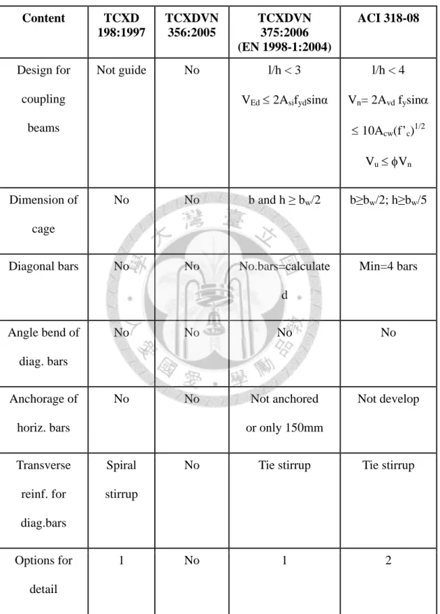
Table 2.1 illustrates status of problem 1 in 3 codes of Vietnam, Europe and United States of America.
Lastly, contents will be solved in this study:
(1) For the wide beam-column joints:
- Anchorage issues of wide beam’s reinforced bars passed outside of the column core in 4 typical joints: Exterior joint (Figure 2.4.b), corner joint (Figure 2.4.c), roof- exterior joint (Figure 2.4.e) and roof-corner joint (Figure 2.4.f).
- Related issues on design of wide beam-column joints.
(2) For the beam-core wall joints:
- Detailing issues of beam-core wall joints: Rigid or hinge connections.
- Related issues on design of beam-core wall joints: core wall size at connection (Figure 2.7.b), eccentric joints (Figure 2.7.c).
(3) The wide beam-column joints could be designed in seismic regions or not.
2.2 Problem 2: Coupling beams
According to Fortney [17], in high rise buildings, core wall and coupling beams are indispensable parts in the structural system resist lateral forces (Figure 2.9).
Coupling beams if properly reinforced to provide them with sufficient strength and stiffness, can increase the lateral stiffness of the building significantly. Lateral
deflection of walls induces large moments and shears in the coupling beams as they resist imposed deformations. Figure 2.10 illustrates the different mechanisms for resisting overturning moments for uncoupled wall piers and the coupled system.
Coupled and uncoupled systems act similarly in terms of resisting gravity loads; as illustrated in Figure 2.10, the difference between the two structures is realized only when resistance of lateral loads is considered. When the coupling beams over the height of the core wall system are proportioned appropriately to attain the desired behavior of the coupled core wall system, the coupling beams will form plastic hinges, in shear, simultaneously while going through very similar beam end rotations. This behavior results in a desirable distribution of energy dissipation (in the coupling beams) over the height of the building as opposed to the energy dissipation being concentrated at the base of the flexural wall piers. In order to achieve the desired behavior of the coupled core wall system, the coupling beams must be designed and proportioned for adequate stiffness and strength. However, the coupling beams must also yield prior to the wall piers and demonstrate stable hysteretic response and good energy-absorbing characteristics.
With actual conditions in Vietnam and as well as in other countries, ensuring quality of reinforced concrete core wall and the coupling beams, especially for positions linked between elements, such as core wall and beam, is not easy. In most cases, the ratio of reinforcement in the coupling beams and at joint of core wall with beam is so high.
Because of these difficulties, contractors and other responsibility engineers were free to change reinforcement ratio and position of reinforcing bars to more easily construct. It is so clearly wrong, but also that designer has product is not perfect. Figure 2.12, 2.13 and Figure 2.14 show the differences between codes (Figure 2.11.a and
2.11.b), drawing and actual site. There are also cases that engineers have to bend anchored development length for diagonal bars in the coupling beams by they are too long, difficult installation, steel congestion in wall, etc. (Figure 2.15). In fact, the issue of anchoring for diagonal reinforcements in the coupling beams also faces problem such as the development length exceeds concrete section of core wall. In this case, bend of diagonal bars with appropriate shapes are forced to anchor them into concrete section to ensure adequate anchored length of diagonal bars according to requirement of the standards (Figure 2.15). In addition, sometimes, the coupling beams are replaced by slabs in practice, due to requirements from architect or structural designer, or by contractor for easy to build. In order to ensure quality during construction at site, what matters to consider for the coupling beams are such as: The necessary of diagonal reinforcements, bending angle of diagonal reinforcements, and the coupling beams can be removed in some cases or not… Generally, the coupling beams have not been considered carefully in both stages of design and construction for high rise buildings in seismic regions. Many coupling beams had been became lintel beam in core wall in lateral loading resisting system by inadequacy understanding, a maijor reason is by Vietnamese standard. Table 2.1 also illustrates status of problem 2-coupling beams in 3 codes of Vietnam, Europe and United States of America.
Briefly, problems about the couppling beams are
(1) Necessitating the use of diagonal bars in the coupling beams, detailing diagonal bars and changing content of diagonal bars in the coupling beams.
(2) Discontinuity (cut off) diagonal bars at mid-span.
(3) Anchored bend of diagonal bars into core wall.
(4) Anchorage of horizontal bars.
(5) Drop of the coupling beams and replace by slab.
2.3 Problem 3: Deep beams in high rise buildings
Transfer structures are commonly used in the world, especially for regions of non-seismicity and low-to-moderate seismicity, such as Southeast Asia: Bangkok, Malaysia, Singapore, especially Hong Kong, and some regions in mainland China. This structure can be used for low rise and high rise buildings. Transfer structures can be designed as either shear or flexural members. Some types of transfer structures are deep beams, transfer girders, transfer plates, transfer beams, transfer boxes and transfer trusses.
In Vietnam, the concept of deep beams is usually only in materials of foreign country or textbooks that translated from other languages, Vietnamese engineers rarely use it in projects. Overseas firms have been often designed transfer structures as transfer beams, deep beams in high rise buildings. Categories of the deep beams are one span, continuous span as transfer girders, transfer beams (Figure 2.16, 2.17.b, 2.18 and 2.19).
In fact, projects using the transfer structures are not much in Vietnam. Some reasons to limit in using these structural types that are complexities of its design, ensuring quality in sites, and less experience. In Vietnam, projects using transfer structures often designed by foreign consultant company, or at least concept or preliminary design by foreign engineer, had problem due to congestion of steel in beam, resulting in concrete quality was to poor and it was solved again by using self-compacting concrete. Some transfer structures as deep beams, transfer beams and transfer plates are used in Vietnam such as Trung hoa-Nhan chinh, Golden Westlake (Hanoi), Mannor 2, The Everich, Hung Vuong plaza, Saigon Pearl, Kenton residences, Sailing Tower (Ho Chi Minh city), etc.
The calculations for transfer beams as flexural member (as conventional beam) or single deep beams are simple but rarely appearances in high rise buildings.
Otherwise, transfer beams as multiple span deep beams appear much more. When it has a standard form like theory or sample in some researches then problems can be solved by different ways of calculation, Figure 2.18 presented model of strut-and-tie method.
Nevertheless, the fact is that design of transfer beams is not easy as theory, Figure 2.19, 2.20 and Figure 2.21 present one example of transfer beams had been done in Vietnam, basic design by foreigner designer, and detail design by local consultant. The questions in complex cases are how to simplify, calculate, and detail not only for deep beams, but also for transfer structures, especially reinforcement ratio is much in the deep beams.
In strong seismicity regions, Vietnam is an example now, design of earthquake- resistant structure in high rise buildings, maybe need to consider to provisions for using the deep beams, transfer structures. It should be limited to design them in moderate to strong earthquake zones. Moreover, designer should be also selected simple and friend structural models to computer models in order to ensuring the safety factor for quite complex structural system. Table 2.1 illustrates status of problem 3-deep beams in 3 codes of Vietnam, Europe and United States of America.
In brief, issues will be solved in this thesis:
(1) Analytic model for complicated deep beams.
(2) Application of the transfer structures in seismic regions.
2.4 Seismic design category
The EN 1998-1:2004 provides the option to design reinforced concrete buildings for a combination of strength and ductility relationship by defining three alternatives ductility classes. Three dissipation classes are (Spathelf [18], Elghazouli [19]):
- Low (ductility class low (DCL)) in which virtually hysteretic ductility is intended and the resistance to earthquake loading is achieved through the strength of the structure rather than its ductility.
- Medium (DCM) in which quite high levels of plasticity are permitted and corresponding design and detailing requirements are imposed.
- High (DCH) where very large inelastic excursion are permitted accompanied by even ore onerous and complex design and detailing requirements.
For reinforced concrete buildings designed for low energy dissipation capacity and low ductility (DCL), no specific seismic detailing requirements have to be met. Clause 5.2.1(2)P (EN 1998-1:2004) said that concrete buildings may alternatively be designed for low dissipation capacity and low ductility, by applying only the rules of EN 1992-1- 1:2004 [10]. For buildings which are not base-isolated, design with this alternative, termed ductility class L (low), is recommended only in low seismicity cases. According to Clause 5.3.1, seismic design for DCL, following EN 1992-1-1:2004, without any additional requirement, except provision on use of reinforcing steel class in primary seismic elements, is recommended only for low seismicity cases. In contrast, structures designed for relatively high energy dissipation and overall ductile behavior are classified into two ductility classes, namely DCM and DCH, depending on the hysteretic dissipation capacity. Specific earthquake-resistant detailing provisions apply to both of these ductility classes, enabling the structure to dissipate hysteretic energy under repeated reversed loading without developing brittle failure modes. Both DCM and DCH are presented by the behavior factor q, and q depends on structural types, such as frame system, dual system (frame or wall equivalent), ductile wall system (coupled or uncoupled), system of large lightly reinforced walls, inverted pendulum system, torsion flexible system.
ACI 318-08 requires that all structures shall be assigned to a seismic design category (SDC), including 6 classes of SDC: A, B, C, D, E, F. SDC A, B corresponds to the lowest seismic hazard, SDC C may be subjected to moderately strong ground shacking, and structures assigned to SDC D, E, or F may be subjected to strong ground shacking. And it is the intent of Committee 318 that the seismic-force-resisting system of structural concrete buildings assigned to SDC D, E or F be provided be special moment frames, special structural walls, or a combination of the two. The ACI 318-08 also presented correlation table between ACI 318-08 and other codes with UBC-1997 [9] about seismic design categories and seismic zones (Table 2.2). Table also shows comparison between 3 codes ACI 318-08, EN 1998-1:2004 and TCXDVN 375:2006 Part 1 on seismic design category and seismicity regions.
Table 2.4 also describes diagram of seismic zonation map in three codes and standards of Social Republic of Vietnam, United States of America, and People’s Republic of China (Su [20], Tsang [21]). China’s seismic map is shown in Figure 2.22 (Tsang [21]) for return period 475 years (more than a 10% probability of exceedance in 50 years). The seismicity map of the United States as shown in Figure 2.23 (Lorant [22]), UBC-1997 seismic provisions contain six seismic zones, ranging from 0 to 4, equivalents to peak ground acceleration ranging from 0 to 0.4g. Figure 2.24 (McCue [23]) shows seismic hazard map for the Australia, South Pacific and Southeast Asia region with peak ground acceleration for an exceeded probability of 10% within 50 years (in other words, for a return period of 500 years). Figure 2.25 (Solomos et al. [24]) also shows European-Mediterranean seismic hazard map for the peak ground acceleration with 10% probability of exceedance in 50 years under stiff soil condition.
It seems to be that provisions for Vietnamese seismic region classification based on EN 1998-1:2004 are higher than other codes and practising earthquake in Vietnam.
Some countries of Southeast Asia like Singapore, Malaysia, and including Indonesia except Sumatra Island, are only located in low-to-moderate seismicity regions.
Additionally, Table 2.3 showed clearly about problem: SDC D, E, F (ACI 318-08) equivalents to DCM, DCH (TCXDVN 375:2006 Part 1) and SCD D, E, F also corresponded Seismic zone 3, 4 (UBC-1997) with PGA (peak ground acceleration) 0.3g. It means that the current Vietnamese seismic design code should be considered carefully in future. In Vietnam, author would like to recommend using 0.05gag<0.2g for low-to-moderate seismicity regions to replace current equivalent provisions in TCXDVN 375:2006-Part 1 as shown in Table 2.5. It leads to the use of ductility class low (DCL) for seismic design and detail in reinforced concrete buildings is allowed in low-to-moderate seismicity regions for many sites in Vietnam (Table 2.6). According to current seismic code, too many regions are located in strong seismicity regions by requirement of ag0.08g. Table 2.7 will summaries of correlation between standards and codes of United Stated of America, Europe and Vietnam on seismic design requirements to seismic zones and gives recommendation on current Vietnam’s standard. Obviously, two proposed solutions seem to meet some codes like P.R.China, United States of America, some countries in Southeast Asia, and not only for current practice on earthquake, but also for Vietnam’s history on practising earthquakes. This proposed recommendation will be illustrated and proved clearly and fully in next chapters on problems of wide beam-column connections and transfer structures, transfer beams in Vietnam.
CHAPTER III
WIDE BEAM-COLUMN JOINTS AND BEAM-CORE WALL JOINTS
3.1 EN 1998-1:2004
For the development length: EN 1992-1-1:2004 [10], Section 8 applies in EN 1998-1:2004 [4], the design anchorage length of longitudinal reinforcement, lbd, is (Clause 8.4.4(1)):
lbd = α1 α2 α3 α4 α5 lb,rqd ≥ lb,min (3-1) The basic required anchorage length, lb,rqd, for anchoring the force Asσsd in a straight bar assuming constant bond stress equal to fbd follows from:
lb,rqd = (/4) (σsd/fbd) (3-2) The design value of the ultimate bond stress, fbd, for ribbed bars, is:
fbd = 2.25η1η2fctd (3-3) The minimum anchorage length if no other limitation is applied, lb,min, are:
- For anchorages in tension:
lb,min > max{0.3lb,rqd; 10; 100 mm} (3-4)
- For anchorages in compression:
lb,min > max{0.6lb,rqd; 10; 100 mm} (3-5)
where: α1, α2, α3, α4 and α5 are coefficients given in table in EN 1992-1-1:2004 α1 is for the effect of the form of the bars assuming adequate cover.
α2 is for the effect of concrete minimum cover.
α3 is for the effect of confinement by transverse reinforcement
α4 is for the influence of one or more welded transverse bars (t>0.6) along the design anchorage length lbd.
α5 is for the effect of the pressure transverse to the plane of splitting along the design anchorage length.
σsd is the design stress of the bar at the position from where the anchorage is measured from.
fctd is the design value of concrete tensile strength.
η1 is a coefficient related to the quality of the bond condition and the position of the bar during concreting.
η2 is related to the bar diameter.
φ is diameter of a reinforcing.
For the detailing of anchorage of reinforcement in the earthquake resistance design, EN 1992-1-1:2004, Section 8, with the additional rules of the following below clauses apply (EN 1998-1:2004, Clause 5.6.1(1)P).
About geometric constraints, Clause 5.4.1.2.1(3)P is “To take advantage of the favourable effect of column compression on the bond of horizontal bars passing through the joint, the width bw of a primary seismic beam shall satisfy the following expression:
bw min {bc + hw; 2bc} (3-6) where hw is the depth of the beam and bc is the largest cross-sectional dimension of the column normal to the longitudinal axis of the beam.”
According to Equation (3-6), the beam width can be larger than the column section, twice the column dimension, it is used to design for both DCM, DCH (5.5.1.2.1(5)P). Regardless of anchorage of reinforcement, Clause 5.6.2.2(1)P is “The part of beam longitudinal reinforcement bent in joints for anchorage shall always be placed inside the corresponding column hoops.”
EN 1998-1:2004 indicates three measures if the development length cannot satisfied in exterior beam-column joints because the depth of the column parallel to the bars is too shallow, to ensure anchorage of the longitudinal reinforcement of beams:
a) The beam or slab may be extended horizontally in the form of exterior stubs (Figure 3.1.a).
b) Headed bars or anchorage plates welded to the end of the bars may be used (Figure 3.1.b).
c) Bends with a minimum length of 10dbl and transverse reinforcement placed tightly inside the bend of the bars may be added (Figure 3.1.c).
For the beam-core wall joints in Figure 2.7.b, 2.7.c, the Figure 3.2, 3.3 indicate the some cases of detailing for the wall provided in EN 1998-1:2004. Therefore, joints in Figure 2.7 can be computed in accordance with provisions in EN 1998-1:2004. The width of core wall in Figure 2.7.b is seem to be too small to support two wide beams at connection and not enough space to detail reinforcement for both the wall and the wide beam. However, core wall in Figure 2.7.a, 2.7.c has been detailed as a column at the corner and at the end of the wall, but only half part of the wide beam is inside column section in Figure 2.7.b. The joint in Figure 2.7.c is likely same the beam-column corner joint in Figure 2.4.c, except not the wide beam in other direction.
Regardless of effective joint width, Clause 5.5.2.3(1)P requires “The horizontal shear acting on the core of a joint between primary seismic beams and columns shall be determined taking into account the most adverse conditions under seismic actions, i.e.
capacity design conditions for the beams framing into the joint and the lowest compatible values of shear forces in the other framing elements.” For the exterior beam-
column joints, simplified expressions for the horizontal shear force acting on the concrete core of the joints, Vjhd, may be used as follows:
Vjhd = RdAs1fyd - VC (3-7) where: As1 is the area of the beam top reinforcement;
VC is the shear force in the column above the joint, from the analysis in the seismic design situation;
γRd is a factor to account for overstrength due to steel strain-hardening and should be not less than 1.2.
Clause 5.5.3.3(1)P requires “The diagonal compression induced in the joint by the diagonal strut mechanism shall not exceed the compressive strength of concrete in the presence of transverse tensile strains”, in the absence of a more precise model, this requirement may be satisfied by means of the subsequent rule: for at exterior beam- column joints:
Vjhd 0.8fcdbjhjc (1-d/)1/2 (3-8) where: η is degree of connection, η = 0.6(1-fck/250), fck is given in MPa;
hjc is the distance between extreme layers of column reinforcement;
d is the normalized axial force in the column above the joint.
bj is the effective joint width, if bc < bw (for mentioned case with wide beam):
bj = min [bw; (bc + 0.5hc)] (3-9) bj if bc > bw: See detail in EN 1998-1:2004 [4].
The problems of switch from rigid to hinge connection (Figure 2.8.b, 2.8.c), this joint becomes connections transmitting shear forces (Clause 10.9.4.4, EN 1992-1- 1:2004). For shear transfer in interfaces between two concretes, the shear stress at the
interface between concrete cast at different times should also satisfy the provisions 6.2.1 through 6.2.5 in EN 1992-1-1:2004. It is recommended when in the absence of more detailed information surfaces may be classified as very smooth, smooth, rough or indented, c and µ are factors which depend on the roughness of the interface:
- Very smooth: a surface cast against steel, plastic or specially prepared wooden moulds: c=0.25 and µ=0.5.
- Smooth: a slipformed or extruded surface, or a free surface left without further treatment after vibration: c=0.35 and µ=0.6.
- Rough: a surface with at least 3 mm roughness at about 40 mm spacing, achieved by raking, exposing of aggregate or other methods giving an equivalent behaviour: c=0.45 and µ=0.7.
In addition, the anchorage of reinforcement at supports is followed (Clause 10.9.4.7, EN 1992-1-1:2004): Reinforcement in supporting and supported members should be detailed to ensure anchorage in the respective node, allowing for deviations.
The effective bearing length a1 is controlled by a distance d from the edge of the respective elements where (Figure 3.4):
di = ci + Δai with horizontal loops or otherwise end anchored bars.
di = ci + Δai + ri with vertically bent bars.
where: ci is concrete cover, Δai is a deviation, ri is the bend radius.
3.2. ACI 318-08
In flexural members of special moment frames, geometric constraints of beam is provided in Clause 21.5.1.4: “Width of member, bw, shall not exceed width of supporting member, c2, plus a distance on each side of supporting member equal to the smaller of (a) and (b):

![Table 1.1-Short history overview of the creation of the Eurocodes [3]](https://thumb-ap.123doks.com/thumbv2/9libinfo/9604968.631090/122.892.127.756.163.1139/table-short-history-overview-creation-eurocodes.webp)
![Table 3.2-Main contents for design and detailing of wide beam-column connections No. Content TCXDVN 356:2005 [8] and TCXD 198:1997 [7] (CHиП 2.03.01-84* and CHиП II-7-81*) EN 1998-1:2008 [4] (TCXDVN 375:2006 [6]) ACI 318-08 [2] and ACI 352R-02 [](https://thumb-ap.123doks.com/thumbv2/9libinfo/9604968.631090/131.1263.106.1153.165.768/contents-detailing-connections-content-tcxdvn-chип-chип-tcxdvn.webp)
![Table 5.6-Comparison of results between proposed formulas based on box foundation analogy and FEM [81]](https://thumb-ap.123doks.com/thumbv2/9libinfo/9604968.631090/157.892.183.710.212.408/table-comparison-results-proposed-formulas-based-foundation-analogy.webp)
![Figure 1.1-Seismic zonation map of Vietnam (TCXDVN 375:2006-Part 1 [6])](https://thumb-ap.123doks.com/thumbv2/9libinfo/9604968.631090/160.892.197.707.137.1056/figure-seismic-zonation-map-vietnam-tcxdvn.webp)
