國立陽明交通大學 網路工程研究所
碩士論文
Institute of Network Engineering
National Yang Ming Chiao Tung University Master thesis
VerificationTalk:物聯網應用之正確性驗證系統 VerificationTalk: Verification of IoT Applications
研究生:許尹睿 (Hsu, Yin-Jui) 指導教授:林一平 (Lin, Yi-Bing)
謝旻錚 (Shieh, Min-Zheng)
中華民國一一〇年七月
July 2021
VerificationTalk:物聯網應用之正確性驗證系統 VerificationTalk: Verification of IoT Applications
研 究 生:許尹睿 Student:Yin-Jui Hsu 指導教授:林一平 教授 Advisors:Yi-Bing Lin 謝旻錚 教授 Min-Zheng Shieh
國立陽明交通大學 網路工程研究所
碩士論文
A Thesis
Submitted to Institute of Network Engineering College of Computer Science
National Yang Ming Chiao Tung University in partial Fulfillment of the Requirements
for the Degree of Master
in
Computer Science and Engineering
July 2021
Taiwan, Republic of China
中華民國一一〇年七月
i
VerificationTalk: 物聯網應用之正確性驗證系統
學生:許尹睿 指導教授:林一平 教授
謝旻錚 教授
國立陽明交通大學網路工程研究所碩士班
摘 要
IoTtalk 等圖形化物聯網裝置管理平台的核心是圖形化的使用者介面(GUI),它可以 簡單地描述物聯網裝置間的互動。物聯網應用程式能夠通過拖放裝置並指定它們間的資
料流來建立。IoTtalk 還提供了接點函數的功能,可以針對在物聯網裝置間傳輸的數據
進行一系列操作及運算。儘管 IoTtalk 提供開發物聯網應用的靈活性,但使用者的錯誤
部署(像是連接一些不該有任何資料流的裝置,或是在接點函數上執行錯誤操作,進而
影響資料傳輸的穩定性)可能會讓已開發的物聯網應用的可信賴性大打折扣。本篇論文
提出了名為 VerificationTalk 的物聯網應用驗證系統,以防止使用者的部署錯誤。
VerificationTalk 有兩個子系統:BigraphTalk 和 AFLtalk,分別負責驗證物聯網應用的
配置和接點函數。VerificationTalk 還提供執行時即時監控器的機制,能夠及時發現異常
資料。當 VerificationTalk 偵測到部署錯誤時,使用者可以使用它提供的回饋資訊進行
校正。本篇論文的目的為展示使用者如何使用 VerificationTalk 所提供的驗證機制,以
及 VerificationTalk 如何將驗證結果回饋給使用者。本篇論文還評估了 VerificationTalk 的效能,並根據實驗結果保證其效能突出。
關鍵字:物聯網、形式方法、雙圖模型、軟體測試、模糊測試、執行時即時監控器
ii
VerificationTalk: Verification of IoT Applications
Student:Yin-Jui Hsu Advisor:Prof. Yi-Bing Lin Prof. Min-Zheng Shieh
Institute of Network Engineering, National Yang Ming Chiao Tung University
Abstract
At the heart of graphical IoT device management platforms, such as IoTtalk, is a graphical user interface (GUI), which makes it easy to describe interactions between IoT devices. IoT applications are defined by dragging-and-dropping devices and specifying how they are connected. IoTtalk also provides join functions, which can perform some operations on the data transmitted between IoT devices. While IoTtalk is flexible enough to develop a wide range of applications, it often allows too much flexibility, making users possible to connect some devices that should never be linked and perform wrong operations on join functions. We propose VerificationTalk, which provides a comprehensive verification procedure, to prevent users from inappropriate deployments. The VerificationTalk has two subsystems: BigraphTalk and AFLTalk, which are responsible for verifying configuration and join functions, respectively. The VerificationTalk also provides the function of runtime monitor to detect the anomaly timely. As VerificationTalk detects the error, the users can use the feedback from it for debugging. This thesis aims to show how users use the verification mechanisms, and how VerificationTalk displays the verification result. This thesis also evaluates the performance of VerificationTalk and guarantees it performs well.
Keywords: Internet of Things(IoT), Formal Methods, Bigraph Models, Software Testing, Fuzz Testing, Runtime Monitor
iii
誌 謝
兩年的研究所生涯,讓我提升了專業能力及生活視野,完成碩士論文的這段期間,
獲得了許多人的協助,感激這些人的協助,在此獻上最大的敬意。
首先感謝林一平教授提供良好的研究環境和資源,並不厭其煩地指導、鞭策,讓我 在碩士生涯能夠朝著明確的方向前進。林一平教授在資訊工程領域達到的成就也讓我十 分敬佩,期許自己能以林一平教授為榜樣,在未來職場為這個社會做出貢獻。感謝共同 指導教授謝旻錚教授,在我的研究遇到瓶頸時,能夠在各方面給予我許多的意見及幫助,
點出問題的核心並提點正確的解決方式,讓我的研究能夠順利地進行,並在過程中累積 許多寶貴的經驗。且於學務繁忙之際,仍撥冗審閱我的論文,惠賜寶貴的意見,使我的 論文能更臻充實及完整,在此謹致上最崇敬的謝意。
感謝泰翔學長、峻頤學長、振淇學長給予許多系統架構及程式設計上的指點,在我 實作遇到問題時,總是不吝給予協助,並處理許多實驗室的繁瑣事務,讓我們這些學弟 妹沒有顧慮,能夠全心投入研究。感謝大賢學長、俊凱學長協助我熟悉實驗室的職務,
並在生活上給予許多實用的建議。感謝柏勛同學、昀諠同學、子翔同學及冠文同學陪我 一起從事閒暇之餘的休閒娛樂,並與我討論生活中的煩惱,讓我的碩士生活更加有趣且 順利。感謝我的家人及易蓉學妹的鼓勵與支持,謝謝你們成為我最大的動力和精神支柱,
讓我能在完全沒有後顧之憂的情況下,順利地完成論文。
最後,祝福實驗室的學長姊、同學與學弟妹都研究順利、身體健康,有個光明的未 來!
許尹睿 於 國立陽明交通大學網路工程研究所
中華民國 一一〇年七月
iv
Contents
摘要 ... i
Abstract ... ii
誌謝 ... iii
Contents ... iv
List of Tables ... vi
List of Figures ... vii
CHAPTER 1. Introduction ... 1
Section 1.1 Related Work ... 2
Section 1.2 VerificationTalk ... 4
CHAPTER 2. Architecture ... 6
Section 2.1 The IoTtalk Architecture ... 6
Section 2.2 The VerificationTalk Architecture ... 8
CHAPTER 3. BigraphTalk and Runtime Monitor ... 11
Section 3.1 Overview of the Bigraphs ... 11
Section 3.2 Configuration Verification ... 12
3.2.1 Modeling IoTtalk with Bigraphs ... 13
3.2.2 Detecting Forbidden Configurations ... 16
3.2.3 Feedback from Verification Result ... 17
Section 3.3 Forbidden Configuration Management Page ... 17
Section 3.4 The Database System of BigraphTalk ... 19
3.4.1 The ForbiddenConfiguration Table ... 22
3.4.2 The ForbiddenFeature Table ... 23
v
Section 3.5 Forbidden Configuration Management Procedures ... 24
3.5.1 create_forbidden_configuration() ... 24
3.5.2 get_forbidden_configuration_info() ... 27
Section 3.6 The Runtime Monitor Implementation ... 28
3.6.1 Logging Service ... 31
3.6.2 Performance of Runtime Monitor ... 31
CHAPTER 4. AFLTalk ... 35
Section 4.1 Overview of the American Fuzzy Lop (AFL) ... 35
Section 4.2 Join Functions Verification ... 37
4.2.1 Workflow for Testing Join Functions ... 40
4.2.2 Feedback from Testing Result ... 41
Section 4.3 Performance of AFLTalk ... 42
CHAPTER 5. Conclusion ... 47
Section 5.1 Future Work ... 47
REFERENCE ... 49
APPENDIX A. VerificationTalk Installation Guide ... 54
APPENDIX B. Format of Message from IoTtalk to BigraphTalk ... 58
APPENDIX C. Format of Message from BigraphTalk to IoTtalk ... 61
APPENDIX D. Forbidden Configuration Management Procedures ... 62
APPENDIX E. Format of Message from IoTtalk to AFLTalk ... 63
APPENDIX F. Format of Message from AFLTalk to IoTtalk ... 65
APPENDIX G. Generation of Synthetic Join Functions ... 66
vi
List of Tables
Table 3.1 BigraphTalk entities. ... 14
Table 3.2 The ForbiddenConfiguration Table. ... 22
Table 3.3 The ForbiddenFeature Table. ... 23
Table 4.1 Full Code Coverage Time as the number of prime paths are increased. ... 45
Table D.1 Forbidden Configuration Management Procedures. ... 62
vii
List of Figures
Figure 1.1 Instance of forbidden configuration. ... 2
Figure 2.1 The IoTtalk architecture. ... 6
Figure 2.2 The VerificationTalk architecture. ... 8
Figure 3.1 Instance of bigraph. ... 12
Figure 3.2 An instance of forbidden configuration involving multiple devices. ... 12
Figure 3.3 An instance of potential forbidden configuration. ... 13
Figure 3.4 Navigation bar of IoTtalk GUI. ... 13
Figure 3.5 Verification Settings Page. ... 14
Figure 3.6 The equivalent bigraph model of IoTtalk application. ... 15
Figure 3.7 Forbidden configuration predicate. ... 16
Figure 3.8 Potential forbidden configuration predicate. ... 16
Figure 3.9 Forbidden configuration highlighted in red. ... 17
Figure 3.10 Potential forbidden configuration highlighted in yellow. ... 17
Figure 3.11 Forbidden Configuration Management Page. ... 18
Figure 3.12 Create or modify the forbidden configuration. ... 18
Figure 3.13 Name the forbidden configuration. ... 19
Figure 3.14 The Database system of BigraphTalk. ... 20
Figure 3.15 The Python code for the BigraphTalk Event Handler to initialize the BigraphTalk DB. .... 21
Figure 3.16 The Python class for the ForbiddenConfiguration Table. ... 23
Figure 3.17 The Python class for the ForbiddenFeature Table. ... 24
Figure 3.18 The HTTP message to create the Curtain forbidden configuration. ... 25
Figure 3.19 The Python code for create_forbidden_configuration(). ... 26
viii
Figure 3.20 The Python code for get_forbidden_configuration_info(). ... 28
Figure 3.21 IoTtalk GUI displaying the verification result. ... 28
Figure 3.22 Detect a potential error through Runtime Monitor. ... 29
Figure 3.23 The Python code of rule function. ... 29
Figure 3.24 Runtime Monitor intercepts invalid data. ... 30
Figure 3.25 Dialog window displaying the error message related to invalid data. ... 30
Figure 3.26 Instance of logging service record. ... 31
Figure 3.27 Distribution of delay when the Runtime Monitor is on/off. ... 32
Figure 3.28 An instance of synthetic IoTtalk application. ... 33
Figure 3.29 Delay as the number of potential forbidden configurations are increased. ... 34
Figure 4.1 Flowchart of AFL algorithm. ... 36
Figure 4.2 IoTtalk configuration of AgriTalk. ... 38
Figure 4.3 The Python code for join function n-demand. ... 38
Figure 4.4 An instance of erroneous join function. ... 39
Figure 4.5 IoTtalk configuration of FrameTalk ... 40
Figure 4.6 Target/Results Storage architecture. ... 41
Figure 4.7 Dialog window displaying the error message related to join functions. ... 42
Figure 4.8 Control-flow graph of join function n-demand. ... 43
Figure 4.9 Comparison between the traditional approach and the IoTtalk approach. ... 45
Figure 4.10 Average-Max-Min chart of full code coverage time. ... 46
Figure A.1 Configuration File config.py of VerificationTalk Subsystem. ... 56
Figure A.2 Service Definition YAML File docker-compose.yml of IoTtalk Server. ... 57
Figure B.1 JSON object sent from IoTtalk to BigraphTalk. ... 60
ix
Figure C.1 JSON object sent from BigraphTalk to IoTtalk. ... 61
Figure E.1 JSON object sent from IoTtalk to AFLtalk. ... 64
Figure F.1 JSON object returned from AFLtalk to IoTtalk. ... 65
Figure G.1 An instance of synthetic function that is extracted from a native function. ... 66
Figure G.2 The Python code for random_choice_csc(). ... 68
Figure G.3 An instance of synthetic function that is assembled from the native functions. 68 Figure G.4 The Python code for sparse_min_max(). ... 68
Figure G.5 The Python code for sparse_nan_min_max(). ... 69
1
Introduction
In recent years, the Internet of Things (IoT) applications increase rapidly and expand to many sectors [1]. With the rise of next-generation mobile network 5G, IoT has a promising future in daily activities, medical needs, and prevention of harmful eventualities. From this, IoT is a growing field, and it would continue to grow substantially in the years to come.
Unfortunately, creating IoT applications can be challenging, often relying on detailed knowledge of low-level protocols used for machine-to-machine communications. Therefore, several device integration and management systems [2] [3] have been proposed to abstract over low-level protocols and are essential to allow both novice and advanced users to benefit from the increasing availability of IoT hardware. Here we focus on one existing platform called IoTtalk [3] [4] [5], which supports the rapid development of network applications to drive the sensors and the actuators.
In IoTtalk, an IoT application is designed such that the IoT devices and network applications are modularized for conveniently reused through the graphical user interface (GUI). Therefore, users are allowed to drag-and-drop devices, each containing a set of input and output device features. Device Features can then be graphically linked via joins to create an application. IoTtalk also provides join functions on these joins, implementing data transformation and decision logic on the data transmitted between IoT devices.
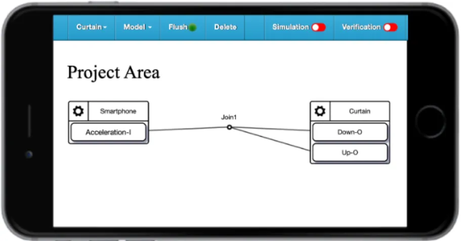
While IoTtalk is flexible enough to develop a wide range of applications, it often offers too much flexibility. Users may connect some devices that should never have any connection or perform wrong operations on the join function, which may provide limited guarantees of their deployment behavior. For example, a curtain cannot move up and down simultaneously (see Fig. 1.1). As each actuator receives the same value, they will attempt to drive the motor in different directions, potentially leading to hardware damage. We call such errors as
forbidden configuration, which may cause incorrect or inefficient applications, as well as
potential hardware damage [6].2
Figure 1.1 Instance of forbidden configuration.
To prevent users from creating invalid configurations of devices, we propose a formal verification approach for IoTtalk. It utilizes the bigraph models [7] and guarantees the deployed application’s correctness. Besides, we also adopt American Fuzzy Lop (AFL) [8], an excellent gray-box fuzzing tool, to prevent performing inappropriate operations in join functions. This chapter first describes the related work and then provides our ideas on how to integrate these verification tools.
Related Work
In this section, we will briefly introduce the following tools related to the verification of IoTtalk applications.
In computer science, formal methods [9] are a particular kind of mathematically rigorous techniques for the specification, development, and verification of software and hardware systems. Among the purposes mentioned above, formal verification uses software tools to prove the properties of a formal specification, including whether a formal model of a system implementation satisfies its specification. Bigraphs, a formal model used for verification, were first introduced by Robin Milner [7] as a universal mathematical model for representing the spatial configuration of physical or virtual objects, their interaction capabilities, and temporal evolution [10]. A bigraph is a pair of relations over the same set of nodes: a directed forest, called place graph, representing topological space in terms of node containment and a hypergraph, called link graph, representing the interactions and non-spatial relations among
3
nodes [10]. The system based on bigraphs is called Bigraphical Reactive System, a universal formalism for modeling interacting systems that evolve in time and space. It has been applied to model a wide range of systems such as IoT/Edge systems [10] and MixedReality systems [11]. Although existing tools, such as those based on UML [12], have basic support to express the safe connection of components, bigraphs are an expressive computational model, which has proved useful [10] [11] to increase the readability and ease of extension of models by providing an intuitive graphical notation.
However, the formal methods are not a panacea. Checking whether a join function terminates for all inputs, which is an instance of the undecidable problems [13], is one of the issues formal methods cannot solve. Therefore, we adopt an efficient software testing technology called fuzz testing to make up for this deficiency.
Fuzz testing has become one of the most effective testing techniques for finding correctness [14] and security issues in software systems, such as memory corruption vulnerabilities and numeric errors. The goal of fuzz testing is to run the program into as many paths as much as possible. In this manner, we can soon find out an input that crashes or hangs the program if such input exists. In practice, testers have found many errors in accuracy and security risks in widely used software [15] [16]. Since IoT devices usually have resource limitations and are prone to compromise, an effective way of promoting IoT security at a low cost is removing program vulnerabilities, and fuzz testing is a promising technique that exposes bugs in IoT programs. Accordingly, fuzz testing has been adopted to detect the vulnerabilities in IoT devices [17] [18] and IoT applications [19].
As a security-oriented fuzzer, American Fuzzy Lop [8] has attracted attention in both practice and research [15]. The American Fuzzy Lop employs a novel type of compile-time instrumentation and genetic algorithms to automatically discover clean, interesting test cases that trigger new internal states in the targeted binary. This approach substantially improves the functional coverage for the fuzzed code. Previous studies [20] and [21] show that the extension of AFL has been successfully applied to the field of IoT and can automatically find vulnerabilities in real-world IoT programs efficiently.
4
VerificationTalk
In this thesis, we propose an IoTtalk applications correctness verification system called VerificationTalk to provide a comprehensive verification procedure that can prevent the erroneous deployment caused by users in advance. To support the verification of IoTtalk applications, VerificationTalk is developed on top of IoTtalk [3] [4] [5], an IoT system supporting the rapid development of network applications to drive the newly created sensors.
The VerificationTalk consists of two components: BigraphTalk [6] and AFLtalk.
BigraphTalk is responsible for checking whether users connect some devices that should never have any connection, and AFLtalk can prevent users from performing wrong operations on join functions. In addition, VerificationTalk also provides a mechanism called Runtime Monitor to detect anomalies timely before invalid data causes the devices to break down.
To specify forbidden configurations, VerificationTalk provides a web-based GUI that allows a domain expert to define new forbidden configurations by selecting several devices and device features associated. BigraphTalk uses the predefined forbidden configurations to check whether there are invalid configurations of devices in an IoTtalk application. After domain experts created a forbidden configuration, it applies to all projects involving the devices immediately. Then, BigraphTalk guarantees the correctness of IoTtalk applications for users, even without the domain knowledge.
The VerificationTalk GUI allows users to choose the verification mechanism they want to use freely. According to the verification mechanism users selected, VerificationTalk provides fully automated verification without end-users ever needing to understand the principles behind the theory of bigraphs and American Fuzzy Lop's workflow. So long as verification success, it is guaranteed that when deployed, any application in IoTtalk will not violate the given configuration constraints and not perform any improper operations in join functions, with no extra cost to the users. As the VerificationTalk detects any error, it will feed the corresponding result to IoTtalk GUI, which can facilitate user debugging.
5
This thesis describes the design and implementation for VerificationTalk. The rest of this thesis is organized as follows. Chapter 2 describes the architecture of VerificationTalk. In Chapter 3, we illustrate the implementation of BigraphTalk and Runtime Monitor. Chapter 4 elaborates on the design of the AFLtalk and shows the workflow of fuzz testing. Chapter 5 concludes our work. Appendix A provides the VerificationTalk installation guide.
6
Architecture
In this chapter, we first provide an overview of the IoTtalk architecture. Then, we propose the VerificationTalk architecture based on IoTtalk.
The IoTtalk Architecture
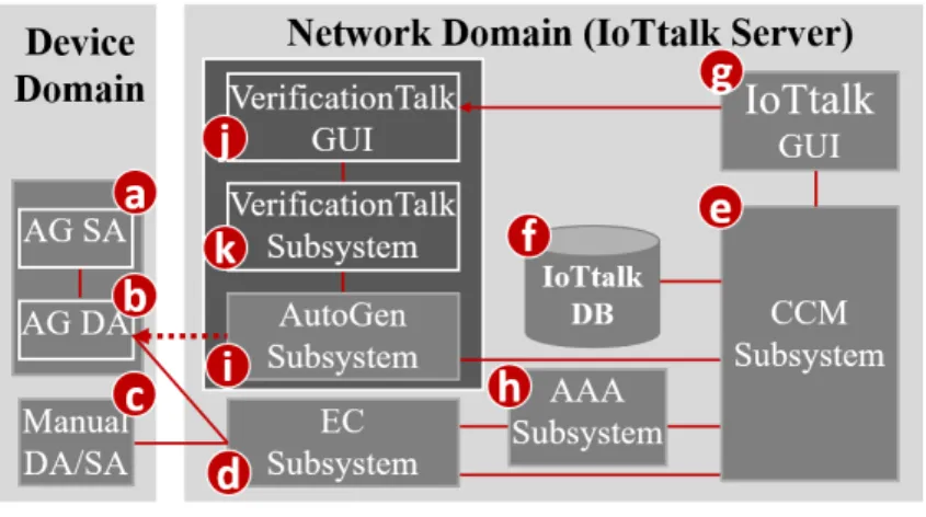
As an IoT application development platform, IoTtalk is defined in two domains [3]:
device domain and network domain. In the device domain, an IoTtalk device (such as a PM2.5 sensor or a light actuator) consists of two software components:
The Sensor and Actuator Application (SA; Fig. 2.1 (a)) is responsible for implementing the IoT device function such as the PM2.5 algorithm or the light intensity and color circuit software.
The Device Application (DA; Fig. 2.1 (b)) is responsible for communications with the IoTtalk network domain. The communication technique can be wired or wireless (e.g., WiFi, LTE, NB-IoT, LoRA, and so on).
The generation of an IoT device's DA/SA software can be automatic (Fig. 2.1 (a)-(b)) or manual (Fig. 2.1 (c)).
Figure 2.1 The IoTtalk architecture.
In the network domain, an IoTtalk server is responsible for provisioning network
applications (NAs) that manipulate the connections and meaningful interactions among the
7
IoT devices. An IoTtalk application or project (such as smart home, smart city, or smart agriculture) is a set of network applications. The server consists of several subsystems (Fig.
2.1 (d)-(k)). The Execution and Control Subsystem (EC; Fig. 2.1 (d)) is responsible for the control plane (the Control Submodule) and the user plane (the Execution Submodule) of the end-to-end path between the IoTtalk devices and the server. The Creation, Configuration and
Management Subsystem (CCM; Fig. 2.1 (e)) systematically creates and manages the network
applications of IoTtalk devices for the corresponding IoT applications. IoTtalk defines adevice model (DM) for real devices with the same properties. For example, a smartphone
device model may represent various real smartphones such as iPhone, Android smartphones, etc. A device model consists of several device features (DFs). For example, a smartphone's acceleration sensor is an Input Device Feature (IDF) that sends data to the EC. A smartphone's speaker is an Output Device Feature (ODF) that receives instructions from the EC. For the configuration purpose, we further partition a device model into the input and the output parts. The input device model is the set of IDFs (e.g., the acceleration sensor, the gyro sensor, the camera, and the microphone of a smartphone). The output device model is the set of ODFs (e.g., the speaker and the screen of the smartphone). The CCM is responsible for managing the device models and their DFs, and stores such information in the IoTtalkDatabase (IoTtalk DB; Fig. 2.1 (f)). The IoTtalk Graphical User Interface (IoTtalk GUI, Fig.
2.1 (g)) is a friendly web-based user interface that allows a developer to establish the network applications among the IoT devices efficiently. The Authentication, Authorization and
Accounting Subsystem (AAA; Fig. 2.1 (h)) is responsible for administering user
accounts and access to the IoTtalk applications. Figure 2.1 (d)-(h) are core components in a typical IoT platform, where the developer manually creates IoT devices and IoT applications through the IoTtalk GUI. Two major network protocols are used in IoTtalk: Message Queueing Telemetry Transport (MQTT) is for the links (b)-(d), (c)-(d), (d)-(e), and (e)-(g);and HyperText Transfer Protocol Secure (HTTPS) is for the link (e)-(g). The IoTtalk DB interacts with the CCM through the Object Relational Mapping (ORM) protocol [22].
IoTtalk also provides an advanced feature called AutoGen, which can automatically generate the devices and the projects (applications). Also, AutoGen forwards the query to the
8
CCM Subsystem to retrieve the specific information from IoTtalk DB. This novel approach for integrating IoT with VerificationTalk is supplied by the AutoGen Subsystem (Fig. 2.1 (i)) that is considered as a platform to create the "VerificationTalk" Subsystem (Fig. 2.1 (k)). We use the VerificationTalk HTTP Service procedure of AutoGen Subsystem to retrieve the information about the IoTtalk application to be verified, including the details of devices, joins, and connection in this application. The VerificationTalk Subsystem is associated with a web-based GUI (Fig. 2.1 (j)) that allows users to select the verification mechanism they want to use freely.
The VerificationTalk Architecture
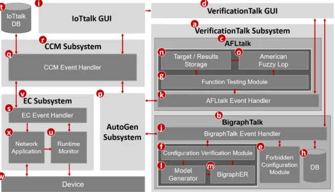
The VerificationTalk Subsystem (Fig. 2.2 (a)) consists of two components: BigraphTalk (Fig. 2.2 (b)) and AFLtalk (Fig. 2.2 (c)), which are associated with a web-based GUI (Fig. 2.2 (d)) that allows users to start up the specific verification mechanism and specify forbidden configurations.
Figure 2.2 The VerificationTalk architecture.
9
To integrate IoTtalk with BigraphTalk and AFLtalk, we add a Forbidden Configuration Module (Fig. 2.2 (e)) and Configuration Verification Module (Fig. 2.2 (f)) into the BigraphTalk [6] and a Function Testing Module (Fig. 2.2 (g)) into the AFLtalk. The Forbidden Configuration Module manages the records of forbidden configurations. The Configuration Verification Module composes the messages for configuration verification requests and interprets the results after verifying the configuration of IoTtalk applications. The Function Testing Module collects the information related to the join function to be tested and decodes the results after verifying join functions of IoTtalk applications.
To specify a forbidden configuration, the VerificationTalk GUI allows a domain expert to define new forbidden configurations by selecting some devices and picking device features associated. Based on VerificationTalk GUI’s inputs, the Forbidden Configuration Module creates, modifies, or deletes the tables related to the forbidden configurations. The tables are stored in the BigraphTalk DB (Fig. 2.2 (h)). After domain experts created or modified a forbidden configuration, all projects automatically apply to such a forbidden configuration.
BigraphTalk guarantees the configuration correctness of IoTtalk applications for users, even if the users have no domain knowledge. We will elaborate on the design and implementation of these tables related to the forbidden configuration in Chapter 3.
In IoTtalk GUI (Fig. 2.2 (i)), if users decide to verify the IoTtalk application, the page will jump from IoTtalk GUI to VerificationTalk GUI, which is represented by the arrow linked from Figure 2.2 (i) to (d). As the page jumps to VerificationTalk GUI, users can select which verification mechanism to be used and verify the IoTtalk applications. Depending on the mechanism chosen by users, the VerificationTalk GUI will send corresponding requests to Configuration Verification Module or Function Testing Module, which are forwarded by BigraphTalk Event Handler (Fig. 2.2 (j)) or AFLtalk Event Handler (Fig. 2.2 (k)), respectively.
As users decide to check the existence of any forbidden configuration, the Configuration Verification Module will pack the configuration information of a specific IoTtalk application to Model Generator (Fig. 2.2 (l)) to construct an instance of the bigraph model corresponding
10
to this IoTtalk application. Then, the BigraphER (Fig. 2.2 (m)) [23], a suite of open-source tools that provide support for specification and verification of bigraphs, will validate the model by matching the model against the forbidden configuration and send the result back to the Configuration Verification Module. The bigraph tools are used in BigraphTalk. We choose an actively maintained open-source tool called BigraphER [23]. An advantage of BigraphER is its provision of a library of matching routines. BigraphER is the only tool supporting features such as parameterized entities essential for our implementation.
While users want to prevent improper operations performed in join functions, the Function Testing Module will store the target function's details into the Target/Results storage (Fig. 2.2 (n)) and initialize the fuzz testing. Once the American Fuzzy Lop (AFL; Fig. 2.2 (o)) [8] completes fuzz testing, it will store the testing results into the Target/Results Storage for Function Testing Module access.
With the VerificationTalk HTTP Service procedures of AutoGen Subsystem (Fig. 2.2 (p)), VerificationTalk can access the information of specific IoTtalk application and display the result of verification on IoTtalk GUI. These procedures will help the VerificationTalk Subsystem to forward the request to the CCM Event Handler (Fig. 2.2 (q)) in the CCM Subsystem (Fig. 2.2 (r)). The CCM Event Handler is responsible for receiving the request from the IoTtalk GUI, EC Event Handler (Fig. 2.2 (s)), and AutoGen Subsystem. It will dispatch the request or execute the corresponding instruction. Any request for querying IoTtalk DB (Fig. 2.2 (t)) must be processed by CCM Event Handler.
When VerificationTalk detects a potential runtime error, it instructs the Runtime Monitor (Fig. 2.2 (u)) in EC Subsystem (Fig. 2.2 (v)) to start up the runtime monitor process. Initially, the data transmitted with the Device (Fig. 2.2 (w)) only need to go through the Network Application (Fig. 2.2 (x)). After the runtime monitor process starts, the data transmitted by Network Application needs to pass through Runtime Monitor to check if it is invalid. The above step can detect anomalies timely before invalid data causes the device to break down.
The details of detecting anomalies are given in Chapter 3.
11
BigraphTalk and Runtime Monitor
This chapter elaborates on BigraphTalk and Runtime Monitor. Section 3.1 briefly describes the concept of bigraphs. Section 3.2 discusses how to verify the configuration of IoTtalk applications. Section 3.3 to Section 3.5 illustrate the implementation of the forbidden configuration management, including the design of graphical user interface, database system, and management procedures. Section 3.6 outlines the extension work from BigraphTalk called Runtime Monitor.
Overview of the Bigraphs
Bigraphs were first introduced by Robin Milner [7] as a universal mathematical model representing the spatial configuration of physical or virtual entities and their interactions [10].
A bigraph is composed of a pair of relations over the same set of nodes: the place graph specifies spatial relationships while the link graph specifies the non-spatial interactions [24].
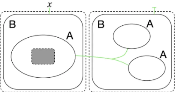
A place graph represents the locality by node placing. A link graph encodes the connectivity by the hyperlinks between entities. Entities, real or virtual, are encoded by nodes, represented as ovals or circles. Nodes are assigned a type, called control, such as labels A and B in Figure 3.1. Controls specify different components of the system.
Locality between entities can be illustrated spatially by nesting one entity within or beside another. Regions, indicated by a dashed rectangle in Figure 3.1, specify the adjacent part of the system. In Figure 3.1, the shaded rectangles are called sites that encode components of the system that have been abstracted away.
Connectivity is defined by the green hyperlinks that connect the entity to the name (such as 𝑥 in Fig. 3.1), the other entities, or not connect to anything. Since all the links are hyperlinks, a single link may connect multiple entities, such as all A entities in Figure 3.1.
Each entity is assigned an arity that determines its number of links. Similar entities always have the same number of links.
12
Figure 3.1 Instance of bigraph.
Configuration Verification
IoTtalk provides a web-based GUI that allows users to configure data interaction among devices [3] [4] [5]. In the IoTtalk GUI, one can create a project window to develop an IoT application. In this window, the Input Device Features (IDFs) of the devices are clustered together on the left side, while the Output Device Features (ODFs) are clustered on the right side. We specify how devices communicate by dragging “Join” lines to connect IDFs and ODFs. Figure 1.1 shows an instance of using IoTtalk GUI to construct an application. There is a single curtain in this application that reads the value sent from the acceleration sensor of a smartphone and uses this value to trigger the curtain motor to move up or down.
When the values sent from an IDF reach the Join point, the IoTtalk server computes the new values for ODFs connected to this Join point. Each ODF connected to the same Join point will receive the same value. However, many applications have sets of ODFs that should not receive the same values simultaneously, and they are considered as forbidden
configurations [6]. To be more specific, the application shown in Figure 3.2 should be
forbidden as it is unreasonable to turn on the heater and the cooler simultaneously in the same room.Figure 3.2 An instance of forbidden configuration involving multiple devices.
13
The forbidden configurations can be statically detected before execution as they occur based on the linking between devices that should never have any connection. Also, the multi-path situation (see Figure 3.3) is taken into consideration. Figure 3.3 gives an application equivalent to the one in Figure 1.1 if we use the same join function for Join 1 and Join 2.
Figure 3.3 An instance of potential forbidden configuration.
To prevent connecting the devices that should never be linked, users can request for verifying the configuration of a specific IoTtalk application by selecting the “Verification”
option (Fig. 3.4 (a)) in the IoTtalk GUI. As users switch on the “Verification” toggle on the navigation bar, the page will jump to the Verification Settings page (see Fig. 3.5) of VerificationTalk GUI.
Figure 3.4 Navigation bar of IoTtalk GUI.
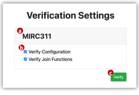
In the Verification Settings Page, we can see which project (Fig. 3.5 (a)) is requesting verification. Below the project’s name, we can see the checkboxes (Fig. 3.5 (b)) for mechanism selection. After the users click the “Verify” button (Fig. 3.5 (c)), VerificationTalk will begin to apply the selected verification mechanism to this IoTtalk application. As the users select the “Verify Configuration” option, the VerificationTalk GUI will request BigraphTalk to check whether there is any forbidden configuration in the IoTtalk application.
Similarly, while the users choose the “Verify Join Functions” option, the VerificationTalk GUI will request AFLtalk to test whether inappropriate operations are performed in the join functions. The details of testing join functions are given in Chapter 4.
14
Figure 3.5 Verification Settings Page.
The following subsections illustrate how BigraphTalk detects forbidden configurations and alerts users if it discovers any forbidden configurations.
Modelling IoTtalk with Bigraphs
The BigraphTalk defines an encoding from the IoTtalk applications to specific instantiations of bigraph models for examining the correctness of the applications. The encoding uses bigraph models to mimic the connection perspective of IoTtalk applications. If any forbidden configurations exist, we can detect them from the corresponding bigraph models. We begin with an informal discussion of the mapping between IoTtalk components and bigraphs entities [6].
Table 3.1 BigraphTalk entities [6].
The entities specified by the encoding are presented in Table 3.1. Each entity has a fixed arity that determines the number of links, a contained-by relation that defines its placement,
15
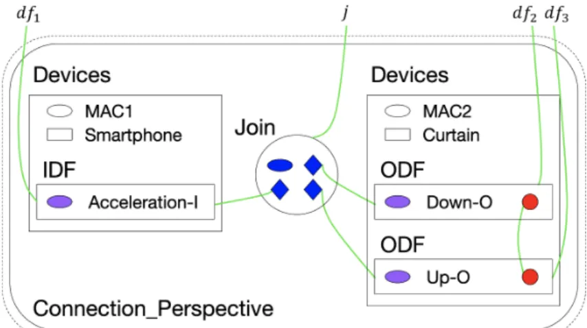
and the entities can link with it [6]. By using these entities and the message from CCM Subsystem (Fig. 2.2 (r)), the Model Generator (Fig. 2.2 (l)) constructs the bigraph instance corresponding to the IoTtalk application. The message from CCM Subsystem includes details of devices, Joins, and connections, and it is in the JSON [25] format. The message format is given in Appendix B. The bigraph models that represent the connection perspective of Figure 1.1 are shown in Figure 3.6.
Figure 3.6 The equivalent bigraph model of IoTtalk application.
Every IoTtalk device corresponds to a Device entity, with the Device_Model entity describing the class of device [6]. A Device always contains a unique Device_Id entity, often its MAC address, to model a specific instance of devices.
A Device contains a set of IDFs or/and ODFs, and each device feature is assigned an identifier called DF_Id entity. This identifier must be unique within a single device. ODFs that must not share an input contain an additional entity called Ind (the red circles in Fig. 3.6) for detecting forbidden configurations [6]. Forbidden configurations are then described by connecting Ind entities for each ODF in the same forbidden configuration together. As bigraphs support hyperlinks between entities, connecting Ind entities, instead of directly linking the ODF entities, allows connections between any number of ODFs [6].
Join entities represent the Joins in IoTtalk applications, and each of them stores a unique Join_Id entity and connections to device features [6]. For the same purpose as Ind entities, the use of Join_pt entities allows an IDF/ODF entity to be connected to any number of
16
Joins [6].
Detecting Forbidden Configurations
As two or more output device features that should not receive the same values simultaneously connect to the same input device feature, the forbidden configurations will occur. A forbidden configuration can occur through either a single path (see Fig. 1.1) or a multi-path (see Fig. 3.3). As the output of a Join can vary by applying different join functions, different ODFs connect to a single input through multiple Joins is not necessarily an error.
However, it has the potential to become the forbidden configuration depending on the join functions.
The bigraph models shown in Figures 3.7 and 3.8 are predicates [26] representing forbidden configurations. In Figure 3.7, the predicate match any instance where two ODFs both connect to a single Join point. This predicate matches regardless of the IDF connected to them. The predicate in Figure 3.8 handles multiple paths from a single IDF to two ODFs. This predicate is similar to the predicate of a single Join in Figure 3.7, but now it relies on checking whether the same IDF connects through two distinct Joins to two ODFs. To represent forbidden configuration predicates with more ODFs, BigraphTalk extends the ideas shown in Figures 3.7 and 3.8 to construct bigraph models with more entities corresponding to the ODFs.
Figure 3.7 Forbidden configuration predicate.
Figure 3.8 Potential forbidden configuration predicate.
17
BigraphTalk uses the matching engine of BigraphER (Fig. 2.2 (m)) [23] to check the correctness of IoTtalk application configuration. This matching engine will discover if a predicate exists within the bigraph model generated by Model Generator.
Feedback from Verification Result
To assist debugging IoTtalk applications, BigraphTalk extracts the identifiers of all devices, device features, and Joins involved in errors during the verification process. After that, BigraphTalk returns such information, including Device_Id, DF_Id, and Join_Id, to CCM Subsystem in the JSON format. The message format returned to CCM Subsystem is given in Appendix C. Then, the CCM Subsystem pushes the information to the IoTtalk GUI (Fig. 2.2 (i)) for display.
The IoTtalk GUI reports invalid configurations to the users as follows. If the verification results indicate the existence of forbidden configurations, the erroneous device features and Joins are colored in red (see Fig. 3.9). IoTtalk GUI warns the users of potential errors by coloring the corresponding device features and Joins yellow (see Fig. 3.10).
Figure 3.9 Forbidden configuration highlighted in red.
Figure 3.10 Potential forbidden configuration highlighted in yellow.
Forbidden Configuration Management Page
VerificationTalk GUI provides a Forbidden Configuration Management page (see Fig.
3.11) that allows domain experts to manage the forbidden configurations. In this section, we will describe how domain experts create, modify and delete the forbidden configurations.
18
Figure 3.11 Forbidden Configuration Management Page.
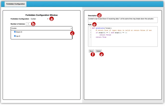
To create new forbidden configurations or modify existing forbidden configurations, the domain expert clicks the selector in the Forbidden Configuration field (Fig. 3.11 (a)) and performs the following actions. To create a new forbidden configuration, he/she choose “add new configuration” (Fig. 3.12 (a)) to enter the new configuration page. To modify an existing configuration, he/she choose its name (Fig. 3.12 (b)) from the existing configuration list to enter the existing configuration page.
Figure 3.12 Create or modify the forbidden configuration.
On the Forbidden Configuration Management page, the Number parameter of the devices field (Fig. 3.11 (b)) specifies the number of devices included in this configuration, and the window (Fig. 3.11 (c)) below devices field allows the selection of the device model
19
and device features involved in each device model. If a user selects three device features in a single device, it means that all the three device features within such device connect to the same input will be detected as an error. As illustrated in Figure 1.1, a curtain cannot move up and down simultaneously. If Up-O and Down-O of the Curtain device receive data 1 at the same time, it may break down the actuator. In this context, we regard the device features Up-O and Down-O within the same device model Curtain as a forbidden configuration if they are connecting to the same input. The Description field (Fig. 3.11 (d)) defines the error message returned to the users after this forbidden configuration is detected. The Rule field (Fig. 3.11 (e)) is a code editor that allows the users to write a rule function named “predicate”
for Runtime Monitor (Fig. 2.2 (u)) to determine whether the transmitted data is valid. The design and implementation of Runtime Monitor will be elaborated in Section 3.6.
After the the fields mentioned above have been set up, the domain expert clicks the
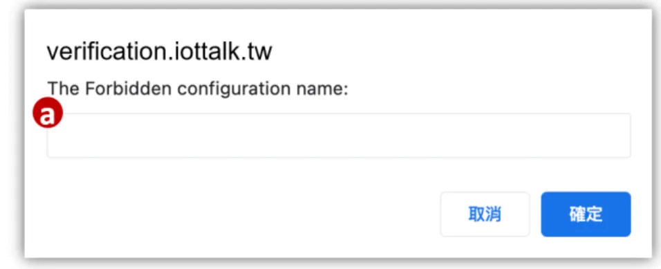
“Save” button (Fig. 3.11 (f)). Then, the page will pop up a window (see Fig. 3.13) for naming this configuration (Fig. 3.13 (a)) and sending the request to Forbidden Configuration Module (Fig. 2.2 (e)) to create or update the forbidden configuration record in BigraphTalk DB (Fig.
2.2 (h)). If users want to delete the specific configuration, they can click the “Delete” button (Fig. 3.11 (g)) to remove the forbidden configuration record from BigraphTalk DB.
Figure 3.13 Name the forbidden configuration.
The Database System of BigraphTalk
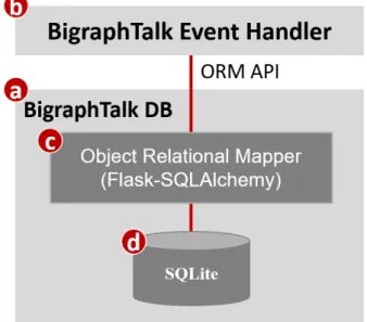
This section describes how information is stored and accessed in the BigraphTalk DB (Fig. 2.2 (h) and Fig. 3.14 (a)). The BigraphTalk Event Handler (Fig. 2.2 (j) and Fig. 3.14 (b))
20
accepts and dispatches HTTP requests through Flask [27], a micro web development framework for Python. It interacts with the BigraphTalk DB for forbidden configuration information retrieval. The BigraphTalk Event Handler accesses the BigraphTalk DB through the Object Relational Mapper (ORM; Fig. 3.14 (c)) [22]. The ORM allows the BigraphTalk Event Handler to connect to different types of databases and convert the data formats between incompatible object-oriented systems.
Figure 3.14 The Database system of BigraphTalk.
In BigraphTalk, we use Flask-SQLAlchemy [28], an extension for Flask, to integrate the BigraphTalk Event Handler with a widely used Python ORM toolkit SQLAlchemy [29] with two advantages. First, Flask-SQLAlchemy handles the database engine [30], connection, and session configuration [31]. Second, it provides a declarative base class [32] that makes querying easier than using SQLAlchemy directly. Therefore, the BigraphTalk Event Handler does not need to know which type of database is accessed. To support a new type of database in the BigraphTalk DB, it only needs to update the codes in the ORM without affecting the BigraphTalk Event Handler. BigraphTalk uses SQLite (Fig. 3.14 (d)) to implement the database because it is easy to set up with low resource consumption [33]. Through ORM, the BigraphTalk also supports other types of databases, such as MySQL or PostgreSQL.
The BigraphTalk DB maintains the information related to forbidden configurations,
21
containing two tables: ForbiddenConfiguration and ForbiddenFeature.
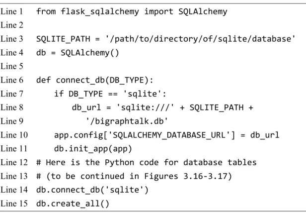
The Python code for BigraphTalk DB initialization is listed in Figures 3.15-3.17. It includes the database configuration and definitions of the tables.
Line 1 from flask_sqlalchemy import SQLAlchemy Line 2
Line 3 SQLITE_PATH = '/path/to/directory/of/sqlite/database' Line 4 db = SQLAlchemy()
Line 5
Line 6 def connect_db(DB_TYPE):
Line 7 if DB_TYPE == 'sqlite':
Line 8 db_url = 'sqlite:///' + SQLITE_PATH + Line 9 '/bigraphtalk.db'
Line 10 app.config['SQLALCHEMY_DATABASE_URL'] = db_url Line 11 db.init_app(app)
Line 12 # Here is the Python code for database tables Line 13 # (to be continued in Figures 3.16-3.17)
Line 14 db.connect_db('sqlite') Line 15 db.create_all()
Figure 3.15 The Python code for the BigraphTalk Event Handler to initialize the BigraphTalk DB.
In Figure 3.15, Line 1 imports the SQLAlchemy class [34] from Flask-SQLAlchemy for the BigraphTalk Event Handler to access the BigraphTalk DB. Line 3 defines the settings of SQLite. For SQLite, the database is stored in the directory located at SQLITE_PATH (Line 3).
Line 4 defines a global variable db as an object of the SQLAlchemy class. This object contains a preconfigured scoped session, an engine instance that is the home base for the actual database, and so on. The function connect_db(), defined in Lines 6-13, configures and connects to BiigraphTalk DB. Lines 7-9 declare a variable db_url to record the entry point of the BigraphTalk DB. Line 10 stores the entry point of the BigraphTalk DB in the global variable app (which is a Flask instance for the BigraphTalk Event Handler to register functions to handle HTTP requests). Line 11 loads the entry point of BigraphTalk DB from the variable app, and it creates the database engine and initializes the connection to BigraphTalk DB. Lines 12-13 define the tables related to forbidden configurations. Line 14
22
invokes the connect_db() function to connect to the BigraphTalk DB. The argument sqlite represents that the implementation of the database is based on SQLite. Line 15 invokes the
create_all() method predefined in the SQLAlchemy class to generate all tables defined in
Lines 12-13.The following subsections describe the tables related to forbidden configurations. These tables store the names and descriptions of the forbidden configurations and the rules for detecting invalid data.
The ForbiddenConfiguration Table
The ForbiddenConfiguration Table maintains the forbidden configuration attributes.
Table 3.2 illustrates the record for Curtain forbidden configuration (as displayed in Figure 3.11) in the ForbiddenConfiguration Table. The description column stores the error message returned to the users after this forbidden configuration is detected. The rule column defines a rule function named “predicate,” which is for Runtime Monitor (Fig. 2.2 (u)) to determine whether the transmitted data is invalid.
fc_id fc_name description rule
1 Curtain Curtain’s Up-O and Down-O receiving data 1 …
def predicate(*args):
… Table 3.2 The ForbiddenConfiguration Table.
The Python class for the ForbiddenConfiguration Table is listed in Figure 3.16. Lines 3-12 define the columns in the ForbiddenConfiguration Table. Lines 9-12 create a one-to-many relationship that associates one record in the ForbiddenConfiguration Table with many records in the ForbiddenFeature Table (to be described in Section 3.4.2).
Line 1 class ForbiddenConfiguration(base):
Line 2 __tablename__ = 'ForbiddenConfiguration' Line 3 fc_id = Column(
Line 4 Integer, primary_key=True, nullable=False Line 5 )
Line 6 fc_name = Column(String(100), nullable=False)
23
Line 7 description = Column(Text, nullable=True, default='') Line 8 rule = Column(Text, nullable=False)
Line 9 forbiddenfeature = relationship(
Line 10 'ForbiddenFeature', cascade="all, delete", Line 11 backref='forbiddenconfiguration'
Line 12 )
Figure 3.16 The Python class for the ForbiddenConfiguration Table.
The ForbiddenFeature Table
The ForbiddenFeature Table stores the information of all device features within the same forbidden configuration. Table 3.3 shows the records related to Curtain forbidden configuration (as displayed in Figure 3.11) in the ForbiddenFeature Table. The df_id and
dm_id columns identify the specific device feature within the particular device model. The
df_id and dm_id in the records of Table 3.3 represent the device features Up-O and Down-O within the device model Curtain. The d_idx column indicates whether the device features are in the same device model. The device features with the same d_idx belong to the same device.In Table 3.3, both device features in the Curtain forbidden configuration have the same d_idx since they are in the same device model.
ff_id fc_id dm_id df_id d_idx
1 1 33 127 0
2 1 33 128 0
Table 3.3 The ForbiddenFeature Table.
The Python class for the ForbiddenFeature Table is listed in Figure 3.17. Lines 3-10 define the columns in the ForbiddenFeature Table. In Line 6, the ForeignKey class specifies
fc_id as a foreign key column of the ForbiddenFeature Table, which references the fc_id
column of the ForbiddenConfiguration Table.Line 1 class ForbiddenFeature(base):
Line 2 __tablename__ = 'ForbiddenFeature'
Line 3 ff_id = Column(Integer, primary_key=True, nullable=False) Line 4 fc_id = Column(
24
Line 5 Integer, nullable=False,
Line 6 ForeignKey('ForbiddenConfiguration.fc_id') Line 7 )
Line 8 dm_id = Column(Integer, nullable=False) Line 9 df_id = Column(Integer, nullable=False) Line 10 d_idx = Column(Integer, nullable=False)
Figure 3.17 The Python class for the ForbiddenFeature Table.
Forbidden Configuration Management Procedures
This section describes the procedures in the Forbidden Configuration Module for supporting operations related to forbidden configurations. The following subsections illustrate two commonly used management procedures. All the other management procedures and the corresponding rules are listed in Appendix D.
create_forbidden_configuration()
When the domain expert tries to click the “Save” button (Fig. 3.11 (f)) to create a forbidden configuration, the browser will send an HTTP PUT request to the BigraphTalk Event Handler, which will redirect this request to Forbidden Configuration Module. Figure 3.18 shows the HTTP message for creating a Curtain forbidden configuration. Line 1 indicates the PUT method and a resource name “/fc/create”. The content-type specifies that this message body is represented in the JSON format (Line 2). Lines 3-9 are the JSON-format data representing the newly added forbidden configuration information. The value corresponding to the key ff_list represents all forbidden features within the same forbidden configuration. In this context, Lines 4-7 indicate the device features Up-O and Down-O within the same Curtain device.
Line 1 PUT /fc/create HTTP/1.1
Line 2 Content-Type:application/json Line 3 {'fc_name': 'Curtain',
Line 4 'ff_list': [{
Line 5 'dm_id': 1, Line 6 'df_id': [1, 2]
25
Line 7 }],
Line 8 'description': "Curtain's Up-O and Down-O receiving ...", Line 9 'rule': "def predicate(*args): ... "}
Figure 3.18 The HTTP message to create the Curtain forbidden configuration.
Upon reception of this message, the Forbidden Configuration Module invokes
create_forbidden_configuration(). The invoked procedure checks whether the name of the
newly added forbidden configuration exists. If this name has not yet been used, this procedure will create a new forbidden configuration record. The create_forbidden_configuration() procedure will insert such records into the BigraphTalk DB (Fig. 2.2 (h)).The Python code for the procedure create_forbidden_configuration() is shown in Figure 3.19. Line 1 imports the Requests module [35], an elegant and simple HTTP library for Python, built for human beings. Line 2 defines a global variable AutoGen_url to record the entry point of the AutoGen Subsystem. Lines 6-9 retrieve the attributes of the newly added forbidden configuration from the HTTP message. Lines 10-14 check whether the name of the just added forbidden configuration exists. If this name has not yet been defined, Lines 17-20 will insert a new forbidden configuration record into the BigraphTalk DB. Lines 21-39 insert the forbidden feature records included in this configuration into the BigraphTalk DB. Lines 23-26 invoke requests.post() to send an HTTP POST message to the AutoGen Subsystem to get the information about device features within a specific device model. After the create_forbidden_configuration() finish the actions above, the BigraphTalk Event Handler returns an HTTP status code 200 OK and the identity of just created forbidden configuration to the browser.
Line 1 import requests
Line 2 AutoGen_url = 'http://localhost:8000/autogen/ccm_api' Line 3
Line 4 @app.route('/fc/create', methods=['PUT']) Line 5 def create_forbidden_configuration():
Line 6 fc_name = flask.request.json.get('fc_name') Line 7 ff_list = flask.request.json.get('ff_list') Line 8 rule = flask.request.json.get('rule')
26
Line 9 description = flask.request.json.get('description', '') Line 10 fc_record = ForbiddenConfiguration.query
Line 11 .filter_by(fc_name == fc_name).first() Line 12 if fc_record:
Line 13 raise Exception('Forbidden Configuration ' + Line 14 f'"{fc_name}" already exists.')
Line 15 if not ff_list:
Line 16 raise Exception('Forbidden Features cannot be empty.') Line 17 new_fc = ForbiddenConfiguration(fc_name=fc_name,
Line 18 description=description, rule=rule) Line 19 db_session.add(new_fc)
Line 20 db_session.commit()
Line 21 for index, device_info in enumerate(ff_list):
Line 22 dm_id = device_info['dm_id']
Line 23 df_info_list = requests.post(AutoGen_url, data = { Line 24 'api_name':'devicemodel.get',
Line 25 'payload': json.dumps({'dm_id': dm_id})}) Line 26 .json()['df_list']
Line 27 mf_info_list = []
Line 28 for df_info in df_info_list:
Line 29 if df_info['df_id'] in device_info['df_id']:
Line 30 mf_info_list.append(df_info['df_id']) Line 31 if not (mf_info_list and
Line 32 len(mf_info_list) == len(device_info['df_id'])):
Line 33 raise Exception('(dm_id, df_id) mismatch.') Line 34 for df_id in mf_info_list:
Line 35 new_ff = ForbiddenFeature(
Line 36 fc_id=new_fc.fc_id, dm_id=dm_id, Line 37 df_id=df_id, d_idx=index)
Line 38 db_session.add(new_ff) Line 39 db_session.commit()
Line 40 return jsonify({'fc_id': new_fc.fc_id})
Figure 3.19 The Python code for create_forbidden_configuration().
27
get_forbidden_configuration_info()
As users click the selector in the Forbidden Configuration field (Fig. 3.11 (a)) and select Curtain forbidden configuration to check its details, the browser will send an HTTP GET request. Then, the BigraphTalk Event Handler will redirect this request to the Forbidden Configuration Module. The HTTP message for querying a forbidden configuration is shown as follows:
GET /fc/info/1 HTTP/1.1
where “1” identifies the Curtain forbidden configuration. Upon receiving this message, the BigraphTalk event handler invokes get_forbidden_configuration_info() to get the specific forbidden configuration information. Figure 3.20 lists the Python code for the procedure get_forbidden_configuration_info(). Lines 4-5 use fc_id to obtain the forbidden configuration record and assign it to the variable fc_record. Line 6 checks if fc_record is None. If it is None, it means that this forbidden configuration record does not exist, then Lines 7-8 will use the raise statement to force a specified exception to occur. Lines 9-15 parse the forbidden feature records involved in this forbidden configuration into a list and assign it to the variable ff_list.
Lines 16-19 return the forbidden configuration information represented in the JSON format to the browser.
Line 1 @app.route('/fc/info', methods=['GET']) Line 2 def get_forbidden_configuration_info():
Line 3 fc_id = flask.request.args.get('fc_id') Line 4 fc_record = ForbiddenConfiguration.query Line 5 .filter_by(fc_id == fc_id).first() Line 6 if not fc_record:
Line 7 raise Exception('Forbidden Configuration ' + Line 8 f'"{fc_id}" not exists.')
Line 9 ff_record_list = ForbiddenFeature.query Line 10 .filter_by(fc_id == fc_id)
Line 11 .order_by(d_idx).all() Line 12 ff_list = []
Line 13 for ff_record in ff_record_list:
28
Line 14 ff_list.append((ff_record.d_idx, Line 15 ff_record.dm_id, ff_record.df_id)) Line 16 return jsonify({'fc_id': fc_record.fc_id, Line 17 'fc_name': fc_record.fc_name,
Line 18 'description': fc_record.description,
Line 19 'ff_list': ff_list, 'rule': fc_record.rule}) Figure 3.20 The Python code for get_forbidden_configuration_info().
Design and Implementation of Runtime Monitor
In this section, we first describe why we need the runtime monitor. Then we elaborate on the runtime monitor design and the implementation. Finally, we evaluate the performance of our implementation.
After the BigraphTalk verified the connections of the IoT devices, the IoTtalk GUI will indicate the errors if any. Data transmission is forbidden if the corresponding Joins and ODFs are marked in red (see Fig. 3.21 (a)). The blocks marked in yellow represent potential errors (see Fig. 3.21 (b)), namely, runtime errors that may occur.
Figure 3.21 IoTtalk GUI displaying the erroneous configurations in IoTtalk application.
Some runtime errors may happen. For instance, a curtain cannot move up and down simultaneously. Otherwise, the actuator of the curtain might break down. To prevent such circumstances, we need a runtime data monitor to intercept invalid data. Figure 3.22 illustrates how Runtime Monitor works. Before the data reaches the output device, we check if it is valid. Then, forward the data if valid or discard it if invalid.
29
Figure 3.22 Detect a potential error through Runtime Monitor.
If BigraphTalk finds any potential error, the Runtime Monitor (Fig. 2.2 (u)) in EC Subsystem (Fig. 2.2 (v)) will assign a runtime monitor process and a rule function to each instance. We use the Process class from the multiprocessing module [36] to construct the runtime monitor process. Initially, the data transmitted from input devices to output devices only need to go through Joins. After the runtime monitor process starts, the data transmitted by Joins related to potential errors need to be examined by the runtime monitor process.
The runtime monitor process executes its rule function to examine the data. The rule function will return True to indicate the transmitted data is valid or False if not. The assigned rule function for Curtain forbidden configuration is shown in Figure 3.23.
Line 1 def predicate(*args):
Line 2 # return True if input data is valid or return False if not Line 3 if args[0] == 1 and args[1] == 1:
Line 4 return False Line 5 return True
Figure 3.23 The Python code of rule function.
In Figure 3.23, Line 1 defines a rule function named “predicate”. The variable args is a list of arguments of the rule function. These arguments are the data transmitted on the monitored Joins. Line 3 checks whether the transmitted data violate the rule. Since a curtain cannot move up and down simultaneously, the Up-O and Down-O contained in a single device Curtain must not receive data “1” at the same time. Lines 3-4 reject such data to protect the curtain motor.
In Figure 3.24, the ODFs Up-O and Down-O of Curtain only receive data 0. Even though IDF sends out data “1” (see Fig. 3.24 (a)), they will not receive data “1” (see Fig. 3.24 (b)) because the runtime monitor process intercepts it.
30
Figure 3.24 Runtime Monitor intercepts invalid data.
As the runtime monitor process intercepts the abnormal data, it will remind users with an alert icon (Fig. 3.24 (c)) on the navigation bar of IoTtalk GUI. As the users click this icon, GUI will pop up a dialog window (see Fig. 3.25), which contains the error message. The error message is related to the invalid data intercepted by the runtime monitor process. In this dialog window, the users can see the value of invalid data (Fig. 3.25 (a)) and the segment where it occurred (Fig. 3.25 (b)).
Figure 3.25 Dialog window displaying the error message related to invalid data.
31
Logging Service
As the runtime monitor process intercepts abnormal data, it also records this invalid data and its information into a specific log file. These logs are useful for future research purposes.
Figure 3.26 shows an instance of the log format.
Line 1 {'rm_id': 1, Line 2 'info': [{
Line 3 'na_id': 1, Line 4 'dfo_id': 1,
Line 5 'join_output': [1],
Line 6 'timestamp': '2021-03-15 11:23:50.000000', Line 7 }, {
Line 8 'na_id': 2, Line 9 'dfo_id': 2,
Line 10 'join_output': [1],
Line 11 'timestamp': '2021-03-15 11:23:50.000030', Line 12 }]}
Figure 3.26 Instance of logging service record.
In Figure 3.26, Line 1 specifies the identifier of the runtime monitor process. The value corresponding to the key info represents the intercepted data and related information. The information includes which segment detects the data and when the runtime monitor intercepts the data. In this context, Lines 2-12 indicate the invalid data that should have been passed to the device features Up-O and Down-O.
Performance of Runtime Monitor
In this subsection, we evaluate the performance of Runtime Monitor through two experiments. These two experiments are related to the transmission time of data transfer between devices. All experiments are conducted on the IoTtalk server and the devices connected to the server through 4G LTE. The IoTtalk is equipped with an Intel Core i7 4770 (3.4 GHz), 16 GB RAM, and Ubuntu 16.04 installed.
To show the impact of the Runtime Monitor, we compared the distribution of the delay
32
from the input device to the output device when the Runtime Monitor is on (see Fig. 3.22) and when it is off (see Fig. 3.10). When the Runtime Monitor is off, the delay from the input device to the output device only needs to consider the transmission time from the input device to the IoTtalk server, the processing time of Joins, and the transmission time from the IoTtalk server to the output device. When the Runtime Monitor is on, the delay from the input device to the output device requires additional consideration of the processing time of the runtime monitor process. We measure 1000 delays from the input device to the output device for analysis when the Runtime Monitor is on and when it is off, respectively. When the Runtime Monitor is off, the average delay is 54.62 milliseconds, and the standard deviation is 13.03 milliseconds. When the Runtime Monitor is on, the average delay is 65.42 milliseconds, and the standard deviation is 7.65 milliseconds. Turning on the Runtime Monitor will make the average delay longer but the standard deviation smaller. The Runtime Monitor increases less overhead when the original delay is longer. In Figure 3.27, we can see that compared to turning off Runtime Monitor, the distribution of delay will be denser when turning on Runtime Monitor. This phenomenon is mainly caused by the fact that Runtime Monitor accumulates the data to be transmitted through the monitored Joins and centrally determines whether it is abnormal. According to Figure 3.27, we can guarantee that the Runtime Monitor performs well because it only causes an insignificant increase in delay. Compared with turning off Runtime Monitor, the average delay only increases 10.79 milliseconds when turning on Runtime Monitor.
Figure 3.27 Distribution of delay when the Runtime Monitor is on/off.