國
立
交
通
大
學
資訊科學與工程研究所
碩
士
論
文
網路控制與管理 - 應用於交通大學無線網
路環境
Networking Control and Management in NCTU Wireless
Environment
研 究 生:沈嘉崑
網路控制與管理 - 應用於交通大學無線網路環境
Networking Control and Management in NCTU Wireless Environment
研 究 生:沈嘉崑 Student:Chia-Kun Shen
指導教授:謝筱齡 Advisor:Sheau-Ling Hsieh
蔡文能 Wen-Nung Tsai
國 立 交 通 大 學
資 訊 科 學 與 工 程 研 究 所
碩 士 論 文
A ThesisSubmitted to Institute of Computer Science and Engineering College of Computer Science
National Chiao Tung University in partial Fulfillment of the Requirements
for the Degree of Master
in
Computer Science July 2006
Hsinchu, Taiwan, Republic of China
網路控制與管理 — 應用於交通大學無線
網路環境
學生: 沈嘉崑
指導教授:
謝筱齡
蔡文能
國立交通大學資訊工程學
系 (研究所) 碩士班
摘要
在交通大學的校園中, 已經設置了很多無線網路基地台。 它們大多數
都被
某個單位所設置。 並且, 交通大學目前更進一步進行建置“無線辦公
室及無
線教育環境”的研究。 換句話說, 交大校園內已經積極的邁向無線
網路化。
當這個無線網路的環境擴大時, 無線網路的涵蓋範圍也隨著無線基
地台的增設而增加。 在這個無線網路環境下的無線網路基地台的管理也
慢慢的變得愈來愈困難。 當這些基地台中的某一個基地台發生了故障時,
管理者也許沒有辦法立刻警覺到這個問題的發生。 此時, 一個能夠幫助
管理者偵測無線基地台的管理系統也就變得十分重要。
在這篇論文中, 我們將會介紹目前交通大學的無線網路架構。 根據這
個架構, 我們設計一個符合交通大學校園的監測系統。 這個系統不但能
指明基地台的位置, 確認這個設備的狀態, 並且能夠在無線基地台故障
時, 發出通報給系統管理員。 我們並且做了一些效能分析來闡述這個系
統的可用性。
關鍵字:SNMP,JMX,XMPP
Networking Control and Management in NCTU
Wireless Environment
Student: Shen, Chia-Kun
Advisors:
Dr. Sheau-Ling Hsieh
Dr. Wen-Nung Tsai
Department(Institute) of Computer Science and Engineering
National Chiao Tung University
Abstract
There is a numerous number of wireless Access Points (APs) installed on NCTU campus. Many of them are established by individual groups for re-search purposes. In addition, NCTU has been under developing with further investigation to construct “free of cord offices and education environment”. In other words, the campus has been progressively moving towards wireless. As the service expands, the coverage of wireless hotspot increases due to more and more access points set up. The management of access points become difficult. One access point in between so many access points may suddenly fails, and the administrator can not be aware of this situation im-mediately. A control system that helps administrators to monitor the access points become essential.
In this thesis, we will introduce the wireless network infrastructure in NCTU campus. According the structure of wireless network in NCTU, we designed a monitoring system for NCTU campus. The system not only can indicate, verify the latest status of the devices but can notify system ad-ministrators when access point fails. We also perform some performance evaluations to demonstrate the usability of this system.
誌謝
這篇論文完成的過程中, 經過了很多波折。 追求完美的我, 希望把這
篇論文做得很好。 於是, 從一開始所採用的架構, 到最後截稿前所採用的
架構, 歷經了多次改版。 到現在, 總算有比較讓我滿意的成果了。
首先我要感謝我的指導教授謝筱齡老師和蔡文能老師, 他們不但提供
了
許多物質上的幫助, 讓我沒有經濟上的壓力; 另外也不斷的訓練我對
於“獨立思考”能力的培養。 這篇論文得以完成, 他們是我最主要感謝的
人。
這裡也同時感謝很多幫助我完成這篇論文的人, 包括嘉銘學姊、宗易學
長, 他們提供了我許多關於學校無線網路架構的資料; 也感謝在實驗室
裡每天從早到晚一起生活、 打拚的實驗室成員—宏文、名榤、東泰、葉薰,
在這段時間給我許多鼓勵。
我也感
謝我的家人能忍受我好像失蹤一樣的幾個月沒回家, 也感謝女
朋友琬
瑜忍受我的固執, 且在最後這段時間陪我練習口試。
謝謝你們!
Contents
1 Introduction 1
2 Background 3
2.1 Wireless Protocol . . . 3
2.2 Wireless Gateway . . . 4
2.3 WLAN in NCTU Campus . . . 4
2.3.1 Main Structure . . . 4
2.3.2 Other Cases . . . 5
2.3.3 Summary . . . 8
3 Technologies 9 3.1 Simple Network Management Protocol . . . 9
3.1.1 Basic Component . . . 9
3.1.2 Management Information Base . . . 10
3.1.3 SNMP Operations . . . 11
3.2 Java Management Extensions . . . 12
3.2.1 Introduction . . . 12
3.2.2 Architecture . . . 14
3.3 Instant Messaging and Presence Technologies . . . 16
3.3.1 Brief History . . . 16
3.3.2 General Model of Presence and Instant Messaging . . . 16
3.3.3 Extensible Messaging and Presence Protocol . . . 18
4 Design 22 4.1 Requirement . . . 22 4.2 System Structure . . . 23 4.2.1 Web Server . . . 23 4.2.2 Jabber Server . . . 25 4.2.3 Agent . . . 25 4.2.4 Database . . . 26 4.2.5 Summary . . . 26
4.3 Program Structure . . . 27 4.3.1 Agent . . . 27 4.3.2 Web Structure . . . 27 4.3.3 Jabber . . . 29 4.4 Summary . . . 30 5 Implementation 32 5.1 Agent . . . 32 5.1.1 MBean . . . 32 5.1.2 MBean Server . . . 35 5.2 Web . . . 38 5.3 Database . . . 44 5.4 Analysis . . . 46 5.4.1 Tool . . . 47 5.4.2 Analysis Result . . . 48
List of Figures
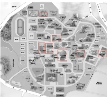
2.1 Hotspot distribution in Chaio-Tung University . . . 5
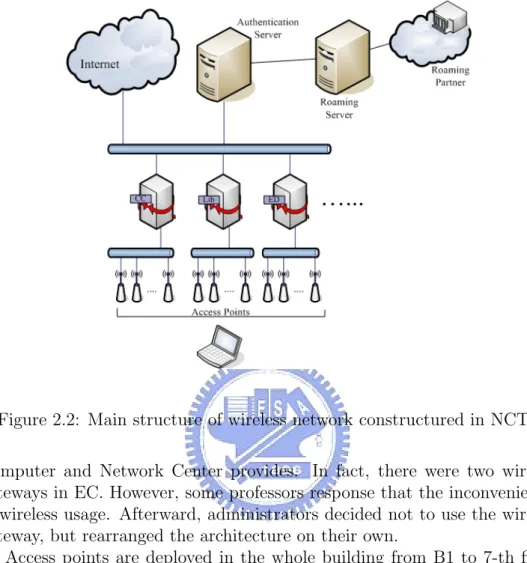
2.2 Main structure of wireless network constructured in NCTU . . 6
2.3 The structure of wireless network in EC . . . 7
2.4 The structure of wireless network at 7th floor in EC . . . 7
3.1 The structure of SNMP . . . 10
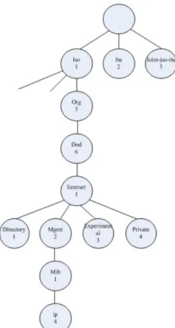
3.2 SNMP MIB hierarchy . . . 11
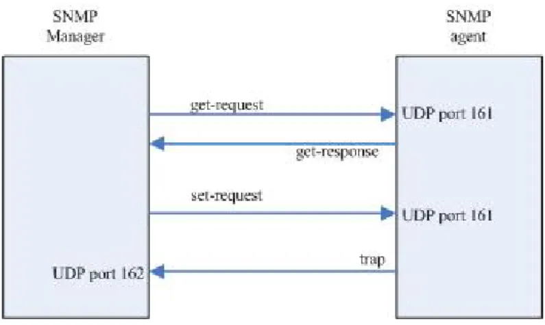
3.3 SNMP operations . . . 12
3.4 The scenario before JMX implemented . . . 13
3.5 The scenario after JMX implemented . . . 14
3.6 The architecture of JMX . . . 15
3.7 The general model of an IM service . . . 17
3.8 The message flow of an IM service. (a). Presence service (b). Instant messaging service . . . 19
3.9 A scenario of the Jabber service . . . 20
4.1 The basic architecture of wireless monitoring system . . . 24
4.2 The program structure of wireless monitoring system . . . 28
4.3 MVC design pattern . . . 29
4.4 The structure of the web based management console in the wireless monitoring system . . . 30
4.5 The scenario when deploying the wireless monitoring system into NCTU . . . 31
5.1 Basic components of joesnmp API . . . 34
5.2 Actions of the JabberClient after booting the agent . . . 36
5.3 Initialization of AccessPoint MBeans . . . 37
5.4 Agent class diagram . . . 39
5.5 Labels of access points on the plan. White lebel indicates teh normal access point red label indicates the abnormal access point. . . 41
5.7 Sequence of deleting access points . . . 44
5.8 Architecture of JConsole . . . 47
5.9 Analysis: Class loading . . . 50
5.10 Analysis: Heap usage . . . 50
5.11 Analysis: Thread amounts . . . 51 5.12 Non-heap usage in the agent after a series of operations on it . 52 5.13 Number of threads in the agent after a series of operations on it 53
List of Tables
2.1 Comparisons of IEEE 802.11 standard . . . 3
5.1 Database schema of agent . . . 45
5.2 Database schema of apinfo . . . 46
Chapter 1
Introduction
In the recent years, wireless network is quite a hot topic. Companies, gov-ernment departments, or universities are engaged in the wireless research, which lead to not only the evolution of wireless technologies but also the cheap wireless equipments. Many public places such as cafe, hotel or subway stations, provide the wireless service for customers.
In Taiwan, “Challenge 2008 —Council for Economic Planning and De-velopment” was brought up by Executive Yuan to construct an “e-society” in Taiwan[3]. Roaming Authentication Exchanging Center[2] was set up by Industrial Development Bureau, Ministry of Economic Affairs. Users can use wireless resources in the hotspot provided by wireless service providers joined in the Roaming Authentication Exchanging Center with a single ac-count. Roaming Authentication Exchanging Center also provides roaming between educational institutions. Faculties and students can use wireless resources in other schools with the account provided by their own school. Roaming between educational institutions integrates wireless environments constructed by each educational institution and shares the resources and in-formation with each other. National Chiao-Tung University (NCTU) is also a member of this roaming network now. NCTU has been under developing with further investigation to construct “free of cord offices and education environmen”. In other words, the campus has been progressively moving towards wireless.
As the service expands, the coverage of wireless hotspot increases due to more and more access points set up. We can foresee a problem: How do we manage the increasing access points? Can wireless administrators found the failure when one or more than one access points fails due to unpredictable reasons? For service providers, they charge the wireless service according to the time elapsed customer accessed the internet. The cost could be very huge before the recovery of the access points, including the time service providers
can provide in these areas and satisfaction of customers.
The objective of this thesis is to propose a wireless managing and moni-toring system. Wireless administrators can get the status of wireless points and get acknowledged by a warning mechanism from the monitoring system. Administrators can be acknowledged immediately when the access point fails. We choose NCTU as our target to design this system. By surveying the wire-less architecture in the university and develop the monitoring system, we are sure that we can build a monitoring system in a larger area.
In chapter 2, we introduce the wireless environment of our design target – NCTU. In chapter 3, we introduce several technologies relevant to network management, which is inclusive of Grid Monitoring Architecture, Simple Net-work Management Protocol (SNMP), Java Management Extension (JMX); We also introduce an instant messaging protocol: Extensible Messaging and Presence Protocol (XMPP). In chapter 4, we start to describe the frame-work we design, including each component in the architecture. In chapter 5, we describe the detail of our implementation. In chapter6, we will make a conclusion and discuss the future work of this system.
Chapter 2
Background
2.1
Wireless Protocol
IEEE 802.11 is so far the most popular wireless internet protocols. It is defined by the Institute of Electrical and Electronic Engineers. IEEE defined IEEE 802.11a, 802.11b and 802.11g based on the difference of frequency band and transmission rates. Table 2.1 shows the three standards.
The transmission rate of IEEE 802.11b is the lowest. However, it oper-ates on the 2.4G frequency band. 2.4-GHz frequency band is reserved for industrial, scientific and medical usage, which is license-free; in addition, IEEE 802.11b is a wireless standard proposed earlier than others, so most institute deploy IEEE 802.11b in their wireless network. Compared with IEEE 802.11b, IEEE 802.11a operate on 5-GHz frequency band, which is not unlicensed band in Taiwan. IEEE 802.11g is proposed recent years. It not only has the same transmission rate as IEEE 802.11a, but also operates on 2.4-GHz band, so will gradually substitute IEEE 802.11b in the campus.
802.11b 802.11a 802.11g Max transmission rate (Mbps) 11 54 54 Frequency band (GHz) 2.4 5 2.4 Transmission range 300 feet 180 feet 300 feet
2.2
Wireless Gateway
Wireless gateway is an internet equipment which routes packets from wireless network to another network[18]. Typically, wireless gateway used to receive connection request from wireless network and routes to a wired network.
Public WLAN (PWLAN) is a WLAN which is deployed in the public environment. Clients can use the internet resources only after authenticated. To construct a PWLAN, the wireless gateway must provide some functions:
• Encryption and authentication module • Web and DHCPD module
• Routing and bandwidth-shaping module
These modules can be provided by a single machine or separate into dif-ferent machines. When a user wants to connect to internet in the PLAN network, after associate with access point, the client would make a DHCP request. The gateway would give the client a lease. At this point, the client has not been authenticated, so the gateway only permits the clients to com-municate with the gateway. When client starts a browser to connect a web site, the HTTP request will be redirected to the captive portal [18] web page. The captive portal is a web page, which is often used in the PWLAN. Gate-way use MAC filtering captures all HTTP requests from the unauthenticated user’s machine and redirect to the captive portal. After authentication com-pleted, the client sets a tunnel to the gateway. Gateway allows only traffic through the tunnel. Routing module shares a separate tunnel with each au-thenticated client, all traffic that are not through tunnel will be redirected to the captive portal which means that they can not connect to the internet. Authenticated users access the internet through their tunnels.
Routing module also provides bandwidth-shaping. When a service provider wants to provide paid user a higher bandwidth and unpaid user a limited bandwidth, routing module can achieve this function.
2.3
WLAN in NCTU Campus
2.3.1
Main Structure
In NCTU, wireless points has been deployed in the following areas: Engineer-ing BuildEngineer-ing 3(EC), EngineerEngineer-ing BuildEngineer-ing 4 (ED), Library and Information Center (Lib), Microelectronics and Information Systems Research Building
Figure 2.1: Hotspot distribution in Chaio-Tung University
(EIC), Student Dormitory 9 (Dorm9), Information Building (CC) and Stu-dent Activity Center (SAC). The following graph shows the coverage area:
The main structure of wireless LAN constructed by Computer and Net-work Center is shown in Figure 2.2.
A wireless gateway is deployed in each hotspot on the campus. All access points in the hotspot connect to its wireless gateway. As described in pre-vious section, when a wireless user wants to access the internet, the request would be redirected to the captive portal page on the authentication server by the wireless gateway. After authenticated, the user can successfully access the internet. The accounts students used in the campus are email address provided by the computer center or by each department. NCTU has joined the roaming service that Roaming Authentication Exchanging Center[2] pro-vides. For a student from other university who wants to use wireless network in NCTU, he can authenticate with his email account provided by his school or university, if his school or university also joined the roaming service
2.3.2
Other Cases
There are two hotspots in NCTU that are not use the same architecture as described above: EC and EIC. For some reasons they choose to use their own architecture without Computer and Network Center constructs.
Figure 2.2: Main structure of wireless network constructured in NCTU Computer and Network Center provides. In fact, there were two wireless gateways in EC. However, some professors response that the inconveniences of wireless usage. Afterward, administrators decided not to use the wireless gateway, but rearranged the architecture on their own.
Access points are deployed in the whole building from B1 to 7-th floor, among which the deployment from first floor to sixth floor is shown in Figure 2.3. Each floor is deployed 8 IEEE 802.11b access points, and centered on a switch that forms a start topology. The switch in each floor connects to a DHCP/NAT server. When a user associates to a access point and make a DHCP request, the DHCP server gives him a lease with a public IP address. User can access the internet with this public IP address without any authentication.
The 7-th floor of EC was built in recent years, so wireless network was built with newer IEEE 802.11g access points and authenticated by a Radius server. As shown in Figure 2.4:
The wireless network is also adopted the structure of Computer and Net-work provides. However, the first floor of EIC is a conference hall, which can be rented by organizations outside the university. As a result, users who come to the conference hall are not necessarily faculties or students in NCTU.
Figure 2.3: The structure of wireless network in EC
People who attend the conference and want to use the wireless network often do not know how to authenticate. They are confused with the authentication and administrators have to give them temporary accounts one by one. Dur-ing one conference, administrators would dispatch up to hundred accounts, which is a burden to administrators.
As a result, wireless network in EIC omit the step of authentication and dispatch private IP to users by a DHCP/NAT server.
2.3.3
Summary
We interviewed administrators in NCTU and obtained information from them. According to the understanding of wireless network in NCTU, we point out some issues that can be improved in NCTU:
1. The wireless network constructed by Computer and Network center, EC and EIC are managed on their own way. Each administrator can only know a part of wireless network in NCTU. Nobody can have an overall acquaintance with this campus.
2. Access points in NCTU are deployed part by part. Each hotspot was constructed in different period of time. Capabilities of access points are not consistent, which means administrators have difficulties to manage them in a sufficient way.
3. Wireless network in EC and EIC do not provide authentication, which is a threat to the wireless security.
Chapter 3
Technologies
3.1
Simple Network Management Protocol
Simple Network Management Protocol (SNMP)[19, 5, 24]is an application layer protocol, which is used to exchange management information between network hosts, routers, printers or other devices. SNMP is a part of TCP/IP protocol, which let network administrators to monitor network equipments in a standard way.
3.1.1
Basic Component
A SNMP network consists of three components:
• Managed devices: A network node that contains an SNMP agent, for example, routers, printers or hosts. Managed devices collect and store management information and make this information available to NMSs using SNMP.
• Agent: Resides on the managed devices. An agent knows the man-agement information provided by its managed device and transforms the management information into a form compatible with SNMP. • Network-management system (NMS): An application that the
administrator can operate to monitor and control managed devices. A NMS can request information from agents through SNMP, or request agents to change the variables in managed devices.
Figure 3.1: The structure of SNMP
3.1.2
Management Information Base
Management Information Base (MIB) is a collection of information that is organized hierarchically. The information represented a network component and its attributes are accessed by network-management protocols such as SNMP. For example, the MIB in a router may include the status of network interface, inbound/outbound packets, etc. In SNMP specification, because the protocol is applied in various machines, it does not specify the accessible devices and data. The detail information about these devices is specified in MIB. MIB defines the data items of managed devices and accessible opera-tions to these data. The definition of MIB is independent to SNMP, so the manufacture can integrate the SNMP agent into its products like routers. If a new MIB defined, the SNMP agent can keep working well. Users can use one network management application to manage devices different version of MIBs.
MIB is comprised of MIB objects. MIB object is one of any number of specific characteristics of a managed device. Each MIB object is assigned an object identifier (object ID). The MIB can be depicted as a tree with a nameless root, the levels of which are assigned by different organizations. Figure 3.2 illustrates the MIB tree.
The children of the root node are ISO (International Standards Organiza-tion), ITU (International Telecommunication Union) and JOINT-ISO-ITU.
Figure 3.2: SNMP MIB hierarchy
Each node is recognized for people and computer respectively by a string and an integer. The object name in the hierarchical structure is a sequence of number from the root to the object node. The numbers are separated by a dot. For example, 1.3.6.1.2.1.4 is represented the object “ip” The string representation will be:
iso.org.dod.internet.mgmt.mib.ip
There exists a MIB variable named ipInReceives in this namespace, whose numerical identifier is 3. so its MIB identifier will be:
iso.org.dod.internet.mgmt.mib.ip.ipInReceives or
1.3.6.2.1.4.3
3.1.3
SNMP Operations
SNMP defines the communication between network administrator and the managed device. The operations are done by fetch-store paradigm. In the concept, SNMP permits the administrator fetch value from the data item or store the value into the data item. Four basic operations are implemented:
Figure 3.3: SNMP operations
1. get-request: Get one or more values from the designated variables. 2. get-response: The agent response one or more values back to the
management application.
3. set-request: Set one or more values of the designated variables. 4. trap: Notifies the management application when a certain situation
happened.
The first three operations provide the basic operations of fetch-store paradigm; trap allows the administrator to plan the managed devices. SNMP is communicated through UDP, which implies the request sent from the man-agement application may not reach to the agent; the response from the agent may not reach to the management application, too. So management appli-cation would have to set timeout or retries. Figure 3.3 illustrates the four operations:
NMP management application sends request to UDP port 161 at the destination, and the agent send the trap to UDP port 162 at the management application. By using port 161 and 162, the system can execute management application and agents conveniently.
3.2
Java Management Extensions
3.2.1
Introduction
N-tier architecture is the standard to construct the enterprise applications. For example, three-tier architecture is the most widespread usage, which
Figure 3.4: The scenario before JMX implemented
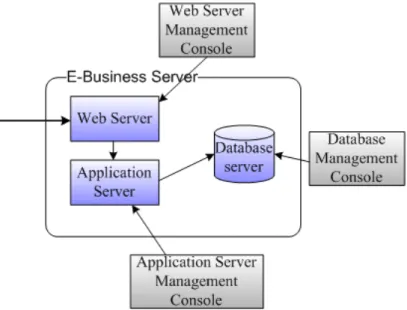
separates the application into the presentation tier, the business logic tier and the data tier. Under this architecture, the system is usually composed of many components. Take an E-Business system as example. An E-Business system may comprise of a web server, an application server and a database server. As shown in Figure 3.4. The administrator of this system would have to operate three systems with three different management interfaces. If the system needs to separate the transaction records from merchandise records for security issue, another database server may be created to store the transaction. Thus, the administrator would have to operate versatile management interfaces, which add the complexity of management.
Java Management Extension (JMX)[14] is a technique to solve such a problem. JMX is defined in JSR 3[23] and JSR 160[1] of Java Commu-nity Process. The JMX specification defines architectures, design patterns, and API that developers can follow to implement a management system in Java language. Developers can develop a distributed middleware system that integrates management systems from different kind of systems. System ad-ministrators can have a united management interface to manage each system resource. After integration by JMX, the system illustrated in Figiure 3.4 would transform into system as Figure 3.5:
Figure 3.5: The scenario after JMX implemented
3.2.2
Architecture
JMX architecture is composed of several layers: • Instrumentation level
• Agent level
• Distributed service level
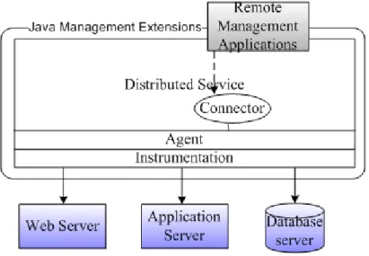
• Additional management protocol APIs Figure 3.6 illustrates the architecture:
The instrumentation level provides specification for implementing JMX manageable resources. A JMX manageable resource can be an application, a service, a device, etc. The resource is wrapped into a Java object called Man-aged bean (MBean). MBean provides an interface which includes attributes and operations. By implementing the attributes and operations the MBean provides, the manageable resources can be managed by JMX-compliant ap-plications. MBeans are designed to be simple, flexible and easy to implement. Developers of applications, services, or devices can make their products man-ageable in a standard way without having to understand or invest in complex management systems.
The instrumentation level also specifies a notification mechanism. This allows MBeans to send notification events to components of other levels.
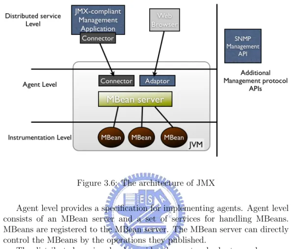
Figure 3.6: The architecture of JMX
Agent level provides a specification for implementing agents. Agent level consists of an MBean server and a set of services for handling MBeans. MBeans are registered to the MBean server. The MBean server can directly control the MBeans by the operations they published.
The distributed services level provides the protocol adaptor and connec-tor interfaces for implementing JMX managers. The JMX manager operates the MBean server in the agent level through the protocol adaptors or the con-nector. The administrator can have a unite management interface to manage messages sent from JMX agents, or distribute management information to JMX agents.
Additional Management Protocol APIs are developed as separated JSRs. For example, SNMP manager API provides a set of API to help develop tools of SNMP management application. By developing an SNMP manager and implementing it as an MBean, it can replace SNMP management applications on legacy systems.
3.3
Instant Messaging and Presence
Technolo-gies
Instant messaging and presence service (IM&P service)[20] is a service which can exchange literal messages between two users. The IM&P service also pro-vides presence information of a user. User can grasp the status information of other users on his roster (a buddy list). User can send instant message to his buddy if his buddy is online. The buddy can received the instant message immediately and they can begin to start a chat.
3.3.1
Brief History
The use of IM&P service would start with the UNIX system. Users fetch the status of a certain account by the command “finger”, then sending literal message to him by the “talk” command. The instant messaging capabilities were limited to plain text message. The presence information was limited to the last time a user accessed the account and the location. Internet relay chat (IRC)[11] was introduced to provide real time conversation among users anywhere in the world who were connected to a public network. Users can join and leave a chat room at anytime. Users in the chat room can receive message sent from other members in the chat room. IRC also provides a service for members to initiate a private communication between two users. ICQ (“I Seek You”)[10] was introduced that enabled users to chat simultane-ously over the internet without joining a chat room. Users are identified by a Universal Internet Number (UIN). Users can add other users’ UIN into the roster to fetch their status. It was so convenient that ICQ had 27000 users with a growth rate of 100 percent per week after introduced for two month. Microsoft MSN Messenger[16] and Yahoo Messenger[17] were both released hereafter. Instant messaging service became a field where large corporations were developing proprietary code, which were not interoperable. In 1998, Jabber project[12] was initiated to build an IM client and server that can interact with the various proprietary systems.
3.3.2
General Model of Presence and Instant
Messag-ing
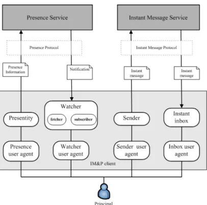
IETF IM&P Protocol (IMPP) working group propose a general model to help the development on any IM&P system. Figure 3.7 illustrated the model:
• Principal: People, groups and/or software outside the system that use the IM&P system.
• Presence service: Receives and distributes presence information. • Instant message service: Receives and send instant message. • Presentity: Provides presence information to the presence service. • Watcher: Receives presence information distributed from presence
service. There are two kinds of watchers, called fetchers and sub-scribers. A fetcher simply requests the value of some presentity’s pres-ence information; a subscriber requests notification from the prespres-ence service of future changes in come presentity’s presence information. • Sender: Sends instant messages to the instant message service. • Instant inbox: Receives instant messages from instant message
ser-vice.
• User agent: Inclusive of user agent, watcher agent, sender user agent and inbox user agent. A principal interacts with the system via one of several user agents.
Figure 3.8 illustrates how a IM&P work in this model:
In Figure 3.8 (a), when Juilet changes her status to “Busy”, the status in presentity changes from “online” to “Busy”. Presentity delivers the pres-ence information to the prespres-ence service. If Romeo has subscribed Juliet’s presence, he will receive the notification from the presence service.
In Figure 3.8 (b), when Juliet sends an instant message to Romeo, the sender will send the instant message service to the instant message service. The instant message service will deliver the instant message to Romeo’s in-stant inbox.
3.3.3
Extensible Messaging and Presence Protocol
Extendible Messaging and Presence Protocol (XMPP)[21] is an XML-based protocol for instant messaging and presence service defined by IETF. It is the core protocol of the Jabber Instant messaging and Presence technology.XMPP defines the structure of data exchange, which is represented in XML format. The main job of XMPP is processing XML stream (A con-tainer between two nodes in the internet to exchange XML elements) and the exchange of stanzas (an unambiguous unit of structured information that has a start and an end).
Figure 3.8: The message flow of an IM service. (a). Presence service (b). Instant messaging service
XMPP specification follows the client-server model. When a client wants to connect to the server, first of all, he negotiated a stream to the server. The stream is unidirectional from the client to the server. In order to enable information exchange from the server to the client, the server negotiates another stream back to the client. Then both the server and the client are free to send an unbounded number of XML stanzas over the stream. If the client address a stanza to a person in another domain, its server negotiates a server-to-server stream with the foreign domain, and send the stanza over that stream. As a result, the client can send stanzas to any other client under the public XMPP network.
XMPP defines three core stanza types:
1. <message/>: the stanza can be seen as a “push” whereby one entity pushes information to another entity. Usually used when two users send the instant message to the other. <message/>also used to response the error when last <message>stanza transmitted error.
2. <presence/>: used to represent a user’s presence status (online, busy, offline, etc) on the Jabber network.
3. <iq/>: IQ (info/query) stanzas provides a request-response mecha-nism, similar to HTTP, that lets entities make requests and receive
Figure 3.9: A scenario of the Jabber service
responses with each other. IQ interactions are usually used in contact-list management.
Figure 3.9 illustrates a user named [email protected] how to make a connection to the user named [email protected]:
First, Romeo login by negotiating a stream with montague.net. This step includes authentication, channel encryption, and other preliminaries. Then, Romeo get his contact list by exchange <iq/>stanza with montague.net: <iq type=’get’ from=’[email protected]/pda’>
<query xmlns=’jabber:iq:roster’/> </iq>
Montague.net responses:
<iq type=’result’ to=’[email protected]/pda’> <query xmlns=’jabber:iq:roster’>
<item jid=’[email protected]’ />
<item jid=’[email protected]’ /> </query>
</iq>
Then, Romeo sends his status to montague.net that montague.net can broadcast his status to Romeo’s contacts:
<presence from=’[email protected]/pda’ /> Montague.net send Romeo’s status to his contacts: <presence from=’[email protected]/pda’
to=’[email protected]’ />
<presence from=’[email protected]/pda’ to=’[email protected]’ />
If they are online, Romeo’s contacts return their presence to Romeo: <presence to=’[email protected]/pda’
from=’[email protected]/balcony’ /> <presence to=’[email protected]/pda’
from=’[email protected]/home’ />
If Romeo sends message to Juliet, the stanza would be: <message from=‘[email protected]/pda’
to=‘[email protected]’ > <body> Hi! </body>
</message>
Romeo can also send unbounded number of stanzas during this session to edit his conta1ct list, change his status, etc.
Chapter 4
Design
4.1
Requirement
The management of wireless network in NCTU campus is handing over to each department, as describe in previous chapter. In this architecture, each wireless administrator can know the status of wireless network in only the local area. Nobody can have an overall acquaintance with this campus.
Moreover, when there are some errors occur on the access points, for example, the access point crash due to overheat. The period between the access point crash and the administrator recognizes the situation, go to the position where the failed access point and restart the access point fixing it up. Users in this area can not use the wireless internet through this access point. It is a matter of wireless service quality. The way administrators acknowledging the error may from users who can not access the wireless internet and complain to the administrator by face or indirectly by telephone. Access points will never response the failure. Therefore, we need a monitoring system that administrators can receive notify immediately after the access point fails.
The construction time of access points in NCTU are not consistent in each area, and the manufacture and model of equipments are not consistent, too. This result in the different capability of the access points in NCTU. Take EC as an example, part of access points deployed in EC are manufactured from D-Link[8], which support SNMP; others are manufactured from ZCom[27], which do not support SNMP. Therefore, we can not design a system that totally based on SNMP, because we may not be able to manage these access points which do not support SNMP.
4.2
System Structure
Based on the requirement, we propose this architecture. The main compo-nents of this architecture are:
• Web server • Jabber server • Agent
• Database
Figure 4.1 shows the basic architecture.
4.2.1
Web Server
Web server is the front end interface in this architecture. It receives the request of the browser from the administrator and makes the correspond request to the remote agent. After the agent response, the web server trans-forms the output to the web page and response to the administrator.
The advantages of the web based management system are:
• There is at least one browser installed on almost every computer. By using the browser as the front end management interface, the admin-istrator can manage the access point in front of any computer with internet connected, no matter where the administrator is. The admin-istrator does not have to install a front end management application in the computer.
• The browser is an application which is independent of the management system. All management functions are provided by the web server. If there are some modifications in the management system, for example, adding a new management function, we only would alter the server side pages. There are no modifications in the client side.
The information that the web server can provide to the administrator may possibly as whether the status of one access point is. Furthermore, there should be a map of one building displayed on the browser and mark the position of access points. When there is an error detected, the position of the failed access point should be pointed out on the map. The administrator can go to the position pointed to do the recovery. The web interface should provide the function that can add/remove monitored access point to control the scale of managed devices
4.2.2
Jabber Server
When error occurs on the access point, there should be “someone” to tell the administrator about this problem. Agent is “someone”, and Jabber server is in charge of the warning message delivery.
Using Jabber to report the warning message, there are some advantages: • Instant message service is a real time service in the processing of mes-sage. When error occurs on the access point, the administrator will receive this event immediately if he is online.
• Administrator can see if the agent is online. If agent is online, it implies that the agent is working in condition; else if the agent is offline, the agent might not work normally. The administrator should check the status of the agent.
• Instant messaging service is a popular service in the recent years. It is very common that a instant messaging service client is working in the background at any time. The administrator would connect the instant messaging service, and set the status online, and then passively receive the notification. He need not connect to management system ad check the status of each access point.
• Jabber is a flexibly and scalable service. By relaying with a gateway, message can be redirected to other communication protocol such as SMTP or Short Message Service (SMS).
• Jabber client is an application which is independent of the management system, just like the browser. If there are some modifications about messaging notification in the management system, agent would only care about what message should send to the administrator. The client side would not do any modification.
4.2.3
Agent
Agent is the core of the whole management and monitoring system. The functionality of the agent would include:
• Detecting the status of access points by polling.
• Inform the administrator when error occurs on the access point. Due to the structure of access points deployed in NCTU campus, each administrator in the hotspot would setup an agent to consistently monitoring
the access points in this area. Web server would connect to the agents and make requests. Agent gets dynamic information (for example, the traffic of the access point) from access points directly, or static information (for example, the IP address of the access point) from the database. At last, the agent responses the information to the web server.
In the initialization time, the agent login to the Jabber server with a predefined account. The roster in this account includes all Jabber IDs of administrators. When error detected, the agent will send a message to all administrators on the roster. In the common days with no errors, the status of the agent would be informed to administrators through the presence of the agent.
Access points in each hotspot are associated in the bridge mode. Clients get IP address from DHCPD behind the access points, and access points are also assigned a private IP to preserve the IPv4 address. We can not connect to the access points directly from the public network. Therefore, the environment where the agent locates is a gateway that can connect both private network and public network.
We choose SNMP and ICMP[9] as the protocol to simultaneously manage these access points. To those access points that support SNMP, we try not to lose their capability. From the information SNMP agent provides, we can have a better understanding about the status of the access point. To other access points that do not support SNMP, we make ICMP echo requests by ping command to receive their ICMP echo response.
4.2.4
Database
Database provides the static information about all access points. For exam-ple, IP address, location, capability (ability to support SNMP), etc. When the agent starts up, it has to get the information to understand the targets it monitors and manages. As the ability of the management system grows up, the database may also help the agent to store the monitoring result. For ex-ample, the status of access points in the last two weeks. Combined with data mining techniques, those monitoring result can provide some information to administrators.
4.2.5
Summary
In this system, we need a web server to interact with the administrator; Database stores information like position, status of all access points; Agent consistently detects the status of the access point; Jabber server receives and relays message to administrators after agent detect the error. Web server,
database, and Jabber server do not need to exist in three physical machines. However, the agent must exist in the private network where access points locate, and it must be able to communicate with web server and Jabber server. So the agent usually exists in the gateway.
4.3
Program Structure
4.3.1
Agent
We choose to implement the agent with JMX.
First of all, we implement a MBean server. MBean server will login to the Jabber server when the MBean server is created. Then MBean server creates a RMI connector server to listen to RMI connection. We can connect to the MBean server in two ways: The connection can be set by RMI connector or directly or locally connect to the MBean server. The first method is suitable for our use. But in some occasional case (for example, the network connection fails). Administrators can connect to MBean server at the local machine to configure the MBean server.
We have to implement MBean for each access point. MBean server queries the database for the information of access points, create the corresponding MBean for each access point, ant then register them to the MBean server. The attributes of the MBean include IP address, position, etc. Operations of the MBean provide the function to detect the access point, for example, make a SNMP request to a access point that supports SNMP. If the destination access point does not response. MBean will send notification to MBean server. MBean server will handle the notification. In this case, MBean server will send a warning message to the administrators on the roster.
4.3.2
Web Structure
We choose Apache Tomcat[25] as our web server in the system. Apache Tomcat is a servlet container based on servlet and JavaServer Pages (JSP) specification. It provides an environment for Java code to run in cooperation with a web server. We implement JSP to produce dynamic web page as the front end interface that can interact with administrators.
To write a more maintainable code, we choose the model 2 Model-View-Controller (MVC) design pattern to implement the management console. MVC model is often applied in the GUI application or enterprise web appli-cations. It separates the program into three components:
Figure 4.2: The program structure of wireless monitoring system • Model: represents the business logic layer of the application. It
pro-vides data processing, database connection and produce data, etc. • View: represents the presentation layer of the application. It provides
user interface which the user can input data, and represents the result after processing the input data.
• Controller: process users action, determine the data from the view and deliver to the designated business logic, then forward to the view displaying the result.
We choose the appropriate implementations according to the functional-ity. JavaBean is an appropriate technology to design the model; JSP page is used to design the presentation of HTML page; the controller is implemented by servlet. The whole architecture is shown in Figure 4.3.
There are several advantages in the MVC design pattern:
1. There is no real processing happening in the view; it serves only as a way to output data. Web page designers do not need to consider the program logic; they only have to think about the presentation of the web page.
Figure 4.3: MVC design pattern
2. The model component represents only the data. The data returned by the model is display-neutral, meaning that the model applies no formatting. So a single model can provide data for any number of display interfaces. This reduces code duplication because model code is written only once and is then reused by all of views.
3. The controller controls the whole processing flow which reduces many conditional codes in the view components.
By leading the MVC pattern into our system, we use JavaBean to com-plete the interactions with the MBean server. JavaBean connects the RMI connector server which MBean server created through a connector. After connection complete, JavaBean can remotely control the MBean server. It can invoke MBean to execute operations hold the result. The controller for-wards to the JSP page then JSP request and formats the result and then response to the administrator. Figure 4.4 describes the components.
4.3.3
Jabber
There are many Jabber services provided by organizations around the world. We can choose a Jabber client, configuring an IP address of one Jabber server and user the Jabber service for free after registration. But for privacy issue, we do not want to expose the message sent between administrators
Figure 4.4: The structure of the web based management console in the wire-less monitoring system
and agents to other network. In the other way, to preserve the integrity of the system, we provide the service.
There are many Jabber servers and clients listed in Jabber Software Foun-dation. Anyone of them is suitable for us. We choose Wildfire[26] as our Jabber server. Wildfire is a Jabber server implemented by Java language, so it is platform independent.
4.4
Summary
When the architecture is deployed in NCTU campus, we may have the sce-nario like Figure 4.5. In Figure 4.5, only part of hotspot in NCTU dis-played. Each hotspot is managed by one or more administrators. Assume the supreme administrators is in the Computer and Network Center, we set the web server and the Jabber server in the Computer and Network Center. According this architecture, the supreme administrator can make manage-ment request to each hotspot to get the information of access points in each hotspot (As the line in Figure 4.5). When the error is detected, the agent in that hotspot would send message back to the administrators (As the dotted line in Figure 4.5). In this way, we can have overall understanding about the wireless problems in NCTU campus and get the warning in real time.
Figure 4.5: The scenario when deploying the wireless monitoring system into NCTU
Chapter 5
Implementation
This chapter we introduce the implementation according to our design in last chapter. We will introduce our implementation in each component and describe the functions in detail.
5.1
Agent
The implementation of the agent consists of two parts: • MBean
• MBean server
5.1.1
MBean
A MBean object represents a access point in the architecture, so the at-tributes and operations in the MBean are related to access points. We im-plement standard MBean as our MBean. To define a standard MBean, we have to write a Java interface named AccessPointMBean:
public interface AccessPointMBean { public String getIp();
public boolean getSupportSnmp(); public int getPort();
public String getCommunity(); public int getStatus();
public String getFloor(); public int getPosX(); public int getPosY();
public String getLocation(); public String getSnmp();
public void setLocation(String location); public void setCommunity(String c);
public void setFloor(String floor); public void setIp(String ip);
public void setPort(int port); public void setPos(int x, int y);
public void setSupportSnmp(boolean support); public void setStatus(int s);
public void pingFailureTest(); public void snmpFailureTest();
public void setSnmpQuery(String oid); }
Each method in the interface defines a attribute or a operation. These attributes and operations follow a design pattern. According to JMX specifi-cation, a method whose name started with“get” and return value is not void is called “getter”. For example, getIp() is a getter which gets the attribute named“Ip”. A getter should return a value with the same type as the corre-sponding attribute; A method whose name started with “set” and whose one parameter is called “setter”. For example, setIp(String s) is a setter which sets the attribute name “Ip” to a string s. An MBean interface consists of named and typed attributes that are readable and possibly writable, and named and typed operations that can be invoked by the applications that are managed by the MBean. In our example, snmpFailureTest() in Access-PointMBean is an operation; An attribute with only getter but no setter means that the attribute is readable and not writable. We write Access-Point class which implements AccessAccess-PointMBean. Each AccessAccess-Point object is an MBean in the architecture and it represents an access point, because it communicates directly to the access point. One of the communications is to request an OID value through SNMP. We defined the methods list blow to get a OID:
public void setSnmpQuery(String oid); public String getSnmp();
setSnmpQuery() set the OID attribute we want to query, and getSnmp() makes get request to the access point.
We include a library named JoeSNMP[15] to be the SNMP engine. JoeS-NMP is an open source Java SJoeS-NMP class library. We wrote a SJoeS-NMP client that makes SNMP get request. As shown in Figure 5.1:
Figure 5.1: Basic components of joesnmp API
First, we create a SnmpPeer by an IP address for the remote SNMP agent. One SnmpPeer represents one agent. Then we define the parameters to SnmpPeer which include SNMP port, Timeout delay, retries, SNMP ver-sion and community. A SnmpSesver-sion has to be created for the SnmpPeer. SnmpSession creates a SnmpPortal thread that will receive all response from the remote agent. It also creates a SnmpVarBind array to hold all SNMP requests.
We implemented a get-request by the following steps.
1. SnmpSession.send() will send a request. It’s a non-blocking request which will create a new thread to send request and handle retries and timeout.
2. Call Session.wait()
3. When SnmpSnmp receive the response from remote SNMP agent, Sn-mpHandler.snmpReceivedPdu() will handle the response. OID value in the response is abstracted and call Session.notify() to restart the thread waited in step 2.
4. If timeout or other mistakes happen, SnmpPeer will still callback to SnmpSession and call snmpTimeoutError() or snmpInternalError() in SnmpHandler.
getSnmp() in the AccessPoint class use above steps to get SNMP response. SnmpChecker class make a SNMP get-request to the designated device and check to see if the SNMP can work correctly according to the response from the SNMP agent. AccessPoint class will call SnmpChecker to check the status of the device in snmpFailureTest(). If the access point does not response, AccessPoint will send a notification to its MBean server. The
MBean server will handle the event. For the access points that do not support SNMP, if we want to get its status, we can only send ICMP echo request to them and get their ICMP echo response. Because the “ping” command is provided in almost every system, we invoke our request by executing the ping command in the system and judge the status of the access point from the output of ping command. If the output is like “request timeout”. AccessPoint will send a notification to the MBean server. The MBean server will handle the event.
5.1.2
MBean Server
The implementation of the MBean server includes: 1. Login to the Jabber server
2. Create and Register AccessPoint MBeans 3. Create the connector server
4. Failure testing
After the MBean server we named AgentMBeanServer is initialized, it will login to the Jabber server. We implement a Jabber client called the Jab-berClient. JabberClient imports the XMPP API provided by Jivesoftware. The relateds actions are illustrated as Figure 3.9 and Figure 5.2:
XMPPConnection conn = new XMPPConnection(server); conn.login(user, password);
roster = conn.getRoster();
The account is we pre-registered on the Jabber server. We also add administrators’ Jabber account to the contact list of this account.
The JabberClient implements MBean and is registered to the MBean server. The created MBean is registed to the MBean server with an object name. The object name is an identifier of an MBean. Each object name uniquely identifies an MBean within an MBean server. Management appli-cations use this object name to identify the MBean on which to perform management applications. An object name consists of two parts:
• Domain: provides a structure for the naming space within a JMX agent. • Key properties: enable us to give a unique name to the MBean of a
Figure 5.2: Actions of the JabberClient after booting the agent String representation of an object name has the following syntax:
[DomainName]:property=value[,property=value]*
In our implementation, we define the object name of the JabberClient as: Default Domain:type=JabberClient
Besides sending messages to administrators, JabberClient also needs the ca-pability to receive notifications. After AccessPoint sends a notification, Jab-berClient receive the notification and activates handleNotification() which sends the message to all administrators on the roster:
for (Iterator i = roster.getEntries(); i.hasNext();) { RosterEntry anEntry = (RosterEntry) i.next(); Chat chat = conn.createChat(anEntry.getUser()); Message message = chat.createMessage();
message.setBody(msg); chat.sendMessage(message); }
Figure 5.3: Initialization of AccessPoint MBeans
We create an MBean object for each access point. As shown in Figure 5.3. The information about access points is fetched from the database.
In our implementation, we define the object name of each MBean as: Default Domain:type=AccessPoint,index=[0-9]*
Where the key property “index” makes the MBean can store in an array and the MBean server can access each AccessPoint MBean with a loop.
After all MBeans are created and registered, in order to make a connection through the connector by the administrator, the MBean server creates a connector server:
JMXServiceURL url = new JMXServiceURL(
"service:jmx:rmi:///jndi/rmi://localhost:9999/server"); JMXConnectorServer cs =
JMXConnectorServerFactory.newJMXConnectorServer( url, null, mbs);
cs.start();
When start() is called, the connector server start to listen to the request from the client on the port 9999.
At last, the MBean server start polling each MBean and invoke the MBean the snmpFailureTest() and pingFailureTest(). In the beginning of each loop, The MBeanServer will query all AccessPoint MBeans by their object names(As step 3 in Figure 5.3).
The object name can be used as pattern matching with the following syntax:
1. * matches any character sequence, including an empty one 2. ? matches any single character.
For example, the following object names:
MyDomain:description=Printer,type=laser MyDomain:description=Disk,capacity=2 DefaultDomain:description=Disk,capacity=1 DefaultDomain:description=Printer,type=ink • “*:*” will match all objects
• “MyDomain:*” will match all objects in the domain MyDomain. • “??Domain:*” will match all objects in the domain
• “*Domain:description=Printer,type=laser,*” will match: MyDomain:description=Printer,type=laser and
DefaultDomain:description=Printer,type=ink The MBean server uses the object name:
DefaultDomain:type=AccessPoint,*
to get all the AccessPoints MBean registered on the MBean server.
Querying the AccessPoint MBean in the beginning of each polling loop is efficient when a new access point is added by the administrator. The MBean server will not have to be restarted.
5.2
Web
The management interface in the manager side includes several parts: 1. Choose to enter an agent
Figure 5.4: Agent class diagram 3. List the detail information of an access point 4. add a new access point
5. delete an access point
The first page of management console is a list that the administrator can choose to enter an agent. In this page, the web page needs to know where the agents are, what their name is and how to contact them. The information must be provided by a database. The database needs to store at least the IP address of the agent, and the information of an agent’s database. Those data may be used after entering into the following web pages, so we store the data into a list of JavaBean named Agent. Then the JSP page accesses each Agent and lists them in the web page. Figure 5.4 is a class diagram of the Agent JavaBean.
When the administrator decides to enter the chosen agent, the button makes a request to the servlet named ListApServlet. ListApServlet will first make a connection to this agent:
MBeanServerConnection mbsc = null;
JMXServiceURL jmxUrl = new JMXServiceURL(url); JMXConnector jmxc = JMXConnectorFactory.connect(jmxUrl, null); //Get an MBeanServerConnection mbsc = jmxc.getMBeanServerConnection(); ... }
This connection is stored in the Agent JavaBean that other servlet or JSP page can operate the Agent by this connection. ListApServlet create an AccessPoint JavaBean for each access point. The information in the AccessPoint JavaBean is got from the AccessPoint MBean:
String ip = mbsc.getAttribute(
(ObjectName)mBeanNames[i], "Ip").toString(); AccessPoint ap = new AccessPoint();
Ap.setIp(ip);
AccessPoint JavaBean is existed in an array and stored in a session. Be-sides AccessPoint JavaBean, there are many other information related to this agent. They are all stored in the session, and in this way the web server can understand which agent the administrator enters and have appropriate operations in the following pages.
ListApServlet then forwards to a JSP page (list-ap.jsp). The JSP page requests the AccessPoint JavaBean and formats the return values to a web page.
The detail information about an access point provided so far included the position of this access point which represented in a plan graph. The basic SNMP information is also provided for an access point which supports SNMP.
We adopt an applet to present the plan graph. According to the param-eter tag, the applet can show the appropriate plan this agent resides. The location of this agent resides is also labeled in the plan, and different status of this agent will labeled with different colors. As in Figure 5.5, the access point is labeled in white when the status of the access point is normal and red when abnormal.
The parameters in the applet tag are provided bye PositionServlet. Po-sitionServlet fetches the designated AccessPoint JavaBean according to the
Figure 5.5: Labels of access points on the plan. White lebel indicates teh normal access point red label indicates the abnormal access point.
administrator requests, and forward to the JSP page. The JSP page accesses this AccessPoint JavaBean and output the HTML code as:
<applet code="mapapplet.MapApplet.class"
width=700 height=600 codebase="/mvc_client/"> <param name="image" value="../image/EC.png"> <param name=x0 value=416 >
<param name=y0 value=195 > <param name=s0 value=0 > </applet>
As for SNMP information, due to the private MIBs provided by each access point manufacture, it is difficult to support those private MIBs. In addition, the information SNMP can provide is very rich, if too many unnec-essary information presented in a page, the administrator may feel confused. So we provided only the basic public MIB data and an interface that the administrator can input and query the OID in this access point.
DetailServlet receives the SNMP request and fetch the designated Ac-cessPoint JavaBean according to the administrator requests. Then control the MBean server to invoke a snmp-get method. After receiving the results, DetailServlet forwards to the JSP page to format the output.
String domain = mbsc.getDefaultDomain(); ObjectName name =
new ObjectName(domain+":type=AccessPoint,IP="+ip); Object[] params = {oid};
String[] signature = {"java.lang.String"}; String result =
(String)mbsc.invoke(name, "getSnmp", params, signature); AddApServlet is in charge of adding an access point. AddApServlet di-vided the functionality into three stages:
1. Input the IP address, is support SNMP, the location in which floor, etc.
2. Confirm the input
3. Add the data into the database, and register the access point to the MBean server.
AddApServlet have to deal with each stage and forward to different JSP pages according to different stages. As shown in Figure 5.6:
The initial stage is “INPUTDATA”. AddApServlet forwards to add-1.jsp. After the administrator fill in the form and press the submit button, the stage is come in to “CONFIRM” stage. AddApServlet forwards to add-2.jsp and list the data that the administrator has filled. After the administrator press the submit button, the stage comes to “COMPLETE” stage.
In “COMPLETE” stage, AddApServlet request the MBean server to cre-ate a new AccessPoint MBean and register it to the MBean server. Then AddApServlet makes a SQL query to add a row about the access point to the database. At last, AddApServlet forwards to add-complets.jsp to show the “add success” page if all the adding action are complete, or forwards to add-fail.jsp to explain why the add action fails.
DeleteApServlet is in charge of deleting an access point. Like AddApServlet, DeleteApServlet divided the functionality into two stages:
1. List the access points for the administrator to choose the deletion. 2. Deletes those access points and un-registers those access point from the
MBean server.
The implementation is similar to AddApServlet, but the differences are the query String and un-registration actions:
Figure 5.7: Sequence of deleting access points
5.3
Database
When the system boots, the MBean server needs to know who will be mon-itored and managed. This information is provided by the database. We use MySQL as our database server. MySQL provides MySQL Connector/J[7]. MySQL Connector/J is a java driver which translates JDBC (Java Database Connectivity) call into the communication protocol used by MySQL database. Our system implement the AgentMBeanServer class that uses Connector/J to create a connection to MySQL and fetch the information of access points. In this system, There are at least two databases exists in different loca-tions:
1. Web server side: In the beginning of the management console does not know where the agents are. Such information is provided by this database.
2. Agent side: As described before, stores the access point information. Web server side database created a table named agents. The columns in agents included:
• location: stores the location ID where the agents resides. Used as the primary key in this table.
Field Type Null Key Default Extra location varchar(10) no PRI NULL
ip varchar(50) no NULL db ip varchar(50) no NULL db name varchar(20) no NULL db user varchar(20) no NULL db passwd varchar(50) no NULL Table 5.1: Database schema of agent • ip: stores the IP address of this agent.
• db ip: stores the IP address of the database that the agent uses. This data if used when the agent make a connection to the database, so if the database is on the same physical machine as the agent, this field should be “localhost”.
• db name: the database name that the agent uses.
• db user: the user name when the agent login to the database. • db passwd: the password when the agent login to the database. We create two tables, apinfo and building:
• Apinfo: Stores all information of access points.
• Building: Stores the information about the building in the campus. The columns in apinfo should include:
• no: Index of the access points. Used as the primary key in this table. • building: The building name where this access point seat on.
• floor: Indicate which floor is the access point on.
• pos x: The x-coordinate where the access point is on the map. • pos y: The y-coordinate where the access point is on the map. • image: Image file name about the plan map of this building • supportSNMP: Indicate if the access point supports SNMP.
Field Type Null Key Default Extra no int(10) unsigned no PRI 0 auto increment building varchar(20) no NULL
floor varchar(20) no 0 pos x int(10) unsigned no 0 pos y int(10) unsigned no 0 image varchar(20) no NULL supportSNMP tinyint(1) no 0
ip varchar(30) no NULL
port int(10) unsigned no 161 community varchar(30) no public status int(11) unsigned no 0
Table 5.2: Database schema of apinfo Field Type Null Key Default Extra id varchar(20) no PRI NULL
floor num int(11) no 0 image varchar(20) no NULL
Table 5.3: Database schema of building • ip: The IP address of this access point.
• port: If the access point supports SNMP, what port does it use. • community: The read community of this access point.
• status: The status of this access point. The columns in building should include:
• id: The building ID. For example, Lib represents the library. Id used as the primary key in this table.
• floor num: Number of floors in this building • image: The plan map of this building.
5.4
Analysis
This system implements the approach we propose. It is capable of monitoring the access pints. However, behind this approach, how many costs has it pays?
Figure 5.8: Architecture of JConsole
How many access points can this system monitor? This is what we need to know.
5.4.1
Tool
The Java 2 Platform, Standard Edition (Java SE) 5.0 release provides com-prehensive monitoring and management support. JConsole is a Java Moni-toring and Management Console tool that is included in JDK5.0[13]. It is a JMX application-compliant monitoring and management tool that uses the extension instrumentation of the Java virtual machine to provide information on performance and resource consumption running on the Java platform.
Figure 5.8 shows how a JConsole can monitor and manage the application. In Java 5.0 release, the Java virtual machine (JVM) is highly instrumented for monitoring and management. We can use JConsole to connect the plat-form MBean server and get attributes of the Java virtual machine through its registered MBeans. In the same way, applications can create their own MBeans and register them in the MBean server. JConsole can also connect to the MBean server and management the applications.
As our agent program is implemented with JMX, JConsole is a good tool to estimate for the performance of the agent.
First, we want to measure the resource usage when an agent starting to resolve our problem.
We think that the number of access points is an important reason that affects the amount of usage in an agent. As a result, we design several experiments to estimate the resource usage. We estimate the system resource
usage when the system is monitoring 0, 24, 48, 72, 96, and 300 access points respectively. The system resource including:
• Memory usage • Number of threads • Number of classes
As for the reason that the system needs more resources to process when there is no response from the access point, we measure the worst case — which means all of access points are out of order in the system. We choose the 10.0.x.x IP network to define the IP addresses of the access points, but in fact these IP addresses are not being used and will not response to the monitoring system.
Second, we measure the resource variations when the administrator makes requests through the web client. The administrator makes the following requests to the agent monitoring 96 access points:
1. List all access points 2. Add an access point 3. Delete an access point
4. Show the position of an access point on the plan 5. Make 5 SNMP get requests
Then we recorded the variations of class loading, number of threads and heap memory usage.
5.4.2
Analysis Result
The monitoring system is executed under the following system:
• Java Virtual Machine: Java HotSpot(TM) Client VM version 1.5.0 05-b05
• Operating system: Windows XP 5.1 • Architecture: x86
• Number of processors: 1