Performance assessment and controller design for
unknown systems based on gain and phase margins
using modified relay feedback
Jyh-Cheng Jeng,∗ Hsiao-Ping Huang
Department of Chemical Engineering, National Taiwan University, Taipei 106, Taiwan
Abstract
A systematic procedure for performance assessment and PI/PID controller design based on modified relay feedback test is proposed in this paper. It can estimate the gain and phase margins of unknown systems on-line to indicate the appropriateness of the controller parameters. When the retuning of controller is found necessary, the proposed modified relay feedback scheme can be applied to tune the PI/PID controller based on specifications of gain and phase margins. Performance assessment and controller design can be done simultaneously, which ensures a good performance of the control system.
Keywords: performance assessment, relay feedback, gain margin, phase margin. 1. Introduction
The PID controller is widely used in chemical process industries because of its simplicity and robustness to the modelling error. However, many control loops are still found to perform poorly. Therefore, regular performance assessment and controller retuning are necessary.
Gain and phase margins have served as important measures of performance and robustness for the single-input-single-output (SISO) system. Because the calculation of gain and phase margins in traditional ways is very tedious, it is highly desirable to find a procedure for on-line monitoring of gain and phase margins. Recently, Ma and Zhu [1] proposed a performance assessment procedure based on modified relay feedback. Gain and phase margins are estimated by two relay tests. But their method may not give accurate results for processes with more complex dynamics such as process with right-half-plane (RHP) zero and oscillatory modes.
Controller designs to satisfy gain and phase margin specifications are well accepted in practice and in classical control. Åström and Hägglund [2] used relay feedback for automatic tuning of PID controllers with specification on either gain margin or phase margin, but not both. Some approximate analytical PI/PID tuning formulas have been derived to achieve the specified gain and phase margins [3]. Most of them use simplified models such as FOPDT and SOPDT model. For processes with more complicated dynamics, the resulting control systems may not achieve user-specified gain and phase margins exactly.
In this paper, a performance assessment procedure based on modified relay feedback test is proposed. It can on-line estimate the gain and phase margins for systems with both unknown process dynamics and controller parameters. The estimated
∗ Corresponding author. Tel.: 886-2-3366-3067; e-mail: [email protected]
W. Marquardt, C. Pantelides (Editors)
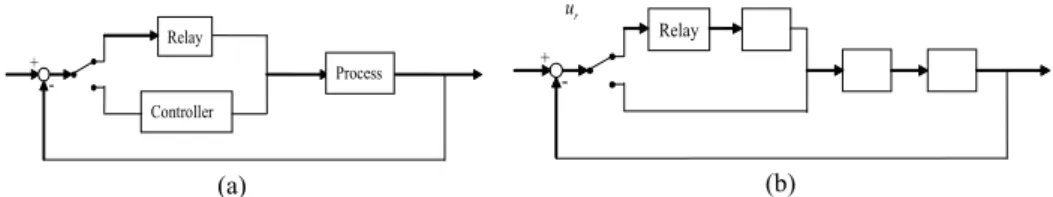
Relay + -r u Relay + -Controller Process (a) (b)
results can be used to indicate the appropriateness of the controller parameters. When the retuning of controller is found necessary, a similar procedure can be applied to tune the PI/PID controller based on the user-specified gain and phase margins.
2. Modified Relay Feedback Structure
The use of relay feedback for automatic tuning of PID controllers was first proposed by Åström and Hägglund [2]. The block diagram of the standard relay feedback system is as shown in Fig. 1(a). The system generates a continues cycling with a period Pu if it has a phase lag of at least
π
. The ultimate frequency from this relay feedback test is ωu = 2π/Pu and the ultimate gain can be approximately given by Ku = 4h/πa, where h is the relay output magnitude and a is the amplitude of limit cycle.For the purpose of performance assessment, a modified relay feedback structure is proposed as shown in Fig. 1(b) where Gc, G, ur and y are the controller, process, relay output, and process output, respectively. Moreover, a delay element,
e
−Δs, is embedded between the relay and the controller. Compared with the conventional relay feedback, the most important features of this modified structure are that the controller is always connected in line with the process and an additional delay is embedded. As a result, it can assess the performance of the closed-loop system by estimation of gain and phase margins on-line, as presented in the following section, to determine if a retuning of the controller is necessary.Fig. 1 (a) Standard relay feedback system (b) Modified relay feedback system
3. Performance Assessment
3.1. Estimation of Gain Margin
Consider the modified relay feedback system as shown in Fig. 1(b). For the estimation of gain margin, the delay
Δ
is set as zero. Let the loop transfer function be GLP(s) = Gc(s)G(s). The phase crossover frequency, ωp, of GLP(s) can be calculated byωp = 2π/Pp, where Pp is the period of the limit cycle. In addition, the amplitude of
GLP(s) can be approximately calculated by
G
LP( )
j
ω
p=
π
a h
4
[2]. However, the accuracy of such approximation is poor in some cases where the error may be as large as 20% [4]. For more accurate estimation,G
LP( )
j
ω
p can be computed based on Fourier analysis as:( )
Pp( )
j pt Pp( )
j ptLP p r
G
j
ω
=
∫
y t e
−ωdt
∫
u t e
−ωdt
(1) Therefore, the gain margin, Am, can be estimated as:( )
1
m LP p
3.2. Estimation of Phase Margin
When the estimation of gain margin is finished, the delay
Δ
is then set as a non-zero value in order to extract the frequency information of GLP(s) at other frequencies for the estimation of phase margin. With a given value ofΔ
, assume that the system oscillates with a period of P and then we have the phase of the system as:( )
{
}
{
( )
}
arg
sarg
LP LP
G
j
ω
e
−Δ=
G
j
ω
− Δ = −
ω
π
(3) where ω = 2π/P. To calculate the phase margin, the desired frequency is the gain crossover frequency, ωg, of GLP(s). Denote the desired value ofΔ
that makes the amplitude of GLP, at the corresponding oscillating frequency, equal unity asΔ
d and the period of the limit cycle is Pg. In other words, the gain crossover frequency of GLP(s) is equal to the phase crossover frequency of( )
sLP
G
s e
−Δ . In this case, Eq.(3) can be written asarg
{
G
LP( )
j
ω
g}
− Δ
dω
g= −
π
where ωg = 2π/Pg. Then, it follows that the phase margin,φ
m, can be estimated as:( )
{
}
arg
m
G
LPj
g d gφ
=
ω
+ = Δ
π
ω
(4) To find the value ofΔ
d, an on-line iterative procedure as the following is presented. Starting from an initial guessΔ
(0), the value ofΔ
is updated by( )i 1 ( )i ( )i
(
(
( )i)
1
)
LPG
j
γ
ω
+Δ
= Δ −
−
(5) whereγ
( )i>
0
is the convergence rate and(
( )i)
LP
G
j
ω
is computed by( )
( )
( ) ( ) ( ) ( ) ( ) ( ) ( )i ( )i j i i Pi( )
j it Pi( )
j it LP LP rG
j
ω
=
G
j
ω
e
−ω Δ=
y t e
−ωdt
u t e
−ωdt
∫
∫
(6)Notice that we have
Δ =
d0
ifA
m=
1
, and, in general,Δ
d increases asA
m andP
p increase. Thus, the value ofΔ
(0) is suggested as(
A
m−
1
)
P
p6
. In addition,γ
( )i is chosen as:(
)
(
(
)
(
)
)
( )i ( )i ( 1)i ( )i ( 1)i LP LPG
j
G
j
γ
= Δ − Δ
−ω
−
ω
− (7) which can make Eq.(5) have a quadratic convergence rate near the solution [2]. In each iteration, the value ofΔ
( )i is set until the output generates two or three oscillating cycles and then switch it to the next value just like an on-line adaptive scheme. When Eq.(5) converges, the resulting value ofΔ
is taken asΔ
d.3.3. Extension to Multi-Loop Systems
The proposed procedure can be extended to multi-loop control systems if the gain and phase margins are defined in the similar spirit as SISO system based on the effective open-loop process (EOP) [5]. The i-th EOP describes the effective transmission from the i-th input to the i-th output when all other loops are closed. With the formulation of EOP, the multi-loop control system can be considered as several equivalent SISO loops and the gain and phase margins of each equivalent loop can be estimated by sequentially using of the proposed modified relay feedback test.
4. Controller Tuning
4.1. Tuning of PI Controller
Consider the PI controller of
G s
c( )
=
k
c(
1 1
+
( )
τ
Is
)
. Denote the user-specified gain and phase margins asA
m* andφ
m*, respectively. For a given value ofΔ
, the parameters,k
c andτ
I, can be found to satisfy the specification of phase margin. In other words, they can be found such that the following two equations hold.*
or
2
* m gP
g mφ
= Δ
ω
=
π φ
Δ
(8)( )
( )
j g1
LP g LP gG
j
ω
=
G
j
ω
e
−ωΔ=
(9) However, the specification of gain margin may not be necessarily achieved by such obtained controller parameters. There exists a certain value ofΔ
which can make the gain margin of the resulting system meet its specification. Thus, an iterative procedure for tuning the PI controller using the modified relay feedback test is presented as follows:1) Starting with a guessed value of
Δ
, i.e.Δ
(0). 2) Adjustτ
I by the following equation:(
)
( 1) ( ) ( ) ( ) * 12
i i i i I IP
mτ
+=
τ
−
γ
−
π φ
Δ
(10)where
P
( )i is the period of limit cycle in the i-th iteration. Eq.(8) holds when Eq.(10) converges.3) Adjust
k
c by the following equation until it converges so that Eq.(9) holds,(
)
(
)
( 1) ( ) ( ) ( ) 21
i i i i c c LPk
+=
k
−
γ
G
j
ω
−
(11) whereω
( )i=
2
π
P
( )i andG
LP(
j
ω
( )i)
is computed by Eq.(6).4) Set
Δ =
0
and estimateA
m by Eq.(2).5) Check if the estimated
A
m equalsA
m*. If not, change the value ofΔ
by the following equation and go back to step 2) untilA
m=
A
m* holds.(
)
( 1) ( ) ( ) ( ) * 3 i i i i m mA
A
γ
+Δ
= Δ −
−
(12) The convergence rates,γ
1( )i ,γ
2( )i andγ
3( )i , are defined in the similar manner of Eq.(7). For FOPDT process, inserting a delayΔ
in the relay feedback loop approximately results in an increase of4
Δ
in the period of limit cycle. In order to improve the convergence of Eq.(10), it is desirable that2
π φ
Δ
m*= ≈
P
(
P
p+ Δ
4
)
. Thus, the initial guess ofΔ
is suggested asΔ =
(0)P
p(
2
π φ
m*−
4
)
4.2. Tuning of PID Controller
For the tuning of PID controller, a similar procedure can be applied. The PID controller transfer function is given as
G s
c( )
=
k
c(
1 1
+
(
τ
Is
)
+
τ
Ds
)
. The derivativetime,
τ
D, is usually chosen as a fixed ratio of the integral time,τ
I, asτ
D=
ατ
I. Researchers have recommended thatα
=
0.25
[2]. With this relation, the procedure for PI controller tuning presented in the previous section can be applied directly to tune the PID controller. Ifτ
D is not chosen as a fixed ratio ofτ
I, then the extra degree of freedom can be used for achieving another performance requirement.5. Simulation Examples
5.1. Example 1
Consider a control system with FOPDT process
G s
( )
=
e
−θs(
s
+
1
)
and PI controllerG s
c( ) 0.616 1 1 0.765
=
(
+
(
s
)
)
. Three different values of the process dead-time,θ
=
0.5, 1, 1.5
, are used for simulation. The estimated gain and phase margins together with the values ofΔ
( )i during iteration are shown in Table 1. The value ofΔ
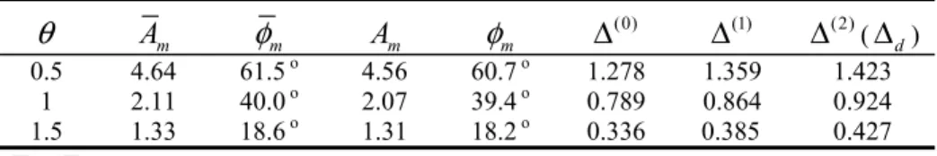
converges after two iterations. The output responses during the estimation procedure are shown in Fig. 2, where period I is for estimating gain margin and periods II to IV are for estimating phase margin.For the case of
θ
=
1.5
, the gain and phase margins are too small, so we retune the controller with the specifications chosen asA
*m=
2.5
andφ
m*=
54
o. The results converge after two iterations ofΔ
(Δ =
(2)2.239
), and the PI controller is obtained as(
)
(
)
( ) 0.424 1 1 1.008
cG s
=
+
s
. The actual gain and phase margins of this resulting control system areA
m=
2.49
andφ
m=
53.2
o, which are very close to the specified ones. The closed-loop responses before and after retuning are shown in Fig. 3.Table 1. Actual and estimated gain margin, phase margin in example 1
θ
A
mφ
mA
mφ
m (0)Δ
Δ
(1)Δ
(2) (Δ
d) 0.5 4.64 61.5 o 4.56 60.7 o 1.278 1.359 1.423 1 2.11 40.0 o 2.07 39.4 o 0.789 0.864 0.924 1.5 1.33 18.6 o 1.31 18.2 o 0.336 0.385 0.427 mA
,φ
m: actual gain and phase margins5.2. Example 2
Consider a process with RHP zero
G s
( )
= −
(
1
β
s
) (
s
+
1
)
3 and a PI controller( )
(
)
( )
1 1 2
c
G s
= +
s
, which are used for simulation in Ma and Zhu [1]. For the cases ofβ
=
1
andβ
=
0.1
, the actual gain and phase margins together with the estimated values by Ma and Zhu [1] and the proposed method are given in Table 2 for comparison. The proposed method can estimate the gain and phase margins more accurately.For the case of
β
=
1
, retune the PI controller with the specifications given as*
3
m
0 10 20 30 40 50 60 70 80 90 -2 -1 0 1 2 y (a) 0 10 20 30 40 50 60 70 80 90 -2 -1 0 1 2 y 0 10 20 30 40 50 60 70 80 90 -2 -1 0 1 2 Time y I II III IV I II III IV IV III II I (b) (c) 0 10 20 30 40 50 60 70 80 0 0.2 0.4 0.6 0.8 1 1.2 1.4 1.6 1.8 Time y Before retuning After retuning
Fig. 2 The output response during assessment (a)
θ
=
0.5
(b)θ
=
1
(c)θ
=
1.5
Fig. 3. Closed-loop responses (
θ
=
1.5
)(
Δ =
(2)4.961
), and the PI controller is obtained asG s
c( ) 0.32 1 1 1.524
=
(
+
(
s
)
)
. The actual gain and phase margins of this resulting control system areA
m=
3.12
ando
60.3
mφ
=
.Table 2. Actual and estimated gain margin, phase margin in example 2
Actual value Estimated [1] Estimated (proposed method)
β
mA
φ
mA
mφ
mA
mφ
m (2) dΔ = Δ
1 1.28 20.0 o 1.19 12.7 o 1.20 16.9 o 0.501 0.1 3.49 51.6 o 3.29 41.8 o 3.34 51.8 o 1.789 6. ConclusionsA systematic procedure for performance assessment and controller design based on modified relay feedback test is proposed. The proposed method can estimate the gain and phase margins on-line for systems with both unknown process dynamics and controller parameters. The estimated results can be used to assess the performance of the closed-loop system. When the retuning of controller is found necessary, a similar procedure can be applied to tune the PI/PID controller based on the user-specified gain and phase margins. Simulation results have shown that the proposed method is effective for processes with different kinds of dynamics.
References
[1] M. D. Ma and X. J. Zhu, Performance Assessment and Controller Design Based on Modified Relay Feedback, Ind. Eng. Chem. Res., 44 (2005) 3538.
[2] K. J. Åström and T. Hägglund, Automatic Tuning of Simple Regulators with Specifications on Phase and Amplitude Margins, Automatica, 20 (1984) 645. [3] W. K. Ho, C. C. Hang and L. S. Cao, Tuning of PID Controllers Based on Gain and
[4] W. Li, E. Eskinat and W. L. Luyben, An Improved Autotune Identification Method. Ind. Eng. Chem. Res., 30 (1991) 1530.
[5] H. P. Huang, J. C. Jeng, C. H. Chiang and W. Pan, A Direct Method for Multi-loop PI/PID Controller Design, J. Process Control, 13 (2003) 769.