國立交通大學
電子工程學系電子研究所碩士班
碩 士 論 文
密集小型基地台與裝置間通訊共存之干擾消除技術
Interference mitigation mechanism
for D2D communication
in ultra-dense small cell network
研 究 生:余俊宏
指導教授:黃經堯 博士
密集小型基地台與裝置間通訊共存之干擾消除技術
Interference mitigation mechanism
for D2D communication
in ultra-dense small cell network
研 究 生 : 余俊宏
Student: Chun-Hung Yu
指導教授: 黃經堯
Advisor: Ching-Yao Huang
國 立 交 通 大 學
電子工程學系電子研究所碩士班
碩 士 論 文
A Thesis
Submitted to Department of Electronics Engineering & Institute of Electronics College of Electrical and Computer Engineering
National Chiao Tung University in Partial Fulfillment of the Requirements
for the Degree of Master of Science
in
Electronics Engineering October 2014
Hsinchu, Taiwan, Republic of China
密集小型基地台與裝置間通訊共存之干擾消除技術
學生:余俊宏 指導教授:黃經堯 博士
國立交通大學
電子工程學系電子研究所碩士班
摘 要
在小型蜂巢式基地台被電信營運商們廣泛接受之後,布建高密度的小型蜂巢式基 地台相關的研究也逐漸被討論。同時裝置間的直接通訊也在 3GPP 也是個熱門的主 題,裝置間的直接通訊是個很直觀的概念,藉由直接通訊縮短距離與減少使用骨幹 網路的機會 ,同時也減少傳輸路徑的損耗達到提升訊噪比。但在高密度的小型蜂 巢式基地台與裝置間通訊共存時,系統效能是會逐漸被影響而下降的。在這篇論文 中,我們會針對高密度小型蜂巢式基地台對裝置間通訊在共通道情況下造成的干 擾,也提出方案解決不同裝置間直接通訊情境。提出的解決方法包含了不同的方式 觸發睡眠模式以及多點傳輸技術幫助一些隱性受害的使用者。在模擬結果部分我們 結合了兩種不同的方法並且有效的改善傳輸效能在高密度的小型蜂巢式基地台使用 裝置間直接通訊。但還有一點要注意的是,在這邊提供的方法是可以改善干擾問 題,但要在這樣的環境下能夠正常的通訊還是必須要有其他的方法來輔助,像是重 新分配通道這類的方法,結合不同的方法才能有效提升通訊的品質與問題。 iInterference mitigation mechanism
for D2D communication
in ultra-dense small cell network
Student: Chun-Hung Yu Advisor: Dr. Ching-Yao Huang
Department of Electronics Engineering
& Institute of Electronics
National Chiao Tung University
Abstract
After small cell concepts are widely accepted, researches in ultra-dense small cell de-ployment issues are investigated. At the same time, device-to-device (D2D) becomes a popular topic, discussed by 3GPP. Direct communication is an intuitive concept which can decrease the usage of backbone network and shorten the distance of transmission in order to enhance SINR performance. However, performance degradation will occur while ultra-dense small cells coexist with D2D. In this thesis, we will study the co-channel in-terference issue for D2Ds initiated in an ultra-dense small cell network. Solutions for solving different D2D transmission scenarios are proposed. The proposed solutions in-cluding the trigger of sleep-mode operation and joint transmission under multi-point (CoMP) network for potential victims caused by sleep-mode operation. From simulation results, we will identify the combination of two schemes can significantly enhance trans-mission performance in ultra-dense small cell network for supporting D2D transtrans-mission. However, operating in such an extreme case (co-channel transmission), the network will still require other methods like channel allocation or fractional transmission to meet con-ventional operation range for real transmission.
誌謝
時空飛梭,碩士生涯不知不覺就到了尾聲,研究所的生活十分充實學
習也非常的紮實。感謝黃經堯老師的耐心教導,研究中陷入泥淖時領導
我前進,同時也給我鼓勵與實質上的建議,讓我可以順利完成這段學業
並且穩紮穩打的學會科目。
同時還要感謝實驗室裡的勇嵐學長、烜立學長、建銘學長、理銓學長、
傑堯學長、東祐學長、峻安學長、仲煒學長、泓志學長平日在實驗室也
提供我研究或是學業上的幫助。感謝實驗室同學嘉宏,還有學弟士華、
顥晨、吳杰在實驗室的工作上也給予了幫忙與陪伴,讓事情得以順利進
行。
另外感謝我的朋友們,在我面對研究的難關時也總是給我鼓勵,不管
是低位單打、中興熱音、中興電機的好友們,都在我束手無策時給我建
議。最後的最後,要感謝我的家人爸爸、媽媽、妹妹還有我的女朋友斯
鈴給我支持以及鼓勵,讓我沒有後顧之憂才有辦法專心研究。
對於大家對敝人的關懷與照顧都永遠抱著感恩,若有需要幫忙之處我
也必當投桃報李,在這裡與大家分享這篇論文,希望和大家分享我的成
果。
謹誌
2014年, 國立交通大學, 台灣
iiiContents
摘 要... i Abstract ... ii 誌謝... iii Contents ... iv List of Tables ... viList of Figures ... vii
Chapter 1 Introduction ... - 1 -
Chapter 2 Background of HetNet and D2D ... - 2 -
2.1 Overview of LTE-A... - 2 -
2.2 Overview of Small Cell Networks ... - 3 -
2.3 Overview of CoMP ... - 4 -
2.4 Overview of D2D ... - 6 -
Chapter 3 System Model and Problem Formulation ... - 8 -
3.1 System Model in D2D Communication ... - 8 -
3.2 Problem Formulation ... - 10 -
Chapter 4 Issue & Proposed Solution ... - 13 -
4.1 Issue & Proposed Solution I ... - 13 -
4.1.1 Issue:Unnecessary Small Cell ... - 13 -
4.1.2 Proposed Solution:Small cell D2D state ... - 14 -
4.2 Issue & Proposed Solution II ... - 16 -
4.2.1 Issue:Victim from Small Cell ... - 16 -
4.2.2 Proposed Solution:Small Cell Grouping and Coordinate ... - 17 -
Chapter 5 System Level Simulation and Evaluation ... - 19 -
5.1 Simulator building – Initial Setting ... - 19 -
5.1.1 Some assumption ... - 19 -
5.1.2 Parameter setting ... - 19 -
5.2 Mechanism Evaluation I... - 22 -
5.3 Simulation Result I ... - 23 -
5.4 Mechanism Evaluation II ... - 30 -
5.5 Simulation Result II ... - 31 -
Chapter 6 Conclusion ... - 36 -
Reference ... - 38 -
List of Tables
TABLE 3-1NOTATION SUMMERY ... -12
-TABLE 5-1BASE STATION PARAMETER ... -19
-TABLE 5-2PATHLOSS BETWEEN NODES ... -20
-TABLE 5-3EXPERIMENT PARAMETER ... -20
-TABLE 5-4METHOD DESCRIPTION DETAIL I ... -22
-TABLE 5-5SINR COMPARISON I ... -30
-TABLE 5-6METHOD DESCRIPTION DETAIL II ... -31
-TABLE 5-7SINR COMPARISON II ... -35
List of Figures
FIGURE 2-1EXAMPLE FOR TDDLTE AND FDDLTE ... -3
-FIGURE 2-2EXAMPLE FOR HETNET ... -4
-FIGURE 2-3EXAMPLE FOR COMP ... -6
-FIGURE 2-4COMPARISON FOR JT AND CS/CB ... -6
-FIGURE 2-5EXAMPLE FOR D2DUE PAIRS USING BOTH UL/DL RESOURCE ... -7
-FIGURE 3-1SYSTEM MODEL FOR HETNET COEXIST D2D COMMUNICATION... -8
-FIGURE 4-1SCENARIOS ABOUT DIFFERENT D2D CASES I ... -14
-FIGURE 4-2SCENARIOS ABOUT DIFFERENT D2D CASES II ... -14
-FIGURE 4-3EXAMPLE FOR SMALL CELL SLEEP MODE ... -15
-FIGURE 4-4EXAMPLE FOR PROPOSAL D2D STATE IN SLEEP MODE ... -16
-FIGURE 4-5EXAMPLE FOR VICTIM APPEAR AFTER SMALL CELL TURN OFF ... -17
-FIGURE 4-6JT AND SC GROUPING IMPLEMENT TO ENHANCE VICTIM RECEIVE SIGNAL I ... -17
-FIGURE 4-7JT AND SC GROUPING IMPLEMENT TO ENHANCE VICTIM RECEIVE SIGNAL II ... -18
-FIGURE 4-8JT AND SC GROUPING IMPLEMENT TO ENHANCE VICTIM RECEIVE SIGNAL II ... -18
-FIGURE 5-1NETWORK DEPLOYMENT FOR 20SCS ... -21
-FIGURE 5-2NETWORK DEPLOYMENT FOR 25SCS ... -21
-FIGURE 5-3NETWORK DEPLOYMENT FOR 30SCS ... -21
-FIGURE 5-4REMAIN SCENARIOS... -22
-FIGURE 5-520SC AND 150UEDLSINR ... -24
-FIGURE 5-620SC AND 150UEDL THROUGHPUT... -24
-FIGURE 5-725SC AND 150UEDLSINR ... -25
-FIGURE 5-825SC AND 150UEDL THROUGHPUT... -25
-FIGURE 5-930SC AND 150UEDLSINR ... -26
-FIGURE 5-1030SC AND 150UEDL THROUGHPUT... -26
-FIGURE 5-1120SC AND 180UEDLSINR ... -27
-FIGURE 5-1220SC AND 180UEDL THROUGHPUT... -27
-FIGURE 5-1325SC AND 180UEDLSINR ... -28
-FIGURE 5-1425SC AND 180UEDL THROUGHPUT... -28
-FIGURE 5-1530SC AND 180UEDLSINR ... -29
-FIGURE 5-1630SC AND 180UEDL THROUGHPUT... -29
-FIGURE 5-1720SC AND 150UEDL THROUGHPUT... -32
-FIGURE 5-1825SC AND 150UEDL THROUGHPUT... -32
-FIGURE 5-1930SC AND 150UEDL THROUGHPUT... -33
-FIGURE 5-2020SC AND 180UEDL THROUGHPUT... -33
-FIGURE 5-2125SC AND 180UEDL THROUGHPUT... -34
-FIGURE 5-2230SC AND 180UEDL THROUGHPUT... -34
Chapter 1
I
NTRODUCTION
Device-to-device (D2D) communications have been added to LTE in 3GPP Release 12 [1] . Although cellular network deployments are nearly ubiquitous provide wide range of advance services and solve the increasing subscriber population, exploiting direct communication be-tween nearby mobile devices will still improve spectrum utilization, overall throughput, and en-ergy consumption, D2D-enabled LTE devices can also become competitive for fallback public safety networks that must function when cellular networks are not available, or fail.
3GPP has two group discussing this topic “SA” & “RAN”. [2] has discussed proximity-based service (ProSe) with device discovery, introduction for scenarios, use cases and require-ments for discovery of device-to-device(D2D). D2D discovery procedure, discovery signal and LTE-based design.
Usually, operators will focus on increasing deployment cell density. Such as [3] has dis-cussed low-duty operation femto BS. In a dense urban environments, own a short radio links is a traditional way for provide higher bit rates and higher energy efficiency when using small cell. However, deploying larger numbers of small cell occurs interference management prob-lem. We follow 3GPP conference and recent contribution document, D2D have many potential in different domain, such as public safety and commercial usage.
We consider a combinational system include small cell networks and D2D communication, combinational system verifies an advanced network. In this thesis, we will talk about current issue in LTE network and motivation of researcher to develop D2D technique in Chapter 2. Chapter 4 describes two issue briefly and solve two issue with our two proposal, we propose a novel on/off SC control mechanism and add in coordinated multi point (CoMP) since victim appears after we implement on/off control. Chapter 3 formulate the problem and simulation to verify proposal in Chapter 5 and evaluate in worst case. Chapter 6 will give a conclusion and several future work.
Chapter 2
B
ACKGROUND OF
H
ET
N
ET AND
D2D
Heterogeneous networks (HetNet) has been investigated in recent of years, operators realized the requirement of significant increasing of data. To provide significant performance leap in wireless networks and improving spatial spectrum reuse, deploy large amount of small cells overlaying the macro BS has been well known. HetNet unit include mix of macro BS, remote radio head and low-power node such as picocells, femtocells, and relays. After small cell con-cepts are widely accept by public, D2D have been added to 3GPP Release 12. Although D2D and small cell both offload network, D2D coexist with ultra-dense small cell can get what kind of benefit still need to verify.
2.1 Overview of LTE-A
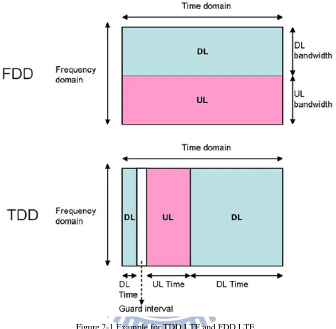
LTE-A (Long-term-evolution advanced) is a mobile communication evolution from LTE which was formally submitted as a candidate 4G system to ITU-T in late 2009 [4], and was standardized by the 3rd generation Partnership project (3GPP) in March 2011 as 3GPP Release 10. Nowadays, high speed mobile application is ubiquitous, LTE standard expect Downlink 100Mbps/Uplink 50Mbps in 20MHz frequency band with good QoS, even at the cell edge. However, frame structure has two totally different mode, frequency-division duplexing (FDD) and time division duplexing (TDD) [5]. The difference between TDD and FDD is shown as Figure 2-1 from Institute for Information Industry (III).
Figure 2-1 Example for TDD LTE and FDD LTE
2.2 Overview of Small Cell Networks
Small cells (SC) are an integral part of LTE networks. SC are low powered radio access nodes that operate in licensed and unlicensed spectrum unlike WiFi APs only in unlicensed band. When mobile operators struggling to fast increasing mobile data traffic, SC appear for more efficient use of radio spectrum and enhance signal strength by providing line-of-sight path or nearer signal source. In dense urban areas, base stations are deployed very close to each other, so small cells overlap with each other, too. Overlapping provide benefits when user (UE) moving due to handover and other reason but also cause interference for those UE who are not the desire receiver , 3GPP has proposed enhanced inter-cell interference (eICIC) for HetNet in
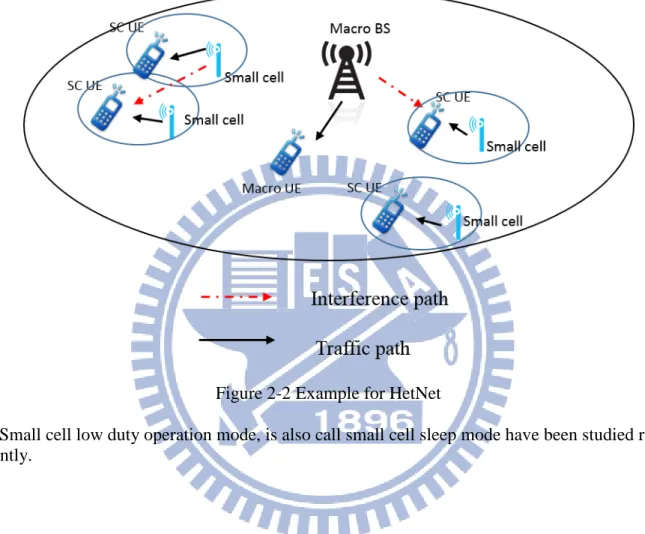
order to mitigate interference by allowing some special subframe called almost blank subframe (ABS) in macro BS frame configurations. Figure 2-2 shows inter-cell interference, consider a dense deploy small cell networks, HetNet will face more challenges due to irregular large amount of small cell.
Figure 2-2 Example for HetNet
Small cell low duty operation mode, is also call small cell sleep mode have been studied re-cently.
2.3 Overview of CoMP
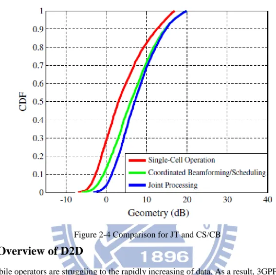
In order to mitigate inter-cell interference cause by dense SC, there are a lot of studies [6] working on this problem such as quasi-static resource allocation schemes. A well-known tech-nique is coordinated multi-point (CoMP) [7] processing which mitigate in-cell interference by coordinating the transmission of several geographically but well synchronized cells. CoMP transmission has two classes: Joint Transmission (JT) and Coordinated Scheduling/Beamform-ing (CB/CS). JT represent the case where two or more transmission points (TPs) are transmit-ting signal to a single device on the same time-frequency resource [8] and several studies [9], [7] have verified that JT has better performance than CB/CS, see Figure 2-4, so in this thesis
we include JT CoMP instead of CB/CS. In [8] is also mentioned previous studies for coherent JT but in some research [10] has evidence coherent JT is especially sensitive to imperfections of CSI so it would be premature to include it in the standard in Rel-11; nevertheless, it can still be implement in TDD by channel reciprocity. Non-coherent JT is not able to nullity interfer-ence across multiple TPs, the SINR at UE device could be boosted by non-coherent JT, too, but with area splitting-gain, as multiple TPs could instead schedule multiple separate UE devices. Only UE located on the coverage of edge of two TPs are able to get benefit from non-coherent JT.
Figure 2-3 Example for CoMP
Figure 2-4 Comparison for JT and CS/CB
2.4 Overview of D2D
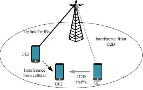
Mobile operators are struggling to the rapidly increasing of data. As a result, 3GPP is cur-rently investigation possible scenarios for D2D offloading in LTE networks, in [11] has dis-cussed 3GPP LTE traffic offloading onto WiFi direct. In [12], [13] has introduced scenarios, use cases and requirements for discovery of D2D proximity from 3GPP SA and RAN. Corre-sponding solution options and link budget based on current 3GPP evaluation are also provide. Device discovery and communication are basic two enabling D2D features to fulfill the need for the ProSe. ProSe has also been introduced in [14], [15], it mentions that we can further dis-cuss when UE may use DL resource due to enhance network capacity and throughput. In FDD LTE, DL spectrum is not able for UE, but TDD spectrum, studies of both UL and DL sub-frames are still open, see Figure 2-5.
Figure 2-5 Example for D2D UE pairs using both UL/DL resource
Chapter 3
S
YSTEM
M
ODEL AND
P
ROBLEM
F
ORMULATION
In this chapter, we talk about the system model for the D2D communication. The design of system model is based on our proposal and the features of D2D communication system, such as enormous amount of UE devices, battery embedded and low mobility. First, the system model is show in 4.1, and the problem formulation is produced in 4.2. In Chapter 3, we provide a combination formula about D2D communication with small cell on/off control mechanism.
3.1 System Model in D2D Communication
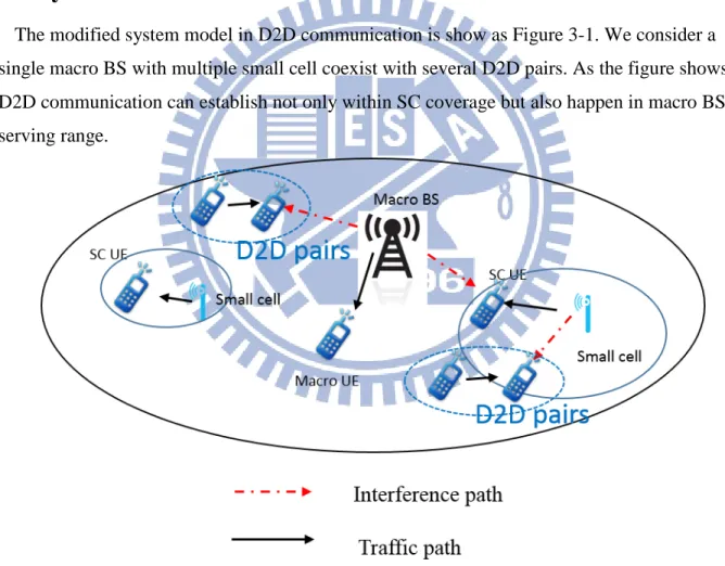
The modified system model in D2D communication is show as Figure 3-1. We consider a single macro BS with multiple small cell coexist with several D2D pairs. As the figure shows, D2D communication can establish not only within SC coverage but also happen in macro BS serving range.
Figure 3-1 System model for HetNet coexist D2D communication
In this system, we assume we have p SC, m macro BS, denote mode space S = �𝑛𝑛1, … , 𝑛𝑛𝑝𝑝 �, U pairs D2D UE, 𝐾𝐾𝑃𝑃 SC UE and 𝐾𝐾𝑀𝑀 macro UE, thus we have total UE = 𝐾𝐾𝑃𝑃+ 𝐾𝐾𝑀𝑀 + 2U. We can
represent Downlink SINR as below
𝑆𝑆𝑆𝑆𝑆𝑆𝑆𝑆𝑃𝑃𝑗𝑗 = 𝑃𝑃𝑃𝑃�ℎ𝑃𝑃𝑃𝑃𝑃𝑃� ∑𝑝𝑝𝑖𝑖=1,𝑖𝑖≠𝑃𝑃𝑛𝑛𝑖𝑖𝑃𝑃𝑃𝑃�ℎ𝑃𝑃𝑖𝑖𝑃𝑃�+∑𝑚𝑚𝑖𝑖=1𝑃𝑃𝑀𝑀�ℎ𝑀𝑀𝑖𝑖𝑃𝑃�+ ∑𝑈𝑈𝑖𝑖=1𝑃𝑃𝐷𝐷�ℎ𝐷𝐷𝑖𝑖𝑃𝑃�+ 𝑁𝑁0 , j ∈ 𝑆𝑆 ∀ 𝑗𝑗 ≤ 𝐾𝐾𝑃𝑃, q ∈ 𝑆𝑆 ∀ 𝑞𝑞 ≤ 𝑝𝑝 (4 - 1) 𝑆𝑆𝑆𝑆𝑆𝑆𝑆𝑆𝑀𝑀𝑗𝑗 = 𝑃𝑃𝑀𝑀�ℎ𝑀𝑀𝑃𝑃𝑃𝑃� ∑𝑝𝑝𝑖𝑖=1𝑛𝑛𝑖𝑖𝑃𝑃𝑃𝑃�ℎ𝑃𝑃𝑖𝑖𝑃𝑃�+∑𝑚𝑚𝑖𝑖=1,𝑖𝑖≠𝑃𝑃𝑃𝑃𝑀𝑀�ℎ𝑀𝑀𝑖𝑖𝑃𝑃�+ ∑𝑈𝑈𝑖𝑖=1𝑃𝑃𝐷𝐷�ℎ𝐷𝐷𝑖𝑖𝑃𝑃�+ 𝑁𝑁0 , j ∈ 𝑆𝑆 ∀ 𝑗𝑗 ≤𝐾𝐾𝑀𝑀, q ∈ 𝑆𝑆 ∀ 𝑞𝑞 ≤ 𝑚𝑚 (4 - 2) 𝑆𝑆𝑆𝑆𝑆𝑆𝑆𝑆𝐷𝐷𝑗𝑗 = 𝑃𝑃𝐷𝐷�ℎ𝐷𝐷𝑃𝑃𝑃𝑃� ∑𝑝𝑝𝑖𝑖=1𝑛𝑛𝑖𝑖𝑃𝑃𝑃𝑃�ℎ𝑃𝑃𝑖𝑖𝑃𝑃�+∑𝑚𝑚𝑖𝑖=1𝑃𝑃𝑀𝑀�ℎ𝑀𝑀𝑖𝑖𝑃𝑃�+ ∑𝑈𝑈𝑖𝑖=1,𝑖𝑖≠𝑃𝑃𝑃𝑃𝐷𝐷�ℎ𝐷𝐷𝑖𝑖𝑃𝑃�+ 𝑁𝑁0 , j ∈ 𝑆𝑆 ∀ 𝑗𝑗 ≤ 𝑈𝑈, q ∈ 𝑆𝑆 ∀ 𝑞𝑞 ≤ 𝑈𝑈 (4 - 3)
Where “P” denotes SC, “M” denotes macro BS and “D” denotes D2D UE pairs. 𝑃𝑃𝑃𝑃, 𝑃𝑃𝑀𝑀 and 𝑃𝑃𝐷𝐷 denote different nodes transmit power. ℎ𝑃𝑃𝑃𝑃𝑗𝑗, ℎ𝑀𝑀𝑃𝑃𝑗𝑗, ℎ𝐷𝐷𝑃𝑃𝑗𝑗 denote channel gain for desire signal ℎ𝑃𝑃𝑃𝑃𝑗𝑗, ℎ𝑀𝑀𝑃𝑃𝑗𝑗 and ℎ𝐷𝐷𝑃𝑃𝑗𝑗 denote channel gain for interference path, 𝑆𝑆0 denotes noise. Moreover,
con-sidering channel capacity, the achievable rate can rewrite as
𝐶𝐶𝑃𝑃𝑗𝑗 = 𝐵𝐵𝐵𝐵 𝑙𝑙𝑙𝑙𝑙𝑙2�1 + 𝑆𝑆𝑆𝑆𝑆𝑆𝑆𝑆𝑃𝑃𝑗𝑗� (4 - 4)
𝐶𝐶𝑀𝑀𝑗𝑗 = 𝐵𝐵𝐵𝐵 𝑙𝑙𝑙𝑙𝑙𝑙2�1 + 𝑆𝑆𝑆𝑆𝑆𝑆𝑆𝑆𝑀𝑀𝑗𝑗� (4 - 5)
𝐶𝐶𝐷𝐷𝑗𝑗 = 𝐵𝐵𝐵𝐵 𝑙𝑙𝑙𝑙𝑙𝑙2�1 + 𝑆𝑆𝑆𝑆𝑆𝑆𝑆𝑆𝐷𝐷𝑗𝑗� (4 - 6)
Where BW is system bandwidth. With the associate achievable rate, we can calculate system throughput with equation below
𝑇𝑇𝑠𝑠𝑠𝑠𝑠𝑠𝑠𝑠𝑠𝑠𝑠𝑠 = � 𝐶𝐶𝑃𝑃(𝑖𝑖) 𝐾𝐾𝑃𝑃 𝑃𝑃=1 + � 𝐶𝐶𝑀𝑀(𝑗𝑗) 𝐾𝐾𝑀𝑀 𝑗𝑗=1 + � 𝐶𝐶𝐷𝐷(𝑘𝑘) 𝑈𝑈 𝑘𝑘=1 (4 - 7)
3.2 Problem Formulation
Due to total UE 𝐾𝐾𝑃𝑃+ 𝐾𝐾𝑀𝑀 + 2U = constant and assume we have fix number of D2D pairs, if 𝐾𝐾𝑃𝑃 decrease, 𝐾𝐾𝑀𝑀 increase. Our comparison will based on finding
𝑚𝑚𝑚𝑚𝑚𝑚{ 𝑇𝑇𝑠𝑠𝑠𝑠𝑠𝑠𝑠𝑠𝑠𝑠𝑠𝑠} 𝑠𝑠𝑠𝑠𝑠𝑠𝑗𝑗𝑠𝑠𝑠𝑠𝑠𝑠 𝑠𝑠𝑙𝑙 1 ≤ 𝑖𝑖 ≤𝐾𝐾𝑃𝑃 1 ≤ 𝑗𝑗 ≤𝐾𝐾𝑀𝑀
1 ≤ 𝑘𝑘 ≤ 𝑈𝑈
(4 - 8)
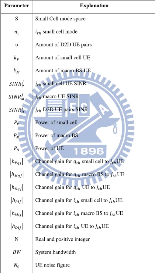
Table 4-1 is notation summary in this chapter.
Parameter Explanation
S Small Cell mode space 𝑛𝑛𝑃𝑃 𝑖𝑖𝑠𝑠ℎ small cell mode
u Amount of D2D UE pairs 𝑘𝑘𝑃𝑃 Amount of small cell UE
𝑘𝑘𝑀𝑀 Amount of macro BS UE
𝑆𝑆𝑆𝑆𝑆𝑆𝑆𝑆𝑃𝑃𝑗𝑗 𝑗𝑗𝑠𝑠ℎ small cell UE SINR
𝑆𝑆𝑆𝑆𝑆𝑆𝑆𝑆𝑀𝑀𝑗𝑗 𝑗𝑗𝑠𝑠ℎ macro UE SINR
𝑆𝑆𝑆𝑆𝑆𝑆𝑆𝑆𝐷𝐷𝑗𝑗 𝑗𝑗𝑠𝑠ℎ D2D UE pairs SINR
𝑃𝑃𝑃𝑃 Power of small cell
𝑃𝑃𝑀𝑀 Power of macro BS
𝑃𝑃𝐷𝐷 Power of UE
�ℎ𝑃𝑃𝑃𝑃𝑗𝑗� Channel gain for 𝑞𝑞𝑠𝑠ℎ small cell to 𝑗𝑗𝑠𝑠ℎUE
�ℎ𝑀𝑀𝑃𝑃𝑗𝑗� Channel gain for 𝑞𝑞𝑠𝑠ℎ macro BS to 𝑗𝑗𝑠𝑠ℎUE
�ℎ𝐷𝐷𝑃𝑃𝑗𝑗� Channel gain for 𝑞𝑞𝑠𝑠ℎ UE to 𝑗𝑗𝑠𝑠ℎUE
�ℎ𝑃𝑃𝑃𝑃𝑗𝑗� Channel gain for 𝑖𝑖𝑠𝑠ℎ small cell to 𝑗𝑗𝑠𝑠ℎUE
�ℎ𝑀𝑀𝑃𝑃𝑗𝑗� Channel gain for 𝑖𝑖𝑠𝑠ℎ macro BS to 𝑗𝑗𝑠𝑠ℎUE
�ℎ𝐷𝐷𝑃𝑃𝑗𝑗� Channel gain for 𝑖𝑖𝑠𝑠ℎ UE to 𝑗𝑗𝑠𝑠ℎUE
N Real and positive integer
BW System bandwidth 𝑆𝑆0 UE noise figure
𝐶𝐶𝑃𝑃𝑗𝑗 Capacity for small cell UE 𝐶𝐶𝑀𝑀𝑗𝑗 Capacity for macro UE 𝐶𝐶𝐷𝐷𝑗𝑗 Capacity for D2D UE 𝑇𝑇𝑠𝑠𝑠𝑠𝑠𝑠𝑠𝑠𝑠𝑠𝑠𝑠 System throughput
Table 3-1 Notation Summery
Chapter 4
I
SSUE
&
P
ROPOSED
S
OLUTION
In this chapter, we talk about the existing problem when D2D communication co-exist with densely deploy small networks, as we mentioned in previous chapter, small cell are deployed very close to each other and D2D UE will using same resource with small cell in order to en-hance bandwidth efficiency and throughput.
4.1 Issue & Proposed Solution I
4.1.1 Issue:Unnecessary Small Cell
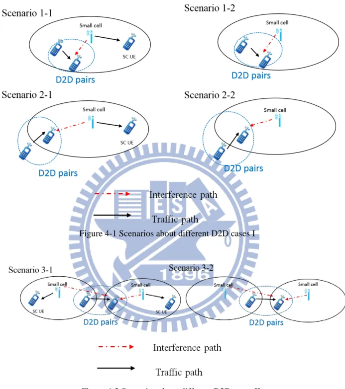
In dense urban areas, SC are deployed very close to each other and using same resource with D2D pairs to enhance bandwidth efficiency. When there is only single pair UE devices are within the small cell coverage and they start communicate each other. However, in current sys-tem, SC still need to turn on its radio radiation power in order to help macro BS no matter of-floading heavy traffic or else. Prior work [16] on mitigate interference for D2D focus on power allocation. But in some cases, turn off the SC can benefit system and straight forward. Figure 4-1 to Figure 4-2 shows several scenario.
Figure 4-1 Scenarios about different D2D cases I
Figure 4-2 Scenarios about different D2D cases II 4.1.2 Proposed Solution:D2D trigger small cell to sleep mode
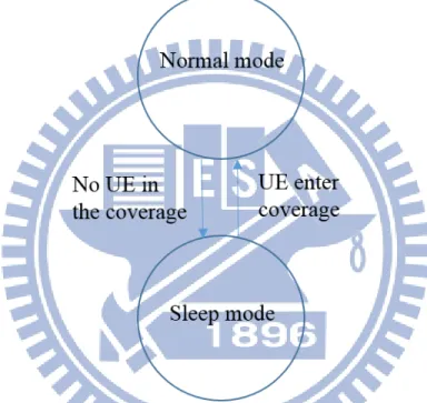
To solve the problem of unnecessary SC, we propose the Small Cell D2D State. It’s a control mechanism similar to small cell on/off or so call sleep mode see [3] and Figure 4-3. However, sleep mode control is depend on how many UE are close to SC. Our proposal is D2D UE would transmit a beacon before D2D communication establish. After SC or macro BS receive
beacon, if the SC is useless during D2D scenario, SC will turn off its radio radiation power. What kind of scenario is useless will briefly describe in Chapter 5. Figure 4-2 shows some common scenarios, first we can recognize some scenarios such as 1-2, 2-2 and 3-2 SC doesn’t have UE in the coverage instead of D2D pairs. It is obvious to realize that scenario 1-2, 2-2 and 3-2 SC should turn off its radio radiation power. However, 1-1, 2-1 and 3-1 are in different situ-ation, we will briefly descript system model and formulate problem in Chapter 3 and justify the result by simulation in Chapter 5. How SC switches mode is shown as Figure 4-4.
Figure 4-3 Example for small cell sleep mode
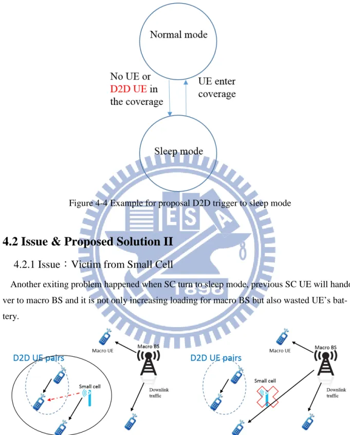
Figure 4-4 Example for proposal D2D trigger to sleep mode
4.2 Issue & Proposed Solution II
4.2.1 Issue:Victim from Small Cell
Another exiting problem happened when SC turn to sleep mode, previous SC UE will hando-ver to macro BS and it is not only increasing loading for macro BS but also wasted UE’s bat-tery.
(a) No D2D sleep mode small cell (b) With D2D sleep mode small cell
Figure 4-5 Example for victim appear after small cell turn off 4.2.2 Proposed Solution:Small Cell Grouping and Coordinate
However, in a densely deploy SC networks, SC are very close to each other and we can con-sider SC as TPs in CoMP technique. We can simply make SCs who is overlap to each other be-come several group, when there is a group member going to D2D sleep mode, UE in this SC will become victim, and victim could handover to other SC in same group furthermore we could add CoMP to enhance SC UE, detail is related to [7]. We simply make several SC who overlap to each other become a group. Figure 4-8 JT and SC grouping implement to enhance victim receive signal shows after SC turn off, victim handover to neighbor SC and CoMP add to SC group.
Figure 4-6 JT and SC grouping implement to enhance victim receive signal I
Figure 4-7 JT and SC grouping implement to enhance victim receive signal II
Figure 4-8 JT and SC grouping implement to enhance victim receive signal II
Chapter 5
S
YSTEM
L
EVEL
S
IMULATION AND
E
VALUATION
In this chapter, we will talk about simulation detail, parameter setting, usage environment and different condition performance evaluation and comparison. Section 5.1 talk about simulator building, different control mechanism and some assumption will be mentioned in section 5.1, 5.2 and 5.4. Comparison will show in last section 5.3 and section 5.3.
5.1 Simulator building – Initial Setting
5.1.1 Some assumption
Due to we are doing a system level simulation, we have some assumption as shown as below 1. System level simulation – No delay
2. TDD LTE – Explication in previous chapter.
3. Worst case – All UE are DL and UL at the same time.
4. Co-channel – Enhance bandwidth efficiency and throughput.
Some assumption is common in other research such as ignore delay and Doppler shift in low speed, and [17] suggest that in the simulation we can assume all UE devices are in the same up-link-downlink configuration.
5.1.2 Parameter setting
Parameter will follow 3GPP specification [5], standard some BS spec and transmit power and pathloss. D2D is standardize by [13], pathloss model suggest to use Winner + B1b [18] Table4-1.Additionally, we consider a single macro BS with multiple SC cellular network system, fol-lowing standard, our simulation are based on 10MHz bandwidth with 2GHz carrier, also we compare different amount of SC and UE. BS parameter is shown as Table 5-1.
Macro Pico UE
Tx power 46 dBm 24 dBm 23 dBm
Noise figure 5 dB 13 dB 9 dB
Radius 500 m 40 m N/A
Antenna gain 15 dBi 5 dBi 0 dBi
Table 5-1 Base station parameter
Pathloss between nodes is shown as Table 5-2. Pathloss case Macro – UE 𝑃𝑃𝑃𝑃𝐿𝐿𝐿𝐿𝐿𝐿(𝑆𝑆) = 30.8+24.2log10(𝑆𝑆) 𝑃𝑃𝑃𝑃𝑁𝑁𝐿𝐿𝐿𝐿𝐿𝐿(𝑆𝑆) = 2.7+42.8log10(𝑆𝑆) For 2GHz, R in m. Pico – UE 𝑃𝑃𝑃𝑃𝐿𝐿𝐿𝐿𝐿𝐿(𝑆𝑆) = 103.8+20.9log10(𝑆𝑆) 𝑃𝑃𝑃𝑃𝑁𝑁𝐿𝐿𝐿𝐿𝐿𝐿(𝑆𝑆) = 145.4+37.5log10(𝑆𝑆) For 2GHz, R in km
UE – UE 𝑃𝑃𝑃𝑃𝐿𝐿𝐿𝐿𝐿𝐿(𝑆𝑆) = 40.0log10(𝑆𝑆) + 7.56 – 17.3log10(ℎ′𝐵𝐵𝐿𝐿) – 17.3log10(ℎ′𝑀𝑀𝐿𝐿) + 2.7log10(𝑓𝑓𝑐𝑐)
𝑃𝑃𝑃𝑃𝑁𝑁𝐿𝐿𝐿𝐿𝐿𝐿(𝑆𝑆) = (44.9 - 6.55log10(ℎ𝐵𝐵𝐿𝐿)) log10(𝑑𝑑) + 5.83log10(ℎ𝐵𝐵𝐿𝐿) + 18.38
+ 23log10(fc) ( [18]Table 4-1) ℎBS = ℎMS = 1.5m, h′BS = h′MS = 0.8m
Table 5-2 Pathloss between nodes
Experiment parameter is shown as Table 5-3, Figure 5-1 to Figure 5-3 shows the distribution of every network.
Experiment parameter Value
Amount of UE 150, 180 Amount of pico 20, 25, 30 Amount of macro 1 UE velocity 3 km/hour System bandwidth (BW) 10 MHz Carrier frequency 2 GHz
System deployment Urban macro (500m)
UE drop Hotspot
Table 5-3 Experiment parameter
(a) 150 UE (b) 180 UE
Figure 5-1 Network deployment for 20 SCs
(a)150 UE (b) 180 UE
Figure 5-2 Network deployment for 25 SCs
(a)150 UE (b) 180 UE
Figure 5-3 Network deployment for 30 SCs
5.2 Mechanism Evaluation I
In Chapter 4, we have describe problem when D2D UE coexist with SC. For now, we are go-ing to choose which scenario should turn SC off. First scenario 1-2, 2-2 and 3-2 SC should in-clude to D2D state, turn off its radio radiation power. For scenario 3-1 we can simply consider this case as two different scenario 2-1 SC. Remain scenarios is shown as Figure 5-4.
Figure 5-4 Remain scenarios
Supposedly, include scenario 1-1 SC to D2D state can get better performance than scenario 2-1 since D2D UE in scenario 1-1 is much closer to SC than other scenarios. As a result, we conclude several method by closing different scenario and it is shown as Table 5-4. Section 5.3 will show comparison about every method in different experiment environment.
Method Detail
Method 1 Sleep mode only
Method 2 1-1,1-2, 2-2
Method 3 2-1,1-2, 2-2
Method 4 1-1, 2-1,1-2, 2-2
Table 5-4 Method description detail I
5.3 Simulation Result I
In simulation I, we consider whether SC have D2D sleep mode or not, from the result we can also observe sometimes turn off all the SC is not a bad choose but it will not be the best solu-tion. Figure 5-5 to Figure 5-16shows DL SINR and system DL throughput also compare in dif-ferent experiment environment. We can recognize that the increasing amount of SC will effects the control method, with higher amount of SC will get more significant performance. Amount of UE effects not only throughput but also effects difference between methods to methods. It is because effect form SC will be obstruct by the increasing of UE amounts. We analysis different experiment environment and compare together, result is shown as figure below, and it conform to our assumption. Main SINR comparison refer to Table 5-5 SINR comparison I and using percentage to show how much better than method 1.
Figure 5-5 20 SC and 150 UE DL SINR
Figure 5-6 20 SC and 150 UE DL throughput
Figure 5-7 25 SC and 150 UE DL SINR
Figure 5-8 25 SC and 150 UE DL throughput
Figure 5-9 30 SC and 150 UE DL SINR
Figure 5-10 30 SC and 150 UE DL throughput
Figure 5-11 20 SC and 180 UE DL SINR
Figure 5-12 20 SC and 180 UE DL throughput
Figure 5-13 25 SC and 180 UE DL SINR
Figure 5-14 25 SC and 180 UE DL throughput
Figure 5-15 30 SC and 180 UE DL SINR
Figure 5-16 30 SC and 180 UE DL throughput
M1 M2 M3 M4 20SC 150UE 4.72% 2.98% 2.54% 25SC 150UE 19.67% 19.24% 18.55% 30SC 150UE 24.10% 23.24% 22.45% 20SC 180UE 12.76% 12.07% 11.62% 25SC 180UE 10.0% 8.08% 5.52% 30SC 180UE 4.65% 4.38% 4.09% Table 5-5 SINR comparison I
From Table 5-5 we can observate that SC can work well with D2D on/off state and always better than method 1 and from the result we can sort the performance from high to low is M2>M3>M4. It is because scenario 1-1 D2D devices are both within SC coverage and scenario 2-1 D2D devices are located at SC edge. M4 close both scenario 1-1, 2-1 and it brings more victim than M2, M3. In 30 SC 150 UE case, D2D on/ off control has best performance. In 25 SC 150 UE and 20 SC 180 UE M2 to M4 all have 10% better than M1. M2 win M4 the most at 25 SC 180 UE case.
5.4 Mechanism Evaluation II
Following chapter 3 propose solution II, adding SC coordinate transmission in mechanism evaluation I method detail shown as Table 5-6 and result will show in section 5.5. In the simu-lation, JT is related to amount of transmitter and receiver. Every UE devices can use full system bandwidth 𝐵𝐵𝐵𝐵 since we consider a co-channel cellular network, so even we consider CoMP bandwidth can still be fully utilized.
Method Detail
Method 1-1 Sleep mode only
Method 1-2 Same as Method 1-1 and consider CoMP
Method 2-1 1-1,1-2, 2-2
Method 2-2 Same as Method 2-1 and consider CoMP
Method 3-1 2-1,1-2, 2-2
Method 3-2 Same as Method 3-1 and consider CoMP
Method 4-1 1-1, 2-1,1-2, 2-2
Method 4-2 Same as Method 4-1 and consider CoMP
Table 5-6 Method description detail II
5.5 Simulation Result II
Supposedly, consider CoMP should benefit system but the result is not always significant. In the simulation we can observe the amount of SC affects CoMP performance. Figure 5-17 to Figure 5-22 shows DL SINR, throughput and compare to original on/off method. We can see the result from simulation that with amount of SC increase, performance from JT CoMP will become weaker but still get benefit from CoMP in some scenario. In method 4-2, can get better improvement than method 2-2 and method 3-2 since number of victim in method 4-1 is more than method 2-2 and 3-2. However, method 2-2 and method 3-2 still have higher performance than method 4-2 since closing too many SC and without any control still get the worst perfor-mance in our simulation result. Main SINR comparison refer to Table 5-7 and using percentage to show how much better than method 1-1.
Figure 5-17 20 SC and 150 UE DL throughput
Figure 5-18 25 SC and 150 UE DL throughput
Figure 5-19 30 SC and 150 UE DL throughput
Figure 5-20 20 SC and 180 UE DL throughput
Figure 5-21 25 SC and 180 UE DL throughput
Figure 5-22 30 SC and 180 UE DL throughput
M1-1 M1-2 M2-1 M2-2 M3-1 M3-2 M4-1 M4-2 20SC 150UE 0.11% 4.72% 5.20% 2.98% 4.83% 2.54% 4.60% 25SC 150UE 0.20% 19.67% 20.22% 19.24% 20.0% 18.55% 19.44% 30SC 150UE 0.27% 24.1% 24.64% 23.24% 24.47% 22.45% 23.99% 20SC 180UE 0.16% 12.76% 13.21% 12.07% 13.04% 11.62% 12.85% 25SC 180UE 0.44% 10.0% 10.50% 8.08% 9.86% 5.52% 8.45% 30SC 180UE 0.86% 4.65% 5.09% 4.38% 4.99% 4.09% 4.94%
Table 5-7 SINR comparison II
From Table 5-7, M1-1, M2-1, M3-1 and M4-1 is same as Table 5-5 M1, M2, M3 and M4. M1-2, M2-2, M3-2 and M4-2 are results about CoMP add to M1-1, M2-1, M3-1 and M4-1. In M4-1 and M4-2, numbers of victim is more than other method. As a result, M4-2 will have better performance than M4-1 and more significant than other method in all of the experiment parameter. Gain in M2-2 and M3-2 is not significant, it is because the victim number is less than M4-2. And in some situation we have target to achieve, for example, assume we need 5 % better performance than M1, we can consider M2-2 in our system. CoMP performance is not as significant as usual since the environment is different. Traditionally, CoMP has 9% to 10% enhancement in TDD LTE but situation is different in ultra-dense SC networks. Transmitters are ubiqueious and signal sources are near each other. Therefore, after D2D state add in CoMP can be improved and more suitable in this situation.
Chapter 6
C
ONCLUSION
In this thesis, we consider a novel on/off SC control mechanism depends on D2D transmis-sion, D2D communication is very popular in various 3GPP group, companies propose a lot of documents and protocol. Moreover, D2D has been include to Release 12 and related conference is still holding. In our research, we focus on interference problem and solve by our proposal “SC D2D sleep mode” also we solve victim problem by coordinate SC transmission “CoMP”, came from previous research and studies.
For interference-limited system, interference management is always an important event, we analysis various D2D scenarios and chose whether the scenario should turn off SC to mitigate interference. Some obvious scenarios we should always turn off SC, SC with single pair D2D device scenarios is not difficult to recognize, but current small cell networks appears earlier than in band D2D so it has not been consider before. As a result, Chapter 3 provide a combina-tion formula about D2D communicacombina-tion with small cell on/off control mechanism, therefore we can verify two kind of mechanism mix together and simulation in Chapter 5. Following 3GPP contribution and their document, we built a LTE simulator and adding D2D devices in our ex-periment.
D2D proposed to solve network loading, so we select an extreme environment, co-channel and every UE are transmitting data at the same time. In the simulation we can recognize that with increasing amount of SC the more interference we get. As a result, control SC wake up or not will become a more important in a densely deploy SC network.
In issue 2, we select CoMP to handle victim since the research about CoMP is almost ubiqui-tous and well known. Performance about CoMP has been evaluated, with the increasing of vic-tim the performance become more significant. In method 1-1 and 1-2, throughput enhance from CoMP is the worst in whole research, it is because method 1-1 and 1-2 did not make any inter-ference management also these two method have least victim. Method 4-1 and 4-2 have largest victim, however, without good management can’t get highest performance.
Basically, on/off control is an extreme power control mechanism, so future work can further consider SC DL power control implement in coexist D2D networks. Different power control algorithm may provide different performance or enhancement but 3GPP has discuss DL power
control in current conference, and detail algorithm hasn’t been done yet. Therefore, in such an extreme environment we still suggest on/off control and we can handle victim UE by CoMP. Still, we need another algorithm support channel allocation.
Reference
[1] Xingqin Lin, Jeffrey G.Andrews, "An overview on 3GPP Device-to-device Proximity ser-vices", Sep. 2013.
[2] Ying Peng, Qiubin Gao, Shaohui Sun, Zheng Yan-Xiu, "Discovery of Device-Device Proximity", 2013.
[3] Sung-Guk Yoon, Jonghun Han, Saewoong Bahk, "Low-duty Mode Operation of Femto Base Stations in a Densely Deployed Network Environment", 2012.
[4] Bhaskar Gupta, Anil Kumar Singh, "LTE Advanced: Carrier Aggregation Deployments",
International Journal of Engineering sciences & Research Technology, pp. 807-810, April
2013.
[5] 3GPP TR 36.828 v11.0.0, "Further enhancements to LTE Time Division Duplex", June 20 12.
[6] Mamoru Sawahashi, Yoshihisa Kishiyama, Akihito Morimoto, Daisuke Nishikawa, Mo-tohiro Tanno, "Coordinated Multipoint Transmission/Reception Techniques for LTE-Advanced", IEEE Wireless Communication, pp. 26-34, June 2010.
[7] 3GPP TR 36.819 v11.1.0, "Coordinated multi-point operation for LTE physical layer as-pects", December 2011.
[8] Shaohui Sun, Qiubin Gao, Ying Peng, Yingmin Wang, "Interference Management Through CoMP in 3GPP LTE-Advanced Networks", IEEE Wireless Communication, pp. 59-66, Feb. 2013.
[9] Young-Han Nam, Lingjia Liu, Jianzhong (Charlie) Zhang, "Cooperative communication for LTE-advanced – relay and CoMP", International Journal of Communication Systems, pp. 5610-5613, 2012.
[10] S. Annapureddy et al., "Coordinated Joint Transmission in WWAN", IEEE
Communica-tion Theory workshop, May 2010.
[11] Alexander Pyattaev, Kerstin Johnsson, Sergey Andreev, Yevgeni Koucheryavy, "3GPP LTE traffic Offloading onto WiFi Direct", IEEE WCNC Workshop on Mobile Internet:
Traffic Modeling, Subscriber Perception Analysis and Traffic-aware Network Design, pp.
135-140, 2013.
[12] Ying Peng, Qiubin Gao, Shaohui Sun, Zheng Yan-Xiu, "Discovery of Device-Device Proximity", First International Workshop on Device-to-Device Communication and
Net-works (D2D 2013), pp. 176-181, 2013.
[13] 3GPP TR 36.843 v12.0.1, "Study on LTE Device to Device Proximity Services", March 2014.
[14] 3GPP TR 22.803 v12.2.0, "Feasibility study for Proximity Services (ProSe)", June 2013. [15] 3GPP TS 22.278 v13.0.0, "Service requirements for the Evolved Packet System (EPS)",
June, 2014.
[16] Yinuo He, Xi Luan, Jiajia Wang, Mei ping Feng, Jianjun Wu, "Power Allocation for D2D Communications in Heterogeneous Networks", ICACT 2014, pp. 1041-1044, February 16 2014.
[17] 3GPP TS 136.211 v10.0.0, "Physical channels and modulation", January 2011. [18] D5.3: WINNER+ Final Channel Models, available at
http://www.projects.celtic-initia-tive.org/winner%2B/WINNER+%20Deliverables/D5.3_v1.0.pdf.