行政院國家科學委員會專題研究計畫 成果報告
總計畫:EHOME : 電子家庭雛型之設計與實作
計畫類別: 整合型計畫 計畫編號: NSC91-2218-E-002-009- 執行期間: 91 年 08 月 01 日至 92 年 07 月 31 日 執行單位: 國立臺灣大學資訊工程學系暨研究所 計畫主持人: 陳俊良 報告類型: 完整報告 處理方式: 本計畫可公開查詢中 華 民 國 93 年 2 月 20 日
行政院國家科學委員會補助專題研究計畫成果報告
eHome:電子家庭雛型之設計與實作總計畫 (3/3)
計畫類別:整合型計畫
計畫編號:NSC 91-2218-E-002-009-
執行期間:91 年 08 月 01 日至 92 年 07 月 31 日
計畫主持人:陳俊良
共同主持人:許清琦、鄭士康、王勝德
計畫參與人員:
成果報告類型(依經費核定清單規定繳交):完整報告
本成果報告包括以下應繳交之附件:
□赴國外出差或研習心得報告一份
□赴大陸地區出差或研習心得報告一份
□出席國際學術會議心得報告及發表之論文各一份
□國際合作研究計畫國外研究報告書一份
處理方式:除產學合作研究計畫、提升產業技術及人才培育研究計畫、
列管計畫及下列情形者外,得立即公開查詢
□涉及專利或其他智慧財產權,□一年□二年後可公開查詢
執行單位:國立台灣大學資訊工程學系
中 華 民 國 92 年 12 月 31 日
中文摘要
隨著半導體相關技術顯著的成長與網際網路的盛行,愈來愈多的家庭網路系統標 準與家庭網路介面標準被發展出來。這些標準依照開放性可分為國際標準,公開 標準與私有/私人標準三大類。除此之外,近年來可攜式裝置,如手機與 PDA, 有逐漸深入每個人家庭生活的的趨勢。其已成為未來家庭網路應用中重要的終端 應用平台。 本篇論文著重於如何設計出一個新的家庭網路系統 – eHome system,其能 整合所有的家庭網路標準並且提供與可攜式裝置相互連結的機制來實現遠端存 取的能力。也就是說說,我們希望能夠建構出一個泛用型家庭網路系統,且希望 能夠透過可攜式裝置,在家或在外都能控制家中的任一家電。 目前已經成功地實做出 eHome 家庭網路系統雛形,當我們在外的時候,可 以使用內建 WAP 瀏覽器的 PDA 或是手機,經由 GSM/GPRS 無線網路連上 Internet,再進一步利用 HTTP 協定,連上家中伺服器來控制家中的任一家電。 在家時,則可以直接透過 PDA 上的友善人機介面,經由藍芽無線傳輸來遙控家 中電器,讓使用者無論在任何地方皆能掌握家中一切狀況。Abstract
The semiconductor technology has extremely advanced and Internet is now in widespread usage. As a result, more and more international, open and proprietary home network standards (home systems and network interfaces) are evolved recently. Moreover, the portable device then becomes the popular and important appliance.
This report aims to propose a new home system, which integrates with complete home network standards, and the portable devices for providing capability of remote access. Moreover, we have implemented a tentative prototyping with low cost. Now we can use the mobile phone or PDA built in WAP browser to control the home appliances remotely through Internet and HTTP protocol outside home. Moreover, we can control the home appliances directly via friendly control user interface and BlueTooth inside home without any GSM/GPRS service charge
Table of Contents
Chapter 1. Introduction ...1
1.1 Trend ...1
1.2 eHome System ...2
1.3 Report outline...4
Chapter 2. Home Network Interface Standards ...5
2.1 Overview...5 2.2 Wired Technologies...6 2.2.1 Ethernet ...6 2.2.2 HomePNA...7 2.2.3 HomePlug ...9 2.2.4 HomeCNA ...10 2.2.5 IEEE 1394 ...12 2.2.6 USB...13 2.2.7 RS-232 ...14 2.3 Wireless Technologies...15 2.3.1 Wireless LAN - 802.11 ...15 2.3.2 BlueTooth...16 2.3.3 HomeRF...19
Chapter 3. Home System Standards...21
3.2 OSGi ...22 3.2.1 History...22 3.2.2 Overview...23 3.2.3 Feature...23 3.2.4 Architecture...24 3.2.5 Related reaches ...28 3.3 HES ...30 3.3.1 History...30 3.3.2 Overview...30 3.3.3 Components ...31 3.4 HAVi ...32 3.4.1 History...32 3.4.2 Overview...33 3.5 Jini...35 3.5.1 History...35 3.5.2 Overview...35 3.6 UPnP ...36 3.6.1 History...36 3.6.2 Overview...36 3.7 X10...37 3.7.1 History...37 3.7.2 X10 Protocol ...38 3.8 Others ...39
Chapter 4. eHome System...40
4.1 Introduction...40
4.2.1 VSG Based Home System ...41
4.2.2 Virtual Overlay Network...43
4.3 Design Considerations ...45
4.3.1 Multiple Home Systems and Interfaces ...45
4.3.2 Web services ...46
4.3.3 Portable devices ...46
4.3.4 eHome System Protocol...47
4.3.5 High Flexibility, Scalability and Low Cost...47
4.4 System Architecture ...48
4.5 System Components...50
4.5.1 eHome Residential Gateway...50
4.5.2 eHome Gateway...52
4.5.3 eHome Room Center...57
4.6 eHome Protocol ...64 Chapter 5. Implementation...65 5.1 Introduction...65 5.2 System Components...66 5.2.1 eHome Server...66 5.2.2 eHome IA...70
5.2.3 eHome Room Center...78
5.3 X10 Home Network ...79
5.4 Integration ...80
5.4.1 eHome System Prototyping ...80
5.4.2 Ultimate Mobile Phone Prototype ...81
Chapter 6. Conclusion...83
6.2 Future Work ...84 References...86
Table of Figures
Figure 1.1: eHome System Architecture ...2
Figure 2.1: Network Access Technologies...5
Figure 2.2: HomePNA Networking Topology ...7
Figure 2.3: HomePNA Data Frame Format ...8
Figure 2.4: HomePlug Networking Topology...9
Figure 2.5: HomeCNA Networking Topology...10
Figure 2.6: HomeCNA : Five Networks – one cable ... 11
Figure 2.7: USB Network Topology ...13
Figure 2.8: RS-232 data frame format ...15
Figure 2.9: BlueTooth Scatter net Network Topology ...17
Figure 2.10: BlueTooth Protocol Stack...18
Figure 3.1: Home systems choice in 2002 ...22
Figure 3.2: OSGi Gateway...23
Figure 3.3: OSGi End-to-End Architecture ...24
Figure 3.4: OSGi Framework Architecture...26
Figure 3.5: Appliances connect to Home Electronic System...31
Figure 3.6: An example of HomeGate implementation ...32
Figure 3.7: HAVi Architecture ...33
Figure 3.8: Jini Architecture ...35
Figure 3.10: Waveform of binary data using X10 PLC ...38
Figure 3.11: Basic X10 Message Format...38
Figure 3.12: The Waveform of X10 “Start Code” ...39
Figure 4.1: eHome Home System Architecture ...40
Figure 4.2: Overview of VSG based Framework ...42
Figure 4.3: Prototype of VSG based Framework Implementation ...43
Figure 4.4: The Architecture of Virtual Overlay Network...43
Figure 4.5: Prototype of VSG based Framework Implementation ...44
Figure 4.6: Architecture of eHome Residential Gateway ...50
Figure 4.7: eHome Gateway Category...52
Figure 4.8: Architecture of Protocol Gateway ...52
Figure 4.9: Architecture of Control-Message Gateway ...54
Figure 4.10: Request/Response and Notification/Event Diagram ...54
Figure 4.11: Architecture of Medium Gateway ...56
Figure 4.12: eHome System Architecture with eHome Room Center...57
Figure 4.13: Service Proxy – Service Registry...59
Figure 4.14: Service Proxy – Service Discovery/Access...60
Figure 4.15: eURC Proxy – Service Discovery ...62
Figure 4.16: eURC Proxy – Service Access ...63
Figure 5.1: eHome Server Architecture ...66
Figure 5.2: Flow chart of HTTP request processing of WML Server...70
Figure 5.3: RS-232 IA Hardware Function Block ...72
Figure 5.4: RS-232 IA Software Architecture...72
Figure 5.5: BlueTooth Simple IA HW Function Block ...74
Figure 5.6: BlueTooth IA Software Architecture ...75
Figure 5.8: IR Wizard IA System Architecture ...77
Figure 5.9: BlueURC IA System Architecture...78
Figure 5.10: eRC Prototyping System Architecture ...78
Figure 5.11 X10 Subsystem Integration ...79
Figure 5.12 Overall Architecture of eHome system prototyping...80
Figure 5.13: Ultimate Mobile Phone Architecture...81
List of Tables
Table 2.1: Ethernet Physical Layer Media Specifications ...6 Table 3.1: OSGi Related Projects ...29
Chapter 1.
Introduction
1.1 Trend
The rapid growth of Internet and semiconductor technology has accelerated the coming of the Post-PC (Personal Computer) century. The Post-PC century is an emerging term because there are more and more consumer electronics becoming more intelligent due to falling costs and increased capability of today’s microprocessors. The consumer electronics no more comprises a hardware-only domain, and they are both hardware and software solutions to deliver digital entertainment.
One emerging type of the consumer electronics, IA (also named Internet Appliance, Information Appliance, or Intelligence Appliance), usually has Internet capability and shares the information with each other. Moreover, more and more consumer electronics are linked by network and can be further connect to Internet in the future. The applications of IA are various especially in the field of home networking. Home networking is a popular topic will expand huge market in the future. Some marketing surveys of home networking are shown in the following lists:
According to HAA (Home Automation Association, http://www.homeautomation.org) market survey. Demand for home automation will grow 20% every year.
IDC (http://www.idcresearch.com/) and In-Stat (www.in-stat.com) the sales volume of digital home products would exceed PC by 2003. The sales volume of digital home products will be 10 times of PC by 2010, and the
global market will become a $580 billion industry when 0.9 billion families use digital equipment.
Yankee (Yankee Group, http://www.yankeegroup.com) predicted. There will be 12.4 million of US homes use home networking equipment in 2002. Above market surveys are extracted from. [1]
Furthermore, there are some reasons to accelerate growing of home networking [2][3][4]. The reasons are listed as follows:
Rise in Workspace changed to Small Office and Home Office. Multi-PCs (Personal Computers) in Homes.
More and More consumer electronics will link together by network such as multiple PCs, printers, and other IAs.
Sharing a broadband Internet access.
Sharing content include multimedia and data among IAs. People want to access the Internet in different room.
1.2 eHome System
Figure 1.1: eHome System Architecture
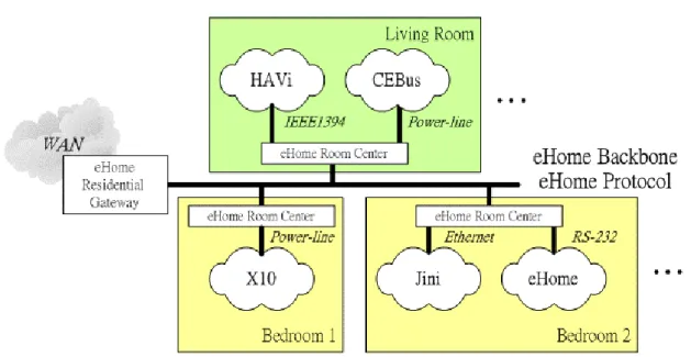
According to the trend of home networking, we known that there are different multiple home networking systems and interface coexisting in future home. Therefore, it is urgent demand for designing a home system that can integrate with whole home networking systems and interfaces. Besides, it is very important that to integrates with
the portable devices to provide the capability of remote access in the local home network.
We propose a general home system named eHome. It is low-cost, easy to use and construct, highly flexible, and downward compatible. Furthermore, it integrates with the portable devices. Figure 1.1 illustrates the architecture of eHome system. We can see that eHome system is a gateway-based architecture to intend to integrate existing home network system standards such as HAVi, and proprietary home system but popular such as X10. There is only one eHome Room Center that plays the role of central control in each room. Every eHome Room Center has three main components: eHome Gateway, eURC Proxy, which integrates with portable to provide capability of remote access and Service Proxy which manages the services of the local home network. Besides, eHome Room Center will connect its local home systems into eHome backbone finally. Accordingly, the home systems will be connected all together and can cooperate with each other through eHome Room Center. The protocol called eHome protocol running over eHome backbone can be any protocol, such as HTTP, SOAP, etc., depended on the demand. Therefore, choosing what protocol as eHome protocol will cause some issues and the capabilities of eHome system. For instance, if you chose only HTTP as eHome protocol, then you will need to use the URL-based naming to identify each home appliance and eHome system will not be capable of the multimedia streaming.
EHome Gateway is specifically classified into three categories: Protocol Gateway, Control-Message Gateway, and Medium Gateway. The Protocol Gateway is responsible for the interoperability among eHome system and the home network system standards, which have the characteristics such as service discovery, proprietary network protocol. The Control-Message Gateway is dedicated for message conversion between two message based home network systems such as X10 and eHome. Medium Gateway, however, only take charge of conversing the message/data between the different network interfaces such Ethernet to RS-232 without any modification.
We also implement a prototype to verify the integrity. This prototype has integrated many technologies such as Java, BlueTooth, TCP/IP, GSM/GPRS, RS-232, ASK-RF, Embedded system etc. Moreover, we define a new control protocol as our eHome protocol in our implementing prototype. This protocol is easy to implement and is low data transferring overhead. We can use this control protocol to control all
appliances such as turning on lamp, turning on TV, etc. in eHome system. Moreover, you can access the home service such as Lamp ON/OFF by WAP Browser built in portable device through GSM/GPRS wireless network outside the house. And you can also use the friendly user interface of the portable device to access the home service through BlueTooth directly without any GSM/GPRS service charge.
1.3 Report outline
We have introduced the trend of home networking nowadays and propose new home network system architecture - eHome. In the remaining chapters, we will give more details about home network technologies, eHome system and our implemented eHome prototype.
There are many technologies in the home network area. Generally, we can divide the technologies into two major parts: the home network interface standards and the home network system standards, or called middleware. Besides, they home network interface standards can be further classified into wired and wireless technologies which will be discussed in Chapter 2.
The home network system standard is a system architecture, which may comprise both hardware and software or only software framework, and in which the devices connected by the network can cooperate and discover services among devices. Some of the home network standards such as HAVi, Jini, OSGi, UPnP, etc. We will introduce in Chapter 3.
Chapter 4, then, will give you an overview of eHome system. We will point out the consideration in designing eHome system and introduce every major component of eHome system. These components are intended to solve some issues of integration of different home networking systems. Besides, in Chapter 5, the implementation of eHome system will be discussed. We will introduce each component of implementation prototype of eHome system and point out our consideration in designing.
Finally, in Chapter 6, we will address some future works and problems which should be improved and modified in our proposed eHome system and implemented prototype.
Chapter 2.
Home Network
Interface Standards
2.1 Overview
Figure 2.1: Network Access Technologies
Figure 2.1 gives us an overview of network access technologies. These technologies can be separated into two major categories: WAN (Wide Access Network) and HAN (Home Network Access). Many standards belong to HAN; for instance, Ethernet [7] and HomePNA [12], and they can be further categorized according to wired or wireless technologies. We will introduce some important standards and point out their
main features. Besides, we will analyze their disadvantages and advantages.
2.2 Wired Technologies
2.2.1 Ethernet
Ethernet technology is based on IEEE (Institute of Electrical and Electronic Engineers) 802.3 standard [7], which has many revisions because of its interoperability between many manufactures. And the original developer are DEC, Inter and Xerox. The wire structure can be twisted pair, coaxial cable, fiber etc. They are bi-directional, typically are strongly reliable, and thus they are popularly used as the standard choice for PCs and printers. Currently its speed is up to 10 Mbps. The new version called Fast Ethernet support data transfer rates of 100 Mbps. And the next new version, Gigabit Ethernet, will support data transfer rates of 1 Gbps.
Ethernet standard defines two layers of the OSI Reference Model. One is a physical layer, and the other is a link layer. The PHY (Physical layer) is dedicated for how to transmit unstructured raw data over a physical medium, and it also describes the electrical, mechanical, and functional interface to the network. There are many media specifications used for supporting different data rates, media, and topology configurations. Following Table 2.1 will show some common media specifications.
Max. Cable Length Standard IEEE Speed Medium Topology
Half Duplex Full Duplex 10Base5 802.3 10 Mb/s Single 50-ohm RG-58 coaxial
cable (thin Ethernet
Bus 500 M N/A 10Base-T 802.3i 10 Mb/s Two pairs of 100-ohm
Category 3 or better UTP cable
Star 100M 100M
10Base-FL 802.3i 10 Mb/s Two Optical Fibers Start 2000M >= 2000M 100Base-TX 802.3u 100 Mb/s Two pairs of 100-ohm
Category 5 UTP cable
Star 100M 100M
1000Base-TX 802.3ab 1Gb/s Four pair of 100-ohm Category 5 or better cable
Star 100M 100M
Table 2.1: Ethernet Physical Layer Media Specifications
The data link layer is focus on how to get data packets in the network. It can be divided to two sub-layers LLC (Logical Link Control) and MAC (Medium Access Control). The LLC is the upper sub-layer in data link layer to support error checking. And the lower sub-layer MAC is focus on how to get data packet in the network. The
CSMA/CD technique used in Ethernet and Fast Ethernet MAC layer is very important protocol for the later MAC layer development
The CSMA/CD is the abbreviation of Carrier Sense Multiple Access/Collision Detection. There is an interesting metaphor, “The CSMA/CD is a protocol functions like a dinner party in a dark room. Everyone around the table must listen for a period of silence before speaking (Carrier Sense). Once a space occurs everyone has an equal chance to say something (Multiple Access). If two persons start talking at the same instant they detect that fact, and quit speaking (Collision Detection.)”. [9] We map it to Ethernet operation. First when one interface is transmitting data, there will be a signal on the channel called “carrier”. One interface needs to sense signal on the channel before sending the data out. This process is called “Carrier Sense”. Secondly, the priority of all Ethernet interfaces is the same. And we call it “Multiple Access”. It is possible that two interfaces sense no carrier to send data out simultaneously because every interface has the same priority and the signals take the finite time to travel one end of Ethernet to the other. We call this situation “Collision”. There is one way to solve this problem. When MAC senses the collision signal, it will stop current transmission and resend after back-off time.
2.2.2 HomePNA
2.2.2.1 History
HomePNA (Home Phone-line Networking Alliance) [12], an organization founded in June 1998, is dedicated to the development of standards and specifications for interoperable, home-networked devices that use existing twisted pair phone wire. It was founded in June 1998. The major members of HomePNA currently are .2Wire, 3COM, Agere System, AMD, AT&T Wireless, Broadcom, Compaq, Conexant, CopperGate Communications, HP, Motorola, IBM, Inter etc.
2.2.2.2 Overview
HomePNA standard comprise physical layer and data link layer mapped to OSI reference model. It also defines the MAC (Media Access Control) layer which uses the CSMA/CD as same as the 802.3 Ethernet Standard. And refer to Figure 2.3 the data of upper layer is compatible with frame type in 802.3 Ethernet data frame type. So the application based on Ethernet can be reused in HomePNA too.
Figure 2.3: HomePNA Data Frame Format [8]
The bandwidth of HomePNA v1.1 is up to 1Mbps in the symmetric mode within distance up to 500ft. HomePNA v2.0 extends the distance to 1000ft. and the speed to 10Mbps. Moreover, the speed is further extended to 100Mbps in HomePNA v3.0 Standard. And HomePNA v3.0 will support the voice-over-HomePNA extend from HomePNA v2.0 by enabling eight simultaneous high-quality voice stream within home. Moreover HomePNA v3.0 can coexist with other services such as ADSL, ISDN and POTS, fully downward compatible with HomePNA v2.0, and support the QoS (Quality of Service) for transmitting data to end-user reliably.
Because HomePNA takes advantages of the existed phone-line used by some technologies such as ADSL, it needs the frequency division multiplex technology to
carry different analog signal on the same phone-line. The analog telephony services use the low part of spectrum: below 35kHZ. ADSL uses spectrum up to 1.1 MHz. However, HomePNA selected 4 to 10 MHz as its spectrum. HomePNA v1.1 utilizes the PPM and HomePNA v2.0 uses QAM (Quadrature Amplitude Modulation) modulation technologies separately to get more throughputs and to achieve greater robustness. To obtain more details, please refer to [8][10][11][12].
2.2.3 HomePlug
Figure 2.4: HomePlug Networking Topology
2.2.3.1 History
There are many technologies intended to carry the digital data on the existed power line such CEBus, Lonworks, X10 etc. Figure 2.4 is the illustration of power-line network structure of HomePNA. HomePlug [13] Power-line Alliance, established in 2000 is the organization emphasizing on standardization of in-home power-line network. There are 13 founding members include 3COM, AMD, Cisco, Systems, Compaq, Conexant, Enikia, Intel, Intellon, Motorola, Panasonic, Radio, Shack, SONICblue, and Texas Instruments. HomePlug has chosen the Intellon power-line technology as its baseline in the first-generation specification.
2.2.3.2 Overview
HomePlug has defined a robust PHY layer and an efficient MAC layer in order to make a reliable communication on the power-line medium. The PHY is focus on the modulation, coding, and basic packer formats. And the MAC is used to control the sharing of the medium among multiple clients.
The OFDM (Orthogonal Frequency Division Multiplexing) widely used in the DSL and terrestrial wireless distribution of television signals is used as the basic transmission technique in the PHY. HomePlug use ODDM in the robust mode rather than in the continuous mode. HomePlug uses concatenated Viterbi and Reed Solomon forward error correction with interleaving for payload data, and TPC (Turbo Product Coding) for sensitive frame control data fields.
HomPlug also utilizes the variant of well-known CSMA/CD technique protocol as the MAC layer protocol. Several features have been added to support priority classes, provide fairness, and allow the control of latency. The MAC also added the 56-bit DES (Data Encryption Standard) to provide the security of data transmission. It is probably announced by Intellon Corp that the data rate of HomePlug currently is up to 14 Mbps and 100 Mbps in [15]. HomePlug has released HomePlue 1.0 specification in June 2001. And the next generation HomePlug Specification will support distributions of data and multi-stream entertainment including High Definition television (HDTV) and Standard Definition television (SDTV) throughout the home. More details about HomePlug, please see the references [13][14][15][16].
2.2.4 HomeCNA
2.2.4.1 History
HomeCNA (Home Cable Network Alliance) [17] is established in April 2001. “HomeCNA Vision: Leverage the preponderance of coaxial wire in the home as the networking medium for entertainment, voice and data distribution in the connected home” described in HomeCNA Alliance presentation [18]. Figure 2.5 is the brief of HomeCNA Networking topology.
2.2.4.2 Overview
Figure 2.6: HomeCNA : Five Networks – one cable [18]
HomeCNA is an alliance focus on developing a coaxial coax solution that will distribute entertainment, telephony, voice, data, and controls simultaneously on the coaxial cable. The coaxial is common at home recently. And HomeCNA compatible products will coexist with existing coaxial services. Besides, The interoperability with other organizations that develop the home networking system standards such as OSGi is considered too. Figure 2.6 is the frequency band allocation of HomeCNA. Different network services are allocated into the different frequency bands. So those services can be coexist in the same coaxial cable.
The bandwidth of HomeCNA is up to 100 Mbps and can be extendable up to 400 Mbps. Besides it also support full QoS for video, audio and telephony through IEEE 1394 networking. See [17][18] to get more detail data bout HomeCNA.
2.2.5 IEEE 1394
2.2.5.1 History
The predecessor of IEEE 1394 (1394-1995 IEEE Standard for a High Performance Serial Bus) [19] is the “FireWire” which was conceived in 1986 by Apple Inc. The first version specification of this link was completed in 1987. Then it was adapted as IEEE 1394 standard in 1995 by IEEE (The Institute of Electrical and Electronics Engineers). IEEE 1394a is completed in 1998 and IEEE 1394b is introduced in 1999. Furthermore, IEEE 1394b is downward compatible with IEEE 1394 and IEEE 1394a.
2.2.5.2 Overview
IEE 1394 is the digital link specification focus on multimedia interface and has many features, for example, the low-cost, high-bandwidth real-time data communication and so on. It is very common standard interface in multimedia device such as DV, Digital Camera, DVD Player, VCRs, PCs, etc. IEEE 1394 support two data transferring mode – Asynchronous and Isochronous. The Asynchronous data transferring mode emphasizes more on guaranteed data delivery but less on guaranteed timing. The Isochronous is opposite, it emphasizes more on guaranteed timing and less on guaranteed data delivery. Therefore the Isochronous is quite suitable for multimedia data. And the Isochronous has the features such as no error correction, no retransmission. It always transfers data by broadcasting in a one-to-one or one-to-many fashion.
The bandwidth of IEEE 1394-1995 is up to 50 Mps within distance up to 4.5 meter. IEEE 1394a supports the speed of 100Mbps, 200Mbps and 400Mbps. IEEE 1394b extends the distance to 100 meter and data rate up to 800 Mbps further. The next version of the standard will support up to 3.2 Gbps data rate. Moreover, IEEE1394 standard also support play and plug so user do not need to reset network when they add or delete IEEE 1394 devices and up to 63 device attached via a single bus connection.
2.2.6 USB
2.2.6.1 History
The first version, USB (Universal Serial Bus) v1.0 specification [20], was introduced in January 1996, and the second version, USB v1.1 [21], in September 1998. In April 2000, the newest version, USB v2.0 specification [22], was introduced. The major members of USB organization are IBM, Intel, Philips, Microsoft, NEC, Northern Telecom and HP etc. Because Microsoft add USB support in their Windows products started since 1998, USB become the most common interface for high-speed data transmission currently in the PCs. Besides, there are more and more peripheral devices use USB as their communication interface to PCs.
2.2.6.2 Overview
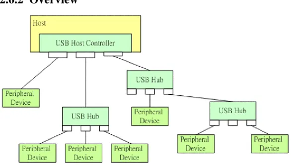
Figure 2.7: USB Network Topology
Figure 2.7 is the network topology of USB system that is host controlled. There are up to 127 devices, which can be connected to a single USB bus by using USB host controller, for example, the PC and USB hubs. A root hub (the host controller of Figure 2-7) can directly connect up to 7 USB hubs, and each hub on the root hub can be, in turn, connected to seven hubs, etc. to a maximum of seven tiers and 127 ports. This kind of network topology is generally called tiered star topology. A “Compound Hub” in USB standard means a USB peripheral device has a USB hub build into it, so it is comprised a function and one or more hubs. Besides, USB supports
plug-and-play and hot plug; therefore, if you plug the device directly, it will be configured automatically. Besides, the maximum length of USB cable is up to 5 meter.
There are two speed modes in USB v1.1 – 1.5Mbps (Asynchronous mode) and 12Mbps (Isochronous mode). USB v2.0 provides higher performance than USB v1.1. The speed of USB v2.0 is promoted to 480Mbps current, and it is also downward compatible with USB v1.1 speed modes. So when the peripheral device does not support USB v2.0 speed mode, USB v2.0 host will use the lower speed mode of 1.5Mbps or 12Mbps determined by peripheral device to work with it. Besides, USB v2.0 also supports a special transmission mode – OTG (On-The-Go). OTG is a specification allowed USB peripheral device can communicate each other without host. The more detail please refers to On-The-Go v1.0 specification [25]. And some related collections of USB technology is listed in [24].
2.2.7 RS-232
2.2.7.1 History
RS-232 was introduced in 1960, and is currently very common and widely used communication interface especially in PC and Industry field. It is standardized as EIA232 by EIA (Electronic Industries Association) [27]. The third version is RS-232C which is the standard of choice of PC in 1969. The fourth revision called RS-232D adopted in 1987. The newest version is named EIA232E introduced in 1991.
2.2.7.2 Overview
RS-232 is simple and low-cost network interface. It is a single-ended data transmission system. It uses a single wire for data transmission. So it is much useful to support two-way communication using two wires: one is for receiving data, another is for transmitting data. RS-232 utilizes the negative logic to identify the signal status (or logic status). In this case, it uses the negative voltage level (-3V to -12V) to represent ‘1’, positive voltage (+3V to +12V) to represent ‘0’.
Figure 2.8: RS-232 data frame format
Moreover, RS-232 uses the asynchronous mode as its data transmission mode. So it needs a start bit for representing the start of data packet and a stop bit to represent the end of data packet. Besides, the length of data packet of RS-232 can be 5,6,7 or 8 bits. Furthermore, it also can add a parity bit, which can be odd or even parity bit form for error correction. The speed of RS-232 can be 1200bps, 2400bps, 4800bps, 9600bps, 19200bps, 38400bps, 57600bps, 115200bps or higher. Figure 2.8 depicts the brief waveform of RS-232 signal.
2.3 Wireless Technologies
2.3.1 Wireless LAN - 802.11
2.3.1.1 History
IEEE 802.11[28] is a very popular WLAN (Wireless Local Area Network) standard in the world and the responsibility of IEEE 802.11 Working Group is to develop the international standards for WLAN. And the Wi-Fi Alliance is the wireless standard group formed in 1999 to certify interoperability of WLAN products base on IEEE 802.11 specification. And now, there are many standards developed by IEEE 802.11 Working Group such as 802.11b, 802.11a, 802.11b etc. The 802.11b standard is the first finalized specification in September, 1999 by IEEE 802.11 Task Group b and it is current very popular and already has many compliant products in the world.
2.3.1.2 Overview
IEEE 802.11b chooses DSSS (Direct Sequence Spread Spectrum) as its modulation scheme in the physical layer. Its operation frequency band is 2.4GHz, the unlicensed ISM (Industrial Scientific and Medical) band, and the maximum data rate is up to 11
Mbps.
IEEE 802.11a is another standard version of WLAN. It chooses the OFDM as its modulation scheme and the maximum data rate is promoted to 54 Mbps. But it chooses the 5GHz band to be its operation frequency band. The 5GHz band has less interference than 2.4GHz band but not the unlicensed band in each country. By description above, we can know IEEE 802.11b and 802.11a are incompatible due to they adopt the different modulation scheme and operation band.
IEEE 802.11g is the standard focus on downward compatible with extension to the existing IEEE 802.11b and improves the data rate exceed 20Mbps. Due the MAC (Medium Access Controller) of IEEE 802 share a common LLC (Logic Link Controller), so all the services, such as the file sharing, http, e-mail etc. in the wired Ethernet, are made available to wireless Ethernet too.
IEEE 802.11 adopts the CSMA/CA (Carrier Sense Multiple Access/Collision Avoidance) as its MAC protocol. CSMA/CA is similar to CSMA/CD in the wired Ethernet MAC. It like CSMA/CD utilizes a “listen before talk “ mechanism to control access to share the same medium. But there no way to make sure that there is no collision between wanted client/receiver and server/transmitter due to it is possible existed a “hidden” node which wants to transfer data to receiver and is within range of the receiver but out of range of the transmitter. So we cannot monitor the idle or busy state of the medium while transmitting. Therefore IEEE 802.11 adopts the CSMA/CA can solve the above problem efficiently to replace CSMA/CD. The more detail information please refers [28][30][31].
2.3.2 BlueTooth
2.3.2.1 History
BlueTooth SIG (Special Interest Group) [32] was founded by Ericsson, IBM, Nokia, Intel, and Toshiba in February 1998. The mission of BlueTooth SIG is to develop an open standard for short-range wireless technology called BlueTooth. L. M. Ericsson of Sweden invented BlueTooth technology first in 1994. The first version of specification, BlueTooth V1.0b, is released in December 1999 and the second reversion, BlueTooth V1.1, in February 2001. Moreover, the second version is downward compatible to v1.0b.
2.3.2.2 Overview
BlueTooth is an open standard version of WPAN (Wireless Personal Area Network). Identical to IEEE 802.11b, BlueTooth v1.x adopts 2.4 GHz as its operation frequency band but it utilizes FHSS (Frequency Hopping Spread Spectrum) as its modulation scheme. However, compared with IEEE 802.11, BlueTooth has different market partition The hopping frequency of BlueTooth is 1600 hops per second, the frequency spectrum is normally divided into 79 channels with 1 MHz channel spacing per channel. The maximum of transmitting distance is up to 10 meter at 0 dBm transmitter RF power and up to 100 meters at 20 dBm.
BlueTooth supports two data transfer modes, one is ACL (Asynchronous Connection-Less) for data packet, and the other is SCO (Synchronous Connection-Oriented) for voice packet. The maximum of data rate of ACL is up to 723.2 kb/s asymmetric (and still up to 57.6 kb/s in the return direction) and up to 433.9 kb/s symmetric.
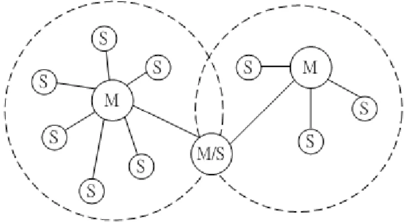
Figure 2.9: BlueTooth Scatter net Network Topology
The network topology of BlueTooth is a master-slave based Ad-Hoc network. It supports up to 7 slaves with a single master in a piconet organized into groups of two to eight devices, consisting of a single master and one or more slave devices. A device in a piconet may additionally belong to more than one piconet, either as a slave in both or as a master in one piconet and a slave in another. These devices are bridges to connect the different piconets and form the expanded the network topology called scatter net that is shown in Figure 2.9.
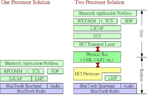
Figure 2.10: BlueTooth Protocol Stack
Figure 2.10 is BlueTooth protocol stack, the left of this figure is the One Processor Solution architecture and the right hand side is the Two Processor Solution architecture that means it has another processor as a host (usually called host controller) to control BlueTooth module at the remote side. The Two Processor solution uses the HCI (Host Controller Interface) interface to separate the protocol stack of the One Processor solution into host and remote sides. The HCI provides the uniform interface for different physical bus such as USB, UART, PC Card, etc. In this case, you need to choose the suitable HCI transporter layer standard and implement the HCI transport layer depending on different physical bus. Accordingly, host controller can communicate with BlueTooth module through HCI protocol through certain physical bus.
Each layer of the protocol stack of BlueTooth is very important and its responsibility for different functions. For example, the (Logical Link Control and Adaptation Protocol) L2CAP provides protocol multiplexing which allows different upper protocols, some of them are belong BlueTooth such as RFCOMM which emulate serial port which allows the legacy software can operate on a BlueTooth device, TCS (Telephony Control Protocol Specification) which provides for voice and data call control and SDP (Service Discovery Protocol) which provides a discovery mechanism to discover which BlueTooth specific services is available provided by
nearby BlueTooth devices, and the others are implemented by 3rd party company such as TCP/IP. The L2CAP layer also provides the fragmentation and reassembly of packets between layers, and negotiation and monitoring QoS (Quality of Service) between devices.
BlueTooth SIG also defines many profiles to ensure the interoperability between products from different companies. In the viewpoint of end user, the profiles ensure the common experience. In the viewpoint of application developer, the profiles specify the combined procedures from many basic standards, and reduce set parameter in basic standards. Each profile will lists the required protocol layers including BlueTooth specified such as base-band, LMP, L2CAP, SDP, RFCOMM, etc. and 3rd party specified such as TCP/IP, WAP, etc. Please refer [32][33][34][35] to get more details about BlueTooth technology.
2.3.3 HomeRF
2.3.3.1 History
HomeRF Working Group [36] was formed in 1997. The major members are Compaq, Ericsson, HP, IBM, Microsoft, Motorola, Philips, Proxim, and Symbionics. The main goal of this group is to enable the wireless data and voice networking within the home. HomeRF v2.0 is released in 2001.
2.3.3.2 Overview
HomeRF compared with the other wireless technologies, such as BlueTooth and IEEE 802.11, is the wireless technology focus on home networking at the consumer price points. HomeRF combined three technologies - IEEE 802.11, OpenAir, and DECT to provide a complete solution for wireless home networking. It integrates the data, voice, and media streaming in home networking. The voice channel is simultaneously up to 8 channels. It also incorporates the DECT (Digital Enhanced Cordless Telephony) standard, and provides a range of up to 150 feet currently. The speed of data rate is 10-20Mbps+ in HomeRF v2.x.
The same as BlueTooth, HomeRF also adopts the FHSS (Frequency. Hopping Spread Spectrum) technology as modulation scheme in 2.4GHz band due to FHSS is more interference immune than DSSS. And it also plans to use Adaptive FH
(Frequency Hopping) to avoid static interference to ensure the peak performance. The MAC layer of HomeRF utilizes the CSMA/CA for data transferring, and the TDMA (Time Division Multiple Access) for delivery of voice traffic. It will be full compliance with IEEE 802.11a at 54Mbps for 5GHz band in the future version. The future version will be downward compatible with all previous released versions. It also supports the QoS and security. The issue of coexistence of existing wireless standards is also considered in HomeRF.
Chapter 3.
Home System Standards
3.1 Introduction
We have already introduced many home networking interface standards in Chapter 2. Then we want to give you an overview of the trend of the home system standards in this chapter.
A home system, which can be called “Framework” or “Middleware”, is system architecture to manage the services of the home appliances. Refer to the explanation of the Xilinx White paper [37] - “The home networking middleware is a layer of software that lies on top of an information appliance operating system. It provides “hook” of APIs to which home networking appliances can be attached”. On the other hand, each home appliance can access services and share resources with each other through home system. Besides, some of home system standards provide the capability of the multimedia service too. In conclusion, the home systems connect with all home appliances and manage all services of those appliances, so end users can access all services and share resources in the home network.
Figure 3.1: Home systems choice in 2002 [38]
In recent year, there are many home system standards, such as OSGi, UPnP, Jini and so on, are proposed and developed the related products around the world. As shown in Figure 3.1, we can see the choices of home systems in 2002. [38] Because there are so many choices of home systems especially in North America, it will confuse us to choose the suitable one. The Europeans have observed the phenomenon and start to combine three competing home systems in Europe into one called Konnex. Besides, HES (Home Electronic System) is an international home system standard, but it is not accomplished yet. The primary objective of HES is to provide a specify hardware and software that enable a manufacture to make only one version of product for connecting with other home networking standards. The more details are introduced in Section 3.3. Moreover, OSGi standard is similar with HES. It proposes a service framework running on the residential gateway to integrate all services provides by home appliances of multiple different home systems. The more details are described in Section 3.2. Furthermore, we introduce some representative home system in the remaining sections.
3.2 OSGi
3.2.1 History
OSGi (Open Service Gateway initiative) was founded in March 1999. There are over 60 members including Ericsson, Cisco, Nokia, Siemens, Sun Microsystems, and IBM. The fist version, OSGi SPR1, was released in May 2000, and the second version,
OSGi SPR2, in October 20001.
Figure 3.2: OSGi Gateway [44]
3.2.2 Overview
OSGi is a standard to integrate whole home appliances into a residential gateway by services. In Figure 3.2, we can see that OSGi attempts to integrate not only home networking interfaces but also home systems. It provides a open architecture for service providers, service aggregator, service gateway provider, WAN provider, Internet service provider, appliance manufacture, equipment manufacture, and home network system developer [38][42][44]. In other words, it will create a new business model and bring huge market.
3.2.3 Feature
The main features of OSGi are described following [37][42][43]:
Platform Independent: OSGi only defines a set of API (Application program interfaces). The API can be implemented by any hardware platforms and operating systems. Besides, it adopts Java technology as its main choice for implementation. Java is an excellent solution with the
feature of platform independent. In this case, anyone is able to develop OSGi product individually and the interoperability can be ensure too.
Security: OSGi specification provides many levels of security features, ranging from digital signing of downloading modules to fine-grained object access control.
Multiple services: OSGi supports the multiple services from different service provider on one service gateway. It provides the flexibility to allow a gateway operator to offer wide services to customers.
Multiple local network and data access technologies: The emerging technologies- the local network, such as Jini and HAVi, and the data access technologies, such as BlueTooth, IEEE 1394 and HomeRF, are all supported by OSGi specification. All of them can be cooperated and added in OSGi platform.
Coexistence with other standards: OSGi tries to define a specification to integrate whole emerging and former standards together. In other words, OSGi is not an independent standard but is a standards which to make interoperability and coexistence with other standards.
3.2.4 Architecture
As shown in Figure 3.3, OSGi end-to-end architecture, we can see the overview of the relationship between major entities. The major entities are explained individually following:
Service gateway: The service gateway is the central component of OSGi and is the OSG (Open Service Gateway) in Figure 3.3. It is the gateway, which acts as the bridge between wide area network and internal network, and is attached to WAN to connect the external service provides to internal clients. The OSG is secure, zero-administration device to connect to devices on the local network. Its purpose is to provide communication between local devices and devices and services on the WAN. Besides, it acts as the service manger to services that operate on it.
Service provider: The service provider contains a set of services and provides them to OSG. If OSG operator trusts a service provider, the services can be downloaded securely by OSG and installed on it from this service gateway.
OSG operator (Gateway operator): The OSG gateway operator is responsible for managing and maintaining OSG and its services. Some functions of its are listed following:
Download, start/stop, update and remove a service Gateway management
Link security between WAN and OSG
Check the validity and the rights of any dependencies that one service may have on other services
Manage services Etc.
Wide area network and carrier/ISP: WAN (Wide Area Network) provides the necessary communication service provided by ISP among OSG, service gateway, OSG gateway operation, service aggregator, and remote terminals. Therefore, OSG can connect to WAN through the carrier/ISP.
Local devices and networks: The local devices are attached to OSG by connecting with hardware interfaces, for instance, parallel or serial connections directly or various home networking interfaces such as BlueTooth, IEEE 1394 or Ethernet indirectly.
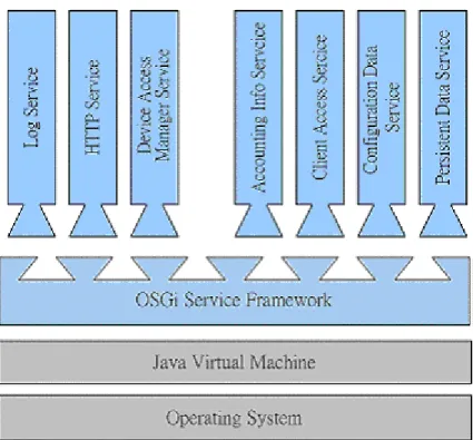
Figure 3.4: OSGi Framework Architecture
Figure 3.4 shows the framework architecture of OSGi, which is the service framework running on top of Java virtual machine. OSGi provides the execution environment for services that may be packaged as a bundle, which is a Java jar archive. The bundle consists of Java classes and some necessary data needed by these services. In Figure 3.4, the items above OSGi service framework are some important services defined in OSGi specification. Each of them will be briefly introduced briefly following [42][43][44]:
Persistent data service: The persistent data service provides a set of APIs to help a service to store and retrieve information from other services. Therefore, you do not have to implement a code to efficiently store and retrieve information to a file system and recover form error. You just need to implement a common persistence data service to provide other services to store and retrieve information. That is, a service can utilize API to search the persistent information store by a high level query language recover from failure after partial updates, and synchronize the data with a server database. Besides, implementing persistent data service can provide a mechanism to backup the persistent information on the server as an extra measure of reliability.
Configuration data service: Many services need more additional configuration information to perform their task. The configuration data service can provide the common service API for the services to store and access the configuration data and a means by which a remote administrator can change configuration information.
Client access service: The client access service provides an interaction mechanism for end users to access the services on OSG. For instance, you can maintain the services from remote server or access the services from client terminals, such as mobile phone and PDA.
Accounting info service: In OSGi Release 2.0, it has defined the accounting info service to provide a charging mechanism depending on service usage. For example, the power energy company can use the accounting info service API to charge for the bill of power usage.
HTTP service: The HTTP service provides an API for the HTTP based web server, which runs as a part of OSG. Hence, you can use the API to configure the server, publish static content, and publish dynamic content generated from Java serverlet.
Device access manager service: The OSG can on-demand, dynamically download related services for devices and the home networking hardware connected to OSG by the device access manager service. Besides, the service provider can access and communication with devices without being burdened with low-level communication details. The device access manager service has two major components: one is device bundle, which is dedicated for communicating with special type of device, and the other is network bundle which is dedicated for communicating with devices attached to the network. The network bundle may contain the needed protocol stacks, drivers, and the other resources. The device access manager service has following features:
Network Independent – If a new network needs to be supported by the device access service, you only need to add the new network bundle. Device Independent - If a new device needs to be supported by the
Automatic Discovery – The device access service will support the feature of automatically detecting the new device or network, when they are attached to the OSG. Besides, the new bundle, which belongs to the new device or network, will be downloaded and installed with the minimum user interactions.
Log service: The log service provides that the Java-based OSGi services can write the entries to a log and read the entities from log in consistent way. Moreover, the log service is platform independent. The log service has the following general features and capabilities:
Records the current system time, the severity level, the calling bundle id, the text message and an optional Java Throw-able object that describes the exception condition in the log entry.
Records the identity of the Java Program running on the framework, which created the log entry.
Listens to framework events that Release 2.0 has defined the concise definition of the output format and create log entries representing these events.
Reads past log entries via an enumeration
Notifies the listeners of log entries as the entries are created
3.2.5 Related reaches
Actually, there are many OSGi related open source projects and commercial solutions in the world. We generally list some of them in Table 3.1. [44] [48] [49] [50] [51]
Open Source
Project Description
OSCAR Oscar project implements OSGi specification. It is a platform for experimenting with service-oriented computing approaches. [45]
Mister Bundles The goal of the "Mister Bundles" project is to implement Mister House-like services coded with Perl under the form of OSGi bundles (java code), compliant to OSGi v2.0 framework specifications. [46]
Oxygen Oxygen is an OSGi gateway implementation in Java. It is designed to run on small footprint and embedded devices that run a Sun J2ME. [47]
Commercial Solution
Company and Solution Description
Sun – JES [48] JES (Java Embedded Server) is provided by Sun. It is the key tool to develop OSGi-based products and a small footprint application server that can be embedded into a network device. JES is fully coded by Java and the newest version is JES 2.0 now. Please refer [48] to get the more details.
IBM – VisualAge Micro Edition [49]
IBM company has released the version 1.2 of VisualAge Micro Edition, which supports interactive OSGi bundle management and real-time Java components. Please refer [49] to get more details.
Ericsson – OSGi development tools
Ericsson has published the E-box, the first OSGi based product, in late 1999. And now, Ericsson offers two development tools: one is Residential e-Service-Application Development Package 2.0 and the other is Automotive e-Service – Software Development Kit to help developers to develop OSGi applications running on Ericsson e-Server system. Please refer [50] to get more details.
Gatespace – SGADK Gatespace was founded in 1999 with Ericsson and Swedish research and consulting company Carlstedt Research & Technology (CR&T). Gatespace provides the tools: GDSP (Gatespace’s Distributed Service Platform) and the subset of GDSK - SGADK (Gatespace’s Service Gateway Application Development Kit) based on the Ericsson e-Service system. Therefore, developers can use them to develop OSGi based application. Please refer [52] to get more details.
Table 3.1: OSGi Related Projects
Furthermore, there are several related researches about OSGi. Someone has developed the solution to integrate current home system standards, Jini and UPnP, into OSGi system. [52] Currently, they have completed Jini-to-OSGi and UPnP-to-OSGi
transformation technologies. Prosyst Software AG has announced their implementation of OSGi. [53] It has integrated with many existing home networking standards. Moreover, there are two theses focused on the special topics of OSGi. One [54] implemented OSGi platform, X Service Gateway. It has integrated X10 home system based on Linux platform. And the other [55] adopted Sun JES 2.0 as its OSGi base to implement their OSGi platform.
3.3 HES
3.3.1 History
HES (Home Electronic System) [55] is an international home system standard proposed by the Working Group 1of ISO/IEC. The Working Group is officially called ISO/IEC JTC 1/SC 25/WG 1. WG1 has experts coming from different countries including United States, Germany, Europe, Japan, and Korea. HES does not accomplish the standard specification yet. It just announces the related technical reports [55].
3.3.2 Overview
HES specifies a platform with hardware and software that enable a manufacture to offer one version of product that can connect with various home networking systems. Following components are defined in HES draft [57]:
Universal Interfaces: An interface module is incorporated into an appliance for communication with various home-networking systems.
Command Language: A language is used for appliance-to-appliance communication independent of carrying message by what kind of home networking systems.
HomeGate: A residential gateway standard provides a bridge between local network and WAN. In other words, device connected with local networks can access Internet resources via HomeGate. Moreover, authorized vendors or users can access the local services through it remotely.
3.3.3 Components
3.3.3.1 Universal Interface
Figure 3.5: Appliances connect to Home Electronic System [57]
HES proposes a new home system, which can connect with any home automation network. Therefore, HES proposes a UI (Universal Interface) component that is incorporated into appliance and that has a standard data plug. Besides, every appliance that connects to the home automation network has a NAU (Network Access Unit), which is responsible for converting the data signal and appliance message to a particular home automation system protocol. Figure 3.5 depicts the architecture of UI. Also, HES specifies the communication protocol between UI and NAU [57].
3.3.3.2 HomeGate
Figure 3.6: An example of HomeGate implementation [57]
HES also proposes a residential gateway solution – HomeGate. HomeGate plays the role of bridge between the local network and the external network (WAN). Moreover, HomeGate needs the firewall features to support the security and limits the types messages out and in the house. However, HES does not constrain how to implement HomeGate actually, but its suggested implementation is a box with plug-in cards as shown in Figure 3.6. In this case, HomeGate contains many home networking cards depending on different kinds of network interfaces used by WAN and LAN. Moreover, there are many home-networking protocol now, so HomeGate needs to add more LAN adaptors to translate the protocols among various local home networks. [57]
3.4 HAVi
3.4.1 History
HAVi (Home Audio Video Interoperability) organization [58] was founded in November 1999. The goal of HAVi association is to develop a home network standard based on IEEE 1394 network for interoperability and the multimedia data transmission among digital audio and video devices. In addition, Panasonic, Hitachi, Sony, Sharp, Toyota and Philips are members of HAVi association. The fist version,
HAVi v1.0, was released in January 2001.
3.4.2 Overview
Vendor Specific Platform IEEE1394 Network CMM Message System S tream Ma na ge r Re sour ce Ma ng er Eve nt Ma na ge r Re gi stry DC M Ma na ge r DCM DCM DCM DCM Application Application Havlet Havlet
Interoperability APIs
Platform Specific APIs
Havlet
Figure 3.7: HAVi Architecture
HAVi is a home system for seamless interoperability among digital audio and video consumer electronics (CE) devices. Besides, HAVi organization defines a set of API to help developer to develop HAVi-based applications based on HAVi framework. Figure 3.7 depicts HAVi architecture; we can see HAVi is the software framework which comprises many system elements based on IEEE 1394 network. We describe each element of HAVi system briefly as follows [37] [58] [59] [60]:
Message System: Message System provides communication facilities between HAVi software elements. It is independent of the network and transport layers.
CMM: CMM (Communication Media Manger) is platform dependent. It provides the asynchronous and isochroous communication over IEEE 1394 network.
Registry: It is responsible for managing a directory of software element available within HAVi network. Therefore, a software element can locate
other software elements on the network and detect its capabilities and properties.
Event Manager: It is the event delivery service. Hence, Event Manager handles whole events of the software elements of HAVi system. For instance, delivering a local event to a specific device or a global event to all devices on HAVi network.
Resource Manager: It facilitates sharing and allocation of resources and scheduling of actions.
Stream Manager: It is responsible for managing the multimedia streaming service among A/V devices over IEEE 1394 network.
DCM: It provides an interface of controlling general functions of a single device. It also exposes HAVi defined API for HAVi devices. Moreover, DCM is a software element that can be dynamically downloaded, removed and installed in HAVi network.
FCM: FCM is contained within DCM. It represents each controlling function of a device. Besides, it is vendor specific.
DCM Manager: DCM Manager is responsible for installing and removing DCM.
Havlet: Havlet is a HAVi application written by Java. It offers a user interface for end users to control HAVi-base devices.
Application: The application dependents on HAVi system and it can communicate with other software elements by mechanisms above.
3.5 Jini
IP Network Operating System Java Virtual Machine
Jini Technology Services Services
Figure 3.8: Jini Architecture
3.5.1 History
Jini [61] is a home system technology promoted by Sun Microsystems. Jini attempts to solve the interoperability of home appliances. It is announced during 1999.
3.5.2 Overview
Jini is similar to OSGi and HAVi; it is a middleware running on each device, which embeds the Java runtime environment as shown in Figure 3.8. Following lists the main features of Jini [37]:
Platform independent: In Figure 3.8, we can see that Jini is a java program running on top of Java virtual machine, so it can get the platform independent feature of Java.
Small footprint: To implement Jini solution requires very small code size even can be embedded into any type of home appliances. Sun Microsystems has implemented Jini into the coffee maker and the lamp.
Plug and Play: Jini provides the mechanisms, lookup service, discovery and join-in protocols, to support the feature of Plug-and-Play. Therefore, the end users can access any service of home appliance with few interactions. Legacy device support: Jini utilize the proxy architecture to integrate the
legacy devices into Jini network. Accordingly, Jini-based devices can access the services of the legacy devices through Jini proxy server.
3.6 UPnP
UPnP Vendor Defined
UPnP Forum Working Committee Defined
UPnP Device Architecture Defined
HTTPMU (Discovery) HTTPU (Discovery) SOAP (Control) HTTP (Description) UDP TCP SSDP GENA SSDP IP HTTP GENA (Events) Physical buses ---IEEE 1394, PCI, USB, etc.
Internet Protocol ---Ethernet, HomeRF, HomePNA, etc. IrDA ---IR HomePlug, X10 ---Power Line … -…
Figure 3.9: UPnP High Level Architecture [37] [63]
3.6.1 History
UPnP Forum [62] was formed by a group of companies in October 1999. Microsoft is the key player of UPnP Forum. The goals of UPnP Forum are to enable the simplify the implementation of network emergence of easily connected devices and to ks in the home and corporate environments.
3.6.2 Overview
Figure 3.9 illustrates the high level architecture of UPnP. We can see that UPnP comprises many industry standards including TCP/IP, DNS, HTTP, HTML, UDP,
LDAP, XML, XSL and ARP. Each protocol is responsible for special function. For instance, XML is used to represent the standard device and service description, HTTP is responsible for communication protocol among devices and so on. UPnP has following features [37]:
Plug and Play: UPnP adopts the combination of industry protocols, such as XML, HTTP, SSDP, SCPs, etc., to cooperate the feature of Play and Play. Therefore, uses can access the services of UPnP-based devices with the interactions as less as possible.
Platform Independent: UPnP is independent of any operating system and physical device. It is running on top of IP layer. Therefore, UPnP can be implemented into any device supporting IP network.
Small footprint: UPnP can be implemented into the device with few RAM and ROM size. Typically, these devices consist of low-priced microcontroller, 200-1000 Kbytes of RAM and flash ROM [37].
Integration with legacy and non-IP devices: The devices, without capability of sufficient hardware resources, can be also integrated with UPnP by UPnP-based bridges. So legacy devices and non-IP devices can share UPnP resources with each other via UPnP-based bridges.
Peer-to-peer network architecture: UPnP is a peer-to-peer network architecture; it means that it does not need the central control device to handle whole interactions among UPnP network. In other words, each device can directly communicate with others.
3.7 X10
3.7.1 History
X10 Ltd. [64] is a USA company who designs and markets home automation devices based on X10 protocol. Pico Electronics in Scotland developed X10 protocol. X10 patent expired in December 1997. Therefore, X10 protocol is now an open standard. Moreover, the industry leaders including RCA (Thomson), Radio Shack, IBM, and others, market X10 compatible products presently.
3.7.2 X10 Protocol
Figure 3.10: Waveform of binary data using X10 PLC [65]
X10 protocol first was developed for PLC (Powerline Carrier Technology). It utilizes the existing power lines of home as its network medium. Currently, it also supports the different medium: wireless RF and infrared. We introduce X10 protocol for PLC in this section. X10 transmits the binary data over the powerline by a 120KHz signal pulse for 1ms at the zero crossing point of the AC sine wave as shown in Figure 3.10. For reason of reducing error rate, it adopts two zero crossing points to transmit one binary data, either “1” or “0”. The binary data, “1”, is represented by a 120 KHz pulse at the first zero crossing point and no pulse at the second crossing point. The binary data, “0”, is represented by no pulse at the first zero crossing point and a 120 KHz pulse at the second zero crossing point [65].
Figure 3.12: The Waveform of X10 “Start Code” [65]
A basic X10 message consists of 13 bits. The format is shown in Figure 3.11. It comprises 4-bits start bit, a 4-bits house code, 4-bits unit/function code, and 1 bit function bit. The start code is consecutive three pulses followed by no pulse to differentiate itself from regular data bits as shown in Figure 3.12. Moreover, the function bit indicates whether the previous 4 bits should be interpreted as a unit code or a command code. You can refer [65] to get the more details about X10 protocol.
3.8 Others
There are many home system standards including proprietary standards, United States Standards, open standards offered by companies and consortia and international standards. For instance, CEBus [87] and LONWORKS [88] are popular United States Standards. ECHONET [86] is an open standard promoted by Japanese companies. You can refer [38] [39] to get more details of other standards.
Chapter 4.
eHome System
4.1 Introduction
Figure 4.1: eHome Home System Architecture
In Chapter 3 and Chapter 2, we have already introduced many home systems and interface in home networking area. According to the trend, we can see that it is impossible to construct a home network system by the only one existing home system standard and interface. Moreover, we believe that there will be more and more home networking systems and interfaces will coexist in future home. Thereby, we try to
propose a new home system – eHome. The architecture is shown in Figure 4.1. The features of eHome system are low-cost, easy to construct, and high scalable and flexible. It is also integrated with the portable devices, which provide capability of remote access and the existing home systems and network interfaces. Moreover, whole existing home systems and interfaces will be cooperate through an eHome system.
The remaining sections of this Chapter are structured following. Section 4.2 will introduce some related projects in recent year. Their consideration in designing, proposed approaches and characteristics of proposed architecture will be also discussed. In Section 4.3, we will discuss and address the whole considerations in designing our eHome system. In Section 4.4, we will present our new home system – eHome. Section 4.5 describes the system components of eHome system. Finally, Section 4.6 defines eHome protocol and its characteristics.
4.2 Related Projects
4.2.1 VSG Based Home System
The VSG (Virtual Service Gateway) based home system is a framework architecture proposed by Eiji Tokunaga, Hiro Ishikaeam, and others [64]. This framework is dedicated for integrating heterogeneous home systems. It provides a desirable environment in which service based on every home system can connect any other services transparently. Moreover, a new home system can be connected to this framework without too much effort. Here home systems are also called middleware.
Figure 4.2: Overview of VSG based Framework
Figure 4.2 is the illustration of this framework. In Figure 4.2, each middleware has three main components: VSG (Virtual Service Gateway), Protocol Conversion Manager, and VSG protocol. Virtual Service Gateway connects a middleware to another middleware by certain protocol that decides the information of services such as interfaces, locations and data. Protocol Conversion Manager used to convert the local middleware protocol into protocol of Virtual Service Gateway and also VSG into local middleware. The VSG protocol is chosen depend on demand of how to integrate services. The service could be a multimedia streaming, a voice communication, or an action command. Lastly, Virtual Service Repository, a database, which has a lot of information of different middleware such as service locations and service contexts. The current status of implementation of this framework will be introduced in the following paragraph.
Figure 4.3: Prototype of VSG based Framework Implementation
They chose SOAP that is XML/HTTP-based protocol as the VSG protocol currently and utilize the Apache SOAP, a product of IBM developer works for current VSG prototyping. Figure 4.3 is the illustration of current prototype of their implementation. This prototype has integrated existing home systems: X10, Jini and HAVi. Please refer to [64] to get more details.
![Figure 2.3: HomePNA Data Frame Format [8]](https://thumb-ap.123doks.com/thumbv2/9libinfo/8656997.194528/20.892.135.764.590.764/figure-homepna-data-frame-format.webp)
![Figure 2.5: HomeCNA Networking Topology [18]](https://thumb-ap.123doks.com/thumbv2/9libinfo/8656997.194528/22.892.173.723.864.1102/figure-homecna-networking-topology.webp)
![Figure 2.6: HomeCNA : Five Networks – one cable [18]](https://thumb-ap.123doks.com/thumbv2/9libinfo/8656997.194528/23.892.167.729.379.609/figure-homecna-networks-cable.webp)
![Figure 3.1: Home systems choice in 2002 [38]](https://thumb-ap.123doks.com/thumbv2/9libinfo/8656997.194528/34.892.189.707.107.386/figure-home-systems-choice.webp)