Wen-Shing Lee
National Taipei University of Technology, Department of Air-Conditioning and Refrigeration Engineering, 10673, Taipei, Taiwan, R.O.C.
Bo-Ren Chen
Sih-Li Chen
1National Taiwan University, Department of Mechanical Engineering, 10673, Taipei, Taiwan, R.O.C.
Latent Heat Storage in a
Two-Phase Thermosyphon Solar
Water Heater
This article experimentally studies the thermal performance of latent heat storage in a two-phase thermosyphon solar water heater, which utilizes the superior heat transfer characteristics of boiling and condensation, and eliminates drawbacks found in the con-ventional solar water heater. Experimental investigations are first conducted to study the thermal behavior of tricosane (paraffin wax 116), water, and sodium acetate 共NaCH3COO · 3H2O兲 used as energy storage materials. The results indicate that tri-cosane provides many advantages to be the energy storage material in the latent heat storage system. This study also examines the functions of charge and discharge thermal behaviors in a two-phase thermosyphon solar water heater. The results show that the system gives optimum charge and discharge performance under 40% alcohol fill ratio and with tricosane used as the energy storage material, and displays an optimum charge efficiency of 73% and optimum discharge efficiency of 81%. 关DOI: 10.1115/1.2147588兴 Keywords: energy storage material, two-phase thermosyphon, solar water heater
1 Introduction
A number of solar water heaters关1兴 have been considered and developed in recent years. Most solar water heaters utilize an active control method to store or release thermal energy. That is, in designing heat storage, a pump is included to transfer thermal energy from the collector to the thermal storage tank via flowing working fluid. To utilize the stored thermal energy, an electromag-netic valve is used under control to change the flow path of the working fluid, so that energy stored in the storage tank is released to the domestic water. There are two drawbacks found in such solar energy systems. First, the thermal storage shall be unusable in case of pump or electromagnetic valve failure. Second, the charge and discharge ability of the conventional storage systems basically relies on the system piping design, and therefore, only two functions, energy storage and energy release, are available in its operating modes.
The objective of the present article is to provide a two-phase thermosyphon solar water heater关2兴 in which a passive type of control is adopted to eliminate the above drawbacks found in the conventional solar heating systems. Moreover, apart from storing and releasing energy, the proposed solar water heater also allows for operation of the energy supply side and energy use side at the same time关2兴. The two-phase thermosyphon solar water heater, as shown in Fig. 1, mainly includes an energy storage tank and two-phase thermosyphon loops. The energy storage tank is filled with energy storage material共ESM兲. The thermosyphon loops include three parts, namely, a group of parallel fin tubes vertically dis-posed inside the storage tank, the vertical collector tubes located outside of the tank and a horizontal double pipe heat exchanger situated at the upper region inside of the storage tank. An adequate amount of working fluid is filled in the thermosyphon loops. The parallel fin tubes combine the collector tubes to form a two-phase closed loop thermosyphon for thermal storage. The thermal re-lease process is achieved by connecting the parallel fin tubes and the double pipe heat exchanger to form a two-phase closed ther-mosyphon.
Figure 1共a兲 shows the function in which the system operates to store thermal energy. The working fluid, ethyl alcohol, inside the collector tubes, having absorbed solar radiation, becomes boiled and produces gaseous working fluid which flows upward due to its buoyancy into the double pipe heat exchanger and then downward into the parallel fin tubes. The alcohol vapor condenses and re-leases heat to the ESM outside of the parallel fin tubes. The con-densed working fluid flows downward along inner surfaces of the parallel fin tubes under gravity and into the lower header, and finally into the collector tubes to complete charge cycle.
Figure 1共b兲 shows the manner in which a system operates to release thermal energy. When the cold water enters the internal tube of the double pipe heat exchanger, ESM will release heat. The liquid working fluid in the parallel fin tubes absorbs heat stored in the ESM and becomes boiled to produce vapor working fluid which flows upward due to its buoyancy. As heat is trans-ferred to cold water, the vapor working fluid undergoes conden-sation on the outside of the internal tube of double pipe heat exchanger. Then the condensate flows along the wall of parallel fin tubes, absorbs heat from ESM and becomes boiled to complete discharge cycle.
The distinguishing feature of the proposed integral collector-storage system can make the thickness of the solar water heater thinner and the weight of storage tank lighter, as compared with the conventional heating system. Thus the cubic configuration of the present design could be utilized in many applications where the conventional solar collectors cannot be applied. For instance, it can be readily installed as the wall or roof of a building, which better utilize the space of the building and reduce the solar heating load to the building. It is very suitable in Taiwan, where the cool-ing load for an air conditioner comes mostly from solar heatcool-ing. It is also suitable for regions where the water quality is very poor; for example, at the south part of Taiwan people use solar energy to heat underground water. Scaling would take place inside of the storage tank in the conventional solar collectors, which results in bad heat transfer and corrosion problems. In the proposed energy storage system, the double pipe heat exchanger is used to release the stored heat from the storage tank to the cold water. It can prevent the corrosion inside of the storage tank.
Many factors affect the thermal performance of a two-phase thermosyphon solar water heater关2兴. In view of the application, we focus on the choice of ESMs. In this paper, two experimental
1
Corresponding author.
Contributed by the Solar Energy Division of ASME for publication in the J OUR-NAL OFSOLARENERGYENGINEERING. Manuscript received April 28, 2004; final manu-script received January 25, 2005. Review conducted by Aldo Steinfeld.
systems are developed. In the first experiment, the thermal behav-iors of three ESMs, including tricosane 共paraffin wax 116兲, so-dium acetate 共NaCH3COO · 3H2O兲, and water are investigated. Applying the results from the first experiments, the thermal per-formance of a two-phase thermosyphon solar water heater is ex-perimentally described. This study also examines the effect of the alcohol fill levels on the charge and discharge characteristics in the proposed solar water heater.
2 Experiments in Energy Storage Materials
Energy storage material plays a significant role in the energy storage system. To find a better ESM for a heating application, numerous research works have been carried out and reported. Most of the investigations were focused on paraffins, nonparaffin organics, fatty acids, salt hydrates, and eutectics of organic and inorganic compounds 关3–6兴. In this paper, three materials, tri-cosane共paraffin wax 116兲, sodium acetate 共NaCH3COO · 3H2O兲, and water were used to study the characteristics of the ESM. Although water is not a latent heat medium for the operating temperature range, it is easy to acquire and in common use for solar heat storage application. For this reason, we use water as the baseline and compare the results with other phase change materi-als.
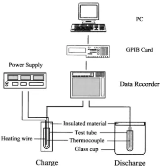
Figure 2 shows the schematic of measuring apparatuses used for obtaining the thermal characteristics of ESM during charge and discharge experiments. The volume of each specimen of ESM in the test tube is 20 cc. The test tube is covered by 1.9 cm thick insulation. Heat input is achieved by connecting the ac power supply to heating wire共resistance heater兲 and is calculated form the product of voltage and current, within approximately 5% error. Each ESM stored energy from the initial temperature of 30° C to the end temperature of 70° C. During heat discharge, the test tube was settle in the glass cup and released heat by natural convection to the surroundings. The initial temperature of each ESM was 70° C for the discharge process, with a final temperature of 30° C. Salt-hydrates, characterized by M . nH2O, where M is an inor-ganic compound, form an important class of heat storage sub-stances due to their high volumetric latent heat storage density.
The major problem in using salt hydrates as ESM is that most of them melt incongruently, i.e., they melt to a saturated aqueous phase and solid phase which is generally a lower hydrate of the same salt. Due to density differences, the solid phase settles out and collects at the bottom of the container. During solidifying, the solid phase does not combine with the saturated solution to form the original salt-hydrate. Another important problem is their poor nucleating properties resulting in supercooling of the liquid salt-hydrate prior to solidification关3兴. Therefore, thickening agents or nucleating agents are generally needed.
It is well-known that paraffin waxes qualify as latent heat phase
Fig. 1 Thermal storage in two-phase thermosyphon solar water heater„a… charge mode, „b…
discharge mode
Fig. 2 Schematic of measuring apparatus used in the ESM
experiments
change materials due to their applicability over large temperature ranges and having high heats of fusion. Paraffin waxes are satu-rated with hydrocarbon mixtures, which normally consist of a mixture of mostly straight chain alkanes, characterized by CnH2n+2. The n-alkane content in paraffin waxes usually exceeds 75% and may reach 100%. The crystallization of the共CH2兲nchain
releases a large amount of the latent heat. Various paraffin waxes with a range of melting temperatures are available. For the solar water heater, the ESM should have a phase change temperature of approximately 40– 60° C. Therefore, tricosane共paraffin wax 116兲 was chosen as the ESM. These substances are nontoxic, noncor-rosive and chemically inert. Furthermore, paraffin waxes present little fire hazard, and they have been used as ESM for thermal energy storage in greenhouses关6兴.
The ESM utilizes sensible heat in the solid and liquid phases and latent heat during phase change. Therefore, the stored heat of the ESM, Qch, may be computed based on sensible heat and latent heat as shown in the following equation:
Qch=
兺
j=0 tb Mcs共Tj+⌬t− Tj兲 + Mhsl+兺
te time Mcl共Tj+⌬t− Tj兲 共1兲During solidifying of the ESM, the released heat of the system, Qdisch, may be computed based on the following equation:
Qdisch=
兺
j=0 tb Mcl共Tj− Tj+⌬t兲 + Mhsl+兺
j=te time Mcs共Tj− Tj+⌬t兲 共2兲Figure 3 illustrates temperature variation of three ESMs during the heat storage process. Due to the different thermo-physical properties of each ESM, the ending time of each ESM in the charge experiment is different. The ending time of sodium acetate is the longest共about 4200 s兲 and the ending time is 3000 s for tricosane and 2500 s for water. It reveals that utilizing sodium acetate as the ESM could store more thermal energy during the same temperature difference. Initially during the charge process, the temperature slope of water is less than others. It is because the specific heat of water is larger and it shows the best performance in the range of sensible heat storage. In the process of latent heat storage, tricosane and sodium acetate show nearly constant tem-peratures during phase change.
Figure 4 indicates temperature variations of the three ESMs during the heat release process. The temperature curves of sodium acetate with and without nucleating agent are also shown. During the heat release process, the initial temperature of each ESM at 70° C produces a liquid state. The temperature of tricosane drops to its solidification temperature, 47° C and solidification occurs at this temperature. However, solidification for sodium acetate does not occur at its phase change temperature, 58° C. It still maintains as a supercooled liquid state. Supercooled liquid refers to a meta-stable state, which will be ended by producing a vibration distur-bance on the tube wall when the temperature is cooled to about 50° C. After applying the slight vibration, nucleation occurs and the thin platelike crystal grows into the supercooled region. Dur-ing the crystal growth process, latent heat released from the crys-tal is consumed by supercooled liquid. At the end of the growth process, the temperature of liquid is returned to its solidification temperature 共58°C兲 and the stored energy is released. Without vibrator disturbance, the meta-stable state exists and remains dur-ing the heat storage process, as shown in the temperature history of sodium acetate without nucleating agent, and the thermal en-ergy can only be released in the form of sensible enen-ergy. This phenomenon is called supercooling and is a serious problem in applying salt-hydrates as the ESM in the heat storage system. In the contrast, the temperature of tricosane drops to its solidification temperature共47°C兲 and solidified without supercooling. It should be noted that the operating temperatures for the discharge
experi-Fig. 3 Temperature variations of each ESM during the heat
storage process
Table 1 Thermo-physical properties of energy storage
materials
Material Tricosane Sodium acetate Water
Molecular formula C23H48 NaCH3COO · 3H2O H2O
Melting point共°C兲 45–47 57–58 0
Heat of fusion共kJ/kg兲a 210 226 333
Density共kg/m3兲a solid 817 1450 917
liquid 786 1280 998
Specific heat共kJ/kg-K兲b liquidsolid 2.892.89 2.791.7 2.094.18
a
Data from关3兴.
b
Data from关3,8兴.
Fig. 4 Temperature variations of each ESM during the heat
ment are fixed 共discharge temperature of each ESM is 70° C to 30° C兲; therefore, the ending time is different. Energy storage material with longer ending time indicates more heat dis-charge. The operating time for tricosane and sodium acetate with nucleating agent is about 3800 s and that of water is about 3100 s, while that for sodium acetate without nucleating agent is 2260 s. Table 2 shows the experimental results of stored heat for tricos-cane, sodium acetate, and water from 30° C to 70° C. In the table, relative index is the ratio of stored heat in ESM to the stored heat in water. The heat capacities of tricosane and sodium acetate are higher than water, which demonstrates that latent heat storage provide better performance than sensible heat storage. Under the conditions of the same storage volume, tricosane and sodium ac-etate can store 57% and 125% more heat than water, respectively. For the case of the same mass, tricosane and sodium acetate have 101% and 75% higher thermal capacities than water, respectively. It is obvious that sodium acetate has the best storage performance among three ESMs. However, supercooling occurs during the so-lidification of sodium acetate, and nucleating agents are needed in order to overcome the problem.
3 Experimental Investigations in the Two-Phase
Ther-mosyphon Solar Water Heater
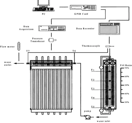
As shown in Fig. 5, the two-phase thermosyphon solar water heater comprises a solar collector, double pipe heat exchanger, fin tubes inside the storage tank, and lower headers. The solar collec-tor consists of ten vertical copper tubes and a heating plate cov-ered by thin foil heaters is used. The storage tank is made of 3 mm thick stainless steel plates. In the storage tank, two rows of fin tubes with 18 fins per inch are mounted. Two headers each are connected at the top and bottom of the storage tank, the two upper headers are copper tubes sealed with copper stoppers on both ends
and contain an internal stainless steel fin tube working as a double pipe heat exchanger during heat discharge. Insulation material at the outside of storage tank prevents heat losses during the experi-ment. The dimensions of the solar water heater are shown in Table 3.
Figure 6 is a schematic of the measuring apparatus used in the experiment for obtaining primarily temperatures and water flow rates. Temperature measurement utilizes T-type thermocouples with 0.3 mm probes and a data recorder. Five points 共T1–T5兲 measure the ESM temperatures; two points共T6 and T7兲 are set at the inlet and outlet of the double pipe heat exchanger to measure the water temperatures. Tricosane, sodium acetate and water are used as the ESM and alcohol is used as the working fluid inside the two-phase thermosyphon, the heat input is 1300 W in the charge process. For heat discharge, the water flow rate is 3 lpm. Both charge and discharge periods are eight hours.
The fill ratio, Vf, expressed by volume percentage, may be
de-fined as follows:
Vf= Vr/Vt⫻ 100% 共3兲
where Vrmeans the actual volume of working fluid, Vtmeans the
total volume of the thermosyphon loop, which was 14,468 ml by measurement. The operating conditions cover fill ratios from 30% to 60%. The liquid level of the working fluids and the correspond-ing temperature measurement points for ESM in storage tank are also shown in Fig. 6.
The charged heat of the system, Qch, may be computed based on the temperature rise of the ESM,⌬Ti,j, as shown in the
follow-ing equation: Qch=
兺
j=0 tb兺
i=15 Mics⌬Ti,j+兺
i=1 5 Mihsl+兺
te 8 hr兺
i=15 Micl⌬Ti,j 共4兲where⌬Ti,j=共Ti,j+⌬t− Ti,j兲. Heat input, Qin, is obtained from the product of electric input power P, and operating time top, which is eight hours.
Qin= P · top 共5兲
The energy calculations for heat discharge include discharged heat, Qdis, and effective heat output, Qeff. The discharged heat may be obtained from the temperature drop of the ESM 共⌬Ti,j兲 as shown in the following equation:
Qdis=
兺
j=0 tb兺
i=1 5 Micl⌬Ti,j+兺
i=1 5 Mihsl+兺
j=te 8 hr兺
i=15 Mics⌬Ti,j 共6兲where⌬Ti,j=共Ti,j− Ti,j+⌬t兲.
The effective heat output, Qeff, indicates the thermal energy actually obtained from the energy discharged, which may be ob-tained from the temperature difference between inlet and outlet of cold water in the double pipe heat exchanger.
Table 2 Experimental results of stored heat for each ESM from
30° C to70° C
Material
Stored heat per unit volume
共kJ/L兲 Relativeindex
Stored heat per unit mass
共kJ/kg兲 Relativeindex
Tricosane 269± 14.5 1.57 345± 18.5 2.01
Sodium acetate 385± 20.5 2.25 301± 15.9 1.75
Water 171± 9.5 1 172± 9.5 1
Fig. 5 Diagram of the two-phase thermosyphon solar water
heater,„1… collector, „2… double pipe heat exchanger, „3… fin
tubes,„4… lower headers, „5… energy storage tank
Table 3 Dimensions of the solar water heater
Component Dimension Unit
Collector
area 0.9 m2
width 1000 mm
Energy storage tank
length 200 mm
height 690 mm
width 960 mm
length of fin tubes 850 mm
diameter of lower header 19 mm
Double pipe heat exchanger
diameter 19 mm
length 970 mm
Qeff=
兺
j=0
8 hr
m˙ c⌬Tj 共7兲
where⌬Tj=共Tout,j− Tin,j兲.
The charge efficiency is the ratio of heat stored in the ESM to heat input from power supply. The discharge efficiency is the ratio of effective absorbed heat from double pipe heat exchanger to heat released from energy storage material.
ch= Qch Qin 共8兲 dis= Qeff Qdis 共9兲
According to the uncertainty analysis proposed by ISO standard 关7兴, the uncertainties of charge and discharge efficiency with 40% fill ratio are obtained. The results for charge efficiency are ±4.49%, ±3.98%, and ±4.68% for tricosane, water, and sodium acetate, respectively. The corresponding results for discharge effi-ciency are ±4.86%, ±3.24%, and ±3.02%
The energy balance equation for the charge process can be ex-pressed as
Qin=
兺
Qch+兺
Ql 共10兲The power input, Qinis equal to the total stored heat,⌺ Qch, and the total heat loss,⌺ Ql. The total stored heat includes the
stored heat in ESM, Qch, the stored heat in system body, QCsb, and the stored heat in working fluid, QCwf. The total heat loss includes
the heat loss from energy storage tank to surroundings, Qloss,t, and the heat loss from heating plate to surroundings, Qloss,p.
The heat loss from the energy storage tank to the surroundings is calculated from the heat loss coefficient of energy storage tank, the area of the system and the temperature difference between the tank and surrounding. The stored heat in system body and the stored heat in working fluid are calculated from the temperature, the mass, and the specific heat of the system components and working fluid. Then Qloss,pcan be obtained from Qinminus Qch, QCsb, and QCwf.
Table 4 shows the experimental results of charge efficiency and heat losses for three different ESMs. As can be seen, the stored heat in the working fluid and in the system body are very small compared with the heat stored in PCM, no matter what kind of ESM is used. The heat losses from heating plate to surroundings are 17.9%, 41.8%, and 15.3% for tricosane, water, and sodium acetate, respectively, which is the dominant component in total heat loss. Note that the charge efficiency with PCM as ESM is higher than water because of their high heat capacities.
Many factors affect the charge or discharge efficiency, such as working fluids; fill ratios, and energy storage materials. These factors make the system operate at different temperatures and thus affect the thermal performance.
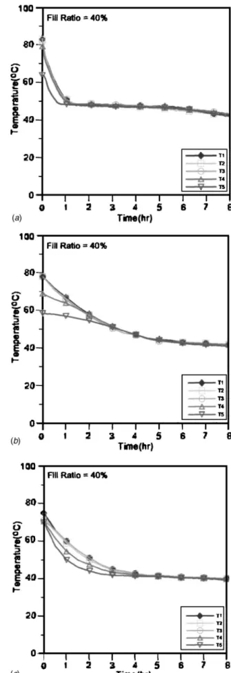
Figures 7共a兲–7共c兲 show temperature variations 共T1–T5兲 of tri-cosane, water and sodium acetate, respectively, during heat
Fig. 6 Schematic of measuring apparatus used in the experiment
Table 4 Charge efficiencies and heat loss percentages
ESM Qloss,t/ Qin Qloss,p/ Qin QCwf/ Qin QCsb/ Qin ch
Tricosane 3.2% 19.6% 1.5% 1.7% 74%
Water 2.8% 47.4% 1.7% 1.1% 47%
Fig. 7 Temperature distributions of „a… tricosane, „b… water, and„c… sodium acetate, during the heat charge process
Fig. 8 Temperature distributions of „a… tricosane, „b… water,
and„c… sodium acetate, during the heat discharge process
charge, for a fill ratio of 40% and heat input of 1300 W. Tricosane and sodium acetate undergo three periods, i.e., solid state, phase change and liquid state, while water remains liquid. Since the fill ratio is 40%, as shown in Fig. 6, the temperature measurement points T1–T3 are above the alcohol level, where is the effective condensation region in the thermosyphon. In this region the ESM has the same temperature profiles and the thermal stratification of ESM does not appear. This is due to the fact that film condensa-tion occurs inside the thermosyphon and keeps the temperature of the ESM uniform. At the region below the alcohol level, the tem-perature profiles of T4 and T5 show serious thermal stratification. In order to reduce the effect of thermal stratification, the fill ratio should be as low as possible in the condenser section. However, the smaller fill ratio will also shorten the effective boiling regions, as the working fluid is boiling in the collector. Therefore there exists an optimum fill ratio, which gives the best charge perfor-mance.
Figures 8 depict temperature variations of tricosane, water, and sodium acetate used as the ESM during the discharge process for the case of 40% fill ratio. Tricosane in Fig. 8共a兲 releases heat to the double pipe heat exchanger and undergoes a phase change period, i.e., the temperature curve is approximately flat in the middle period. In Figs. 8共b兲 and 8共c兲 water and sodium acetate remain in the liquid state and release the sensible heat. Thermal stratification is not serious inside the storage tank. This is due to the fact that different heat transfer mechanisms occur inside the thermosyphon. As shown in Fig. 1, in the region above the alcohol fill level, film evaporation is the dominant heat transfer mecha-nism, while pool boiling appears in the region below the fill level. These two high heat transfer mechanisms destroy the thermal stratification, as the discharged process proceeds. It should be noted that in Fig. 8共c兲 sodium acetate without a nucleating agent is used as the ESM, and the supercooling appears. Supercooled liq-uid exists inside the storage tank and the energy is released by sensible heat. Since the heat capacity of sodium acetate is smaller than water, the temperature profiles drop quicker than those of water during the initial stage of the discharge process.
Figure 9 shows the charge efficiencies under different fill ratios and different ESMs. The system using tricosane as the ESM has an optimum charge efficiency of 73% at 40% alcohol fill ratio. Sodium acetate has an optimum charge efficiency of 81% at
al-most the same fill ratio. While using water as the ESM, the opti-mum charge efficiency is 43%. Figure 10 demonstrates the dis-charge efficiencies under different fill ratios and different ESM. The optimum discharge efficiency for tricosane is 81% at 40% fill ratio. With water and sodium acetate as the ESM, the optimum discharge efficiency is 64% and 20.5%, respectively. Tricosane shows better thermal performance than water for both charge and discharge.
4 Conclusion
Three different energy storage materials are investigated in the two-phase thermosyphon solar water heater. Based on the experi-ments and results just discussed, tricosane qualifies as the best ESM for thermal storage since it has a reasonably high latent heat. Furthermore, it is able to solidify and melt repeatedly and congru-ently. Due to its self-nucleation property, it can be solidified with-out supercooling. In addition, the heat storage efficiency and the heat discharge efficiency using tricosane as the ESM are 30% and 17% higher than with water, respectively. The results also show that an optimum alcohol fill ratio of approximately 40% exists for the optimum performance of the proposed solar water heater, re-gardless of whether the energy storage material is tricosane or water. Using tricosane as the ESM, the optimum heat storage ef-ficiency of the energy storage system is 73% and its optimum heat discharge efficiency is 81%.
Nomenclature
c ⫽ specific heat 共J/kg-K兲 hsl ⫽ heat of fusion 共J/kg兲
M ⫽ mass of ESM 共kg兲 m˙ ⫽ mass flow rate 共kg/s兲 P ⫽ power 共W兲
Qch ⫽ stored 共or charged兲 heat 共J兲 Qeff ⫽ effective heat 共J兲
Qdis ⫽ released 共or discharged兲 heat 共J兲 Qin ⫽ heat input 共J兲
Qloss,t ⫽ heat loss from energy storage tank to the sur-rounding共J兲
Qloss,p ⫽ heat loss from heating plate to the surrounding 共J兲
Fig. 9 Comparison of charge efficiencies under different fill
ratios
Fig. 10 Comparison of discharge efficiencies under different
QCsb ⫽ stored heat in system body 共J兲 QCwf ⫽ stored heat in working fluid 共J兲
Tin ⫽ inlet temperature 共K兲 Tout ⫽ outlet temperature 共K兲
t ⫽ time 共sec兲
tb ⫽ time at the beginning of solidification or melt-ing共sec兲
te ⫽ time at the end of solidification or melting
共sec兲
time ⫽ ending time of experiment 共sec兲 Vr ⫽ volume of working fluid 共ml兲
Vt ⫽ total volume in thermosyphon loop 共ml兲
Greek symbols
⫽ density 共kg/m3兲
Subscripts
i ⫽ level no. of ESM inside storage tank j ⫽ time no. during charge or discharge process l ⫽ liquid state
s ⫽ solid state
References
关1兴 ASHRAE, 1999, Handbook of HVAC Applications, Atlanta, GA, pp. 32.11– 32.14.
关2兴 Mao, C. L., Chun, L. J., Lee, W. S., and Chen, S. L., 2003, “Thermal Perfor-mance of a Two-Phase Thermosyphon Energy Storage System,” Sol. Energy,
75共4兲, pp. 295–306.
关3兴 Abhat, A., 1983, “Low Temperature Latent Thermal Energy Storage: Heat Storage Materials,” Sol. Energy, 30共4兲, pp. 313–332.
关4兴 Esen, M., Durmus, A., and Durmus, A., 1998, “Geometric Design Solar-Aided Latent Heat Store Depending on Various Parameters and Phase Change Mate-rials,” Sol. Energy, 62共1兲, pp. 19–28.
关5兴 Sari, A., and Kaygusuz, K., 2002, “Thermal Performance of a Eutectic Mixture of Lauric and Stearic Acids as PCM Encapsulated in the Annulus of Two Concentric Pipes,” Sol. Energy, 72共6兲, pp. 493–504.
关6兴 He, B., and Setterwall, F., 2002, “Technical Grade Paraffin Waxes as PCMs for Cool Thermal Storage and Cool storage Systems Capital Cost Estimation,” Energy Convers. Manage., 43, pp. 1709–1723.
关7兴 ISO, 1995, Guide to the Expression of Uncertainty in Measurement, Interna-tional Organization for Standardization, Geneva, Switzerland.
关8兴 Wada, T., Yamamoto, R., and Matsuo, Y., 1984, “Heat Storage Capacity Of Sodium Acetate Trihydrate During Thermal Cycling,” Sol. Energy, 33共3–4兲, pp. 373–375.