國 立 交 通 大 學
光電工程研究所
博士論文
可重組態寬頻網路系統之新穎架構
Novel Architectures for Reconfigurable
Broadband Optical Networks
研 究 生 :黃明芳
指導教授:祁 甡 教授
陳智弘 副教授
中華民國 九十六 年 十二 月
可重組態寬頻網路系統之新穎架構
Novel Architectures for Reconfigurable
Broadband Optical Networks
研 究 生 :黃明芳 Student : Ming-Fang Huang
指導教授:祁 甡 Advisors : Sien Chi
陳智弘 Jyehong Chen
國立交通大學 電機學院
光電工程研究所
博士論文
A Dissertation
Submitted in Partial Fulfillment of the Requirements
for the Degree of Doctor of Philosophy in
The Institute of Electro-Optical Engineering
College of Electrical and Computer Engineering
National Chiao Tung University
Hsin-Chu, Taiwan, R.O.C.
中華民國 九十六 年 十二 月
i
可重組態寬頻網路系統之新穎架構
研究生:黃明芳
指導教授:祁 甡
陳智弘
國立交通大學 電機學院
光電工程研究所
摘要
在本篇論文中提出利用光學延遲技術而準確達成新穎無色散的光學交錯器。擁有相 同振幅響應但相反相位響應的一對光學交錯器成功的在模擬與量測結果相符合下實 現,並且使用於雙向波分多工(WDM)傳輸系統當中。此外,將原本設計可用於單 向放大功能的三通道光學交錯器進一步設計成四個通道,以用於雙向波分多工傳輸 架構。在這個研究裡面,深入的探討並實驗論證此四通道光學交錯器在雙向傳輸系 統裡的應用。在網路擷取信號方面,達成 ROADM 以及色散補償光學交錯器之應 用,以解決網路中信號重組的問題;在網路中節省成本的問題下,雙向傳輸系統將 是重要的解決方案,點對點的雙向直線傳輸,高速信號,以及利用迴路的長距離傳 輸都在實驗上成功的實現。也進一步探討不同的調變信號(如 OOK,RZ-DPSK, NRZ-DPSK)與不同放大機制(如摻鉺光纖放大器與半導體光學放大器)在傳輸系 統裡的影響。然而,在不久的將來,WDM-PON 將成為趨勢,在此論文中也更進 一步討論 WDM-PON 的應用,主要分為三個方向:經濟且有效率的雙向傳輸架 構,提供用戶有選擇性的服務以及利用簡單架構同時提供用戶聲音,影像,資料的 三功能服務。實驗結果證實了所提出的方法皆為針對系統缺陷之經濟且有效率的解 決方案,並對於未來光網路的發展有著廣闊的前景。Novel Architectures for Reconfigurable Broadband
Optical Networks
Student: Ming-Fang Huang Advisor: Sien Chi
Jeyhong Chen
Institute of Electro-Optical Engineering
College of Electrical and Computer Engineering
National Chiao Tung University
ABSTRACT
In this dissertation, a novel dispersion-free interleaver using optical delay lines by accurately locating the zeros in the transfer function has been proposed. It has been implemented with the design of interleaver pairs with the same amplitude responses but opposite phase responses for bidirectional DWDM transmission systems. The measured results are consistent with device simulation. The original three-port design using unidirectional amplification has been further modified, and a four-port interleaver has been built and demonstrated to achieve bidirectional DWDM transmission. This investigate fully studied and verified the applications of our four-port interleavers in bidirectional transmission. A re-circulating loop has been setup for metro add/drop applications using an ROADM and dispersion-compensated interleaver pairs to solve the problem of re-configuration. To unravel the fiber shortage issue in metro link, a bidirectional straight-line system, a re-circulating loop and high bit rate transmission had been proposed and experimentally demonstrated. The comparison of different modulation formats, such as OOK, RZ-DPSK and NRZ-DPSK, with different amplification functions, e.g. SOA and EDFA, are also illustrated. Furthermore, WDM-PON is an ultimate solution
iii
for ever increasing bandwidth requirement in the near future. Therefore, a cost-effective bidirectional WDM-PON using novel four-port interleaver, select-cast WDM-PON based on simultaneously generated OOK and DPSK downstream traffic and a simple architecture for WDM-PON to provide triple play services with centralize lightsources have been also established. The experimental results have clearly manifested that the proposed architectures can provide significant improvement on both cost-effective and system reliability.
誌 謝
(ACKNOWLEDGEMENTS)
首先,我要感謝我的指導老師,祁甡老師與陳智弘老師,在這博士班的學習 當中,給了我最好的指導,最大的支持與鼓勵。我也要特別感謝馮開明老師,無論 在清晨或深夜,總是耐心的幫助我解決困惑!感謝賴暎杰老師,李清庭老師,高銘 盛老師以及張宏鈞老師,謝謝你們在我的論文口試中,分享寶貴的意見,讓我得以 更上一層樓。謝謝實驗室的伙伴們:曾弘毅,陳南光,錢鴻章,彭朋群,彭偉仁, 林俊廷,魏嘉建,賴重佑,林擇雨,在實驗室裡的相互鼓勵與協助,使研究之路順 利且充滿歡樂。謝謝光電所裡的好朋友們:黃淑惠,湯宗達,林俊華,徐桂珠,鄭 介任,姚忻宏,陳昭遠,蕭義南,方建舜 等等,在課業及生活上的協助,讓我在 最後的學生生涯中,擁有許多美好的回憶。還有我最窩心的室友們:謝翠如,呂巧 華,楊雅茹,陳彥志跟邱宇捷,謝謝你們的體貼照顧跟陪伴,豐富了我的生命,有 你們在我身邊,真好!I could not be thankful enough for Prof. Gee-Kung Chang who gives me the opportunity to work in Georgia Tech and also a true “friends, philosopher and guide” to me. I would like to express my sincere gratitude toward Dr. Jianjun Yu, for his teaching, advice, help and friendship. I am so proud of to be the member in one of the best research groups in the world, Optical Networking Research Group, and grateful to work with brilliant colleagues, including Dr. Arshad, Harris, Claudio, Zhenseng, Linbing, Chunpeng, Yuting, Feng, and DJ.
最後,我要感謝我的家人,謝謝你們多年來的支持與鼓勵,是你們用無限的 愛與關懷來成就今天的我,謝謝您,我摯愛的爸媽!!
v
TABLE OF CONTENTS
Page CHINESE ABSTRACT i ENGLISH ABSTRA ii ACKNOWLEDGEMENTS iv CONTENTS v LIST OF TABLES ix LIST OF FIGURES x LIST OF ACRONYMS xvLIST OF SYMBOLS xviii
CHAPTER
1 INTRODUCTION 1
1.1. Network Evolution 1
1.2. Motivation 4
1.3. Organization of the Dissertation 7
2 OVERVIEW OF BIDIRECTIONAL SYSTEMS AND INTERLEAVERS 8
2.1. Overview of Bidirectional Systems 8
2.1.1. Bidirectional Interleaved Scheme 9
2.1.2. Bidirectional Amplification Scheme 10
2.2. Overview of Interleavers 11
2.2.1. Michelson–Gires–Tournois Interferometers 13
2.2.2. Fabry-Perot Resonator Arrays 14
2.2.3. Planar Optical Waveguide Interleavers 15
3 DESIGN AND EXPERIMENT OF THE FOUR-PORT INTERLEAVER 17
3.1. Considerations of Interleavers Design 18
3.2. Experimental Results of 100 GHz L-2L-2L Interleavers 21
4 LONG DISTANCE TRANSMISSION BY USING A RE-CIRCULATING
LOOP 25
4.1. Recirculating Loop Test-bed 25
4.2. Add/Drop Applications in Fiber Ring Networks Based on A
Reconfigurable Optical Add/Drop Multiplexer (ROADM) 27
4.2.1. Characteristics of ROADM 28
4.2.2. Periodic Add/Drop Ring Network System 31
4.2.3. Transmission Performances in Ring Network System 32
4.2.4. Summary 35
4.3. Metro Add–Drop Network Applications of Cascaded
Dispersion-Compensated Interleaver 36
4.3.1. Characteristics of Interleaver 36
4.3.2. Experimental Setup and Results 38
4.3.3. Summary 41
5 NOVEL BIDIRECTIONAL TRANSMISSION USING FOUR-PORT
INTERLEAER 43
5.1. Characteristics of Four-Port Interleaver 44
5.2. Straight Line Bidirectional Transmission System 47 5.2.1. System Performances on Straight Line Transmission 48 5.3. Long Distance Transmission Using a Bidirectional Recirculating
Loop 49 5.3.1. System Performances on Loop Transmission 51
5.4. Comparison between Bidirectional DPSK and OOK Signals 52 5.4.1. Bidirectional DPSK Transmission Configuration 53
vii
5.4.2. Results of Bidirectional DPSK Transmission 54 5.5. Bidirectional Transmission 8×40 Gbit/s WDM Signals 56
5.6. Summary 58
6 WAVELENGTH-DIVISION MULTIPLEXING PASSIVE OPTICAL
NETWORKS 59
6.1. General Architecture for WDM-PON 60
6.2. Cost-Effective Bidirectional WDM-PON Architecture 61 6.2.1. Bidirectional WDM-PON Configuration Using Unidirectional
Amplification Scheme 62
6.2.2. Experimental Results 64
6.2.3. Summary 65
6.3. Select-Cast Services in WDM-PON System 66
6.3.1. Principle of Optical Carrier Suppression and Separation 66 6.3.2. Proposed WDM-PON with DPSK and OOK Centralized
Lightwaves 68
6.3.3. Experimental Setup and Results 69
6.3.4. Summary 72
6.4. WDM-PON to Provide Triple Play Services 72
6.4.1. Proposed TPS Scheme in WDM-PON System 73
6.4.2. Experimental Setup and Results 74
6.4.3. Summary 78
7 FUTURE DIRECTIONS 79
7.1. General Architecture for TDM-PON 79
7.2. Novel Hybrid 10G/1G Coexisted TDM-PON 80
7.2.1. Network Architecture and Wavelength Plan 82
7.2.3. 10G TDM-PON using Optical Carrier Suppression and
Separation Scheme 86
7.2.4. Summary 88
7.3. Worldwide Interoperability for Microwave Access (WiMAX) 89 7.4. Mobile WiMAX /Radio over Fiber for Broadband Internet Access in
High-Speed Railway System 89
7.4.1. Proposed Three-Layer ROF Based Transmission System 90 7.4.2. Experimental Configuration and Results for WiMAX/Radio
Over Fiber in High-Speed Train 91
7.4.3. Summary 95 8 CONCLUSIONS 97 8.1. Contributions 98 APPENDIX I 103 REFERENCES 107 VITA 116
ix
LIST OF TABLES
Page Table A.1: Summary of key parameters for the 100 GHz interleaver 105
LIST OF FIGURES
Page
Figure 1.1: Network evolution options. 3
Figure 2.1: Sketch of (a) unidirectional and (b) bidirectional transmission. 8 Figure 2.2: Wavelength interleaved scheme. (a) Separate bands, (b) interleaved channels,
and (c) same wavelength using circulators. 10
Figure 2.3: Bidirectional amplification scheme. 11
Figure 2.4: Illustration of the function of an (a) optical interleaver and (b)
de-interleaver. 12 Figure 2.5: Different types of interleavers. (a) Seperation of channels out to 1:4, and (b)
seperates even and odd bands of channels. 13
Figure 2.6: A Michelson–Gires–Tournois interferometer filter. 14 Figure 2.7: An Interleaver based on Fabry–Perot resonator arrays. 14 Figure 2.8: Electro-optically tunable lithium niobate (LiNbO3) interleaver. 15
Figure 2.9: Lattice filters unit cell. 16
Figure 3.1: Possible configuration of a three-port L-2L interleaver. 19 Figure 3.2: Measurement setup of birefringent crystal temperature sensitivity
interleaver. 20 Figure 3.3: Two types of interleavers with same amplitude but opposite delay
response. 21 Figure 3.4: (a) Re-centered transmission at 0 °C, 23 °C and 65 °C. (b) Magnified
Folded transmission at 0 °C, 23 °C and 65 °C. (c) 0.5 dB passband at 0 °C, 23 °C and 65 °C. (d) Polarization dependent loss 0 °C, 23 °C
and 65 °C. 22
Figure 3.5: (a), (b): Measured re-centered amplitude of Mux and Demux; (c), (d)
measured re-centered delay of Mux and DeMux. 23
Figure 3.6: Measured cascaded delay response for different frequency. 24 Figure 4.1: Phase of a recirculating loop. (a) Filling the loop, (b) circulating, and
xi
Figure 4.2: Timing diagram of the recirculating loop. 27
Figure 4.3: The mask of the ROADM. 28
Figure 4.4: (a) Schematic diagram of the ROADM, (b) crossbar switch of the ROADM, and (c) optical spectra obtained at drop port and main
output port when one channel is dropped. 29
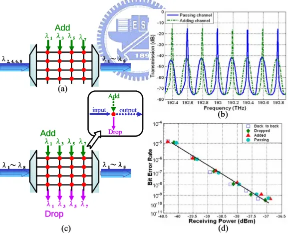
Figure 4.5: (a) Schematic diagram of simultaneous addition of odd channels and passing through of even channels at the ROADM, (b) optical spectra for passing (even) and adding (odd) channels, (c) schematic diagram for eight passing and four adding/dropping channels, and (d) the BER
curves for these channels in (c). 30
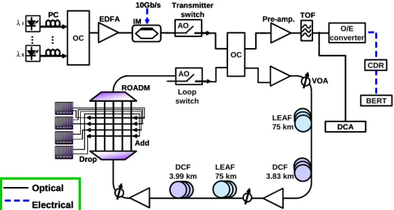
Figure 4.6: Experimental configuration of a recirculating loop based periodic
add/drop ring network. 32
Figure 4.7: Power penalty variation at BER = 10-9, with ±11 GHz frequency detuning, for cascading the ROADM for one, four and seven times. 33 Figure 4.8: (a) Optical spectrum and receiving sensitivity for eight channels, and
BER curves and corresponding eye diagrams at channel three for (b) pass-through function after 1050 km of transmission and (c) periodically added/dropped signals at every 150 km. 34 Figure 4.9: (a) Two operation connections for a four-port interleaver; (b) In-band
group delays for two types of interleaver connection; (c) group delays of compensated and uncompensated interleaver-pair connections, and (d) group delays of two cases after five cascaded interleaver pairs. 37 Figure 4.10: Experimental setup for metro add/drop applications. 39 Figure 4.11: Receiving sensitivity variation. (a) compensated and uncompensated
cases after five cascaded interleaver pairs, and (b) compensated and uncompensated configuration with ± 10 GHz wavelength detuning at
BER = 10−9. 40
Figure 4.12: BER curves and corresponding eye diagrams at channel five when wavelength is detuned for ± 8 GHz (a) without compensation and (b)
with compensation. 41
Figure 5.1: (a) Picture of the four-port interleaver; (b) Detail configuration of
four-port L-2L interleaver. 44
Figure 5.3: Transmission Spectrum of a four-port interleaver: (a) the whole C-band, (b) 2-nm wavelength range, and (c) illustration of working
principle of a four-port interleaver. 46
Figure 5.4: Experimental setup of a straight line bidirectional transmission system 47 Figure 5.5: (a) BER curves and corresponding eye diagrams of the worse channel for
unidirectional and bidirectional transmission. (b) Power penalty of bidirectional and unidirectional transmission and received optical spectrum
for east-even channels after 210 km bidirectional transmission. 48 Figure 5.6: The recirculating loop setup for long distance bidirectional
transmission experiment. 50
Figure 5.7: (a) Received optical spectrum; (b) received power penalties at BER equals to 10-9 of all channels after 500 km; (c) BER curves and corresponding eye diagrams at channel seven after transmission, and (d) accumulated errors measured as a function of time. 52 Figure 5.8: Bidirectional DPSK transmission experimental setup. 53 Figure 5.9: BER curves and corresponding eye diagrams of (a) RZ-DKSP at channel 1,
4, and 8, (b) comparison of RZ and NRZ-DPSK at channel 4, and (c) received power penalties for all channels for bi- and unidirectional transmission at BER = 10-9 and output optical spectrum of bidirectional
RZ-DPSK transmission after 230 km for even channels. 54
Figure 5.10: BER curves and corresponding eye diagrams after 80 km
transmission by using a SOA as inline amplifier. 56
Figure 5.11: (a) BER curves and corresponding eye diagrams of Back-to-Back, ch1, ch4 and ch8 without transmission fiber and DCF; (b) received penalties at a BER
of 10-9 of all channels. 57
Figure 6.1: Ideal for broadband access network Experimental results. 59
Figure 6.2: General architecture for a WDM-PON. 61
Figure 6.3: Proposed bidirectional WDM-PON system. 62
Figure 6.4: Experimental configuration for bidirectional WDM-PON system. 63 Figure 6.5: Received optical spectrum of (a) 8-upstream, and (b) 8-downstream
signals after 100 km SSMF. 64
Figure 6.6: (a) BER curves at upstream 1, 6 and downstream 3, 8. Inset: Received eye diagrams. (b) Power penalties at BER = 10-9 of all channels with bi-directional transmission, upstream data only and downstream
xiii
Figure 6.7: Principle of optical carrier suppression scheme. (a) experimental setup to generate OCSS technique; (b) the biased point of the modulator; (c) output optical pulse ; (d) optical spectrum after OCS with 5 GHz RF. 67 Figure 6.8: Proposed novel WDM-PON architecture with DPSK and OOK
centralized lightwaves. 69
Figure 6.9: Experimental setup with centralized lightwaves in WDM-PON. 70 Figure 6.10: Received optical spectra (RB = 0.01 nm). (a) After DAM showing 8
channels as inset (i) in Fig. 6.9; (b) After IM and PM as inset (ii) in
Figure 6.9. 71
Figure 6.11: Measured BER curves and the corresponding eye diagrams. (a) Downstream B-T-B and after 20-km transmission for OOK and
DPSK; (b) Upstream B-T-B and after 20 km SMF. 71
Figure 6.12: Proposed simple WDM-PON architecture simultaneously provides
triple-play service. 73
Figure 6.13: Experimental configuration for WDM-PON network. 75 Figure 6.14: Received optical spectrum (RB = 0.01nm). (a) after intensity
modulator showing 4 channels as inset (i) in Figure 6.13; (b) one of the four modulated signal; (c) separated optical carrier and (d) separated SCM signals as inset (ii) and (iii) in Figure 6.13. 76 Figure 6.15: Measured BER curves and the corresponding eye diagrams.
(a) Downstream B-T-B and after 20 km transmission for 10 Gb/s baseband data and 2.5 Gb/s sub-carrier signals, and (b) 2.5 Gb/s upstream data B-T-B and transmission over 20km SMF-28 fiber. 77
Figure 7.1: General architecture of TDM-PON. 79
Figure 7.2: Proposed hybrid 10G/1G coexisted TDM-PON architecture using
reflective ONUs. General architecture of TDM-PON. 83
Figure 7.3: Wavelength plans for (a) traditional EPON/GPON and (b) proposed
hybrid 10G/1G coexisted TDM-PON reflective ONUs. 84
Figure 7.4: Experimental setup for TDM-PON. 85
Figure 7.5: Received optical spectra: (a) combined downsream signal and four CW sources as inset (i) in Figure 7.4; (b) upstream signal over 20-km
SSMF as inset (ii) in Figure 7.4. 85
Figure 7.6: BER curves and corresponding eye diagrams: (a) upstream and (b) downstream with B-T-B and over 20 km transmission. 86
Figure 7.7: Experimental setup for TDM-PON using OCSS scheme. 87 Figure 7.8: Received optical spectra: (a) one of four CW sources after OCS. As
inset (i) in Figure 7.6. (b) combined downstream signal and four CW sources over 20 km SSMF as inset (ii) in Figure 7.6. 88 Figure 7.9: Proposed three-layer ROF based transmission system. 91 Figure 7.10: Experimental setup of the proposed WiMAX/radio over fiber for
high-speed train. 92
Figure 7.11: Optical spectrum. (a) λ1 with 5.5 GHz RF clock as inset (i), (b) λ2
with 5.8 GHz RF clock as inset (ii), (c) combined signals after IM as inset (iii), (d) after interleaver as inset (iv), (e) re-modulated signal
after 400-m SSMF as inset (v) in Figure 7.9. 93
Figure 7.12: Optical eye diagrams at different locations labeled in Figure 7.9. 94 Figure 7.13: BER measurements at railroad distribution RoF system (20-km SMF)
and intra-train RoF (400-m SMF). 95
Figure A1.1: Measurement and simulation results of center frequency offset due
to dispersion. 106
xv
LIST OF ACRONYMS
ADSL asymmetric digital subscriber lineASE amplified spontaneous emission
ATM asynchronous transfer mode
AO acousto-optic
AWG array waveguide grating
BPON broadband PON
BS band separators
CBR constant-bit-rate
CDR clock and data recovery
CO central office
DAM dual-arm modulator
DBA dynamic bandwidth allocation
DCF dispersion compensated fiber
DFB distributed feedback
DPSK differential phase-shift keying
DQPSK differential quaternary phase shift keying
DSL digital subscriber line
DWDM dense wavelength-division-multiplexing
DXC digital cross-connects
EDFA erbium-doped fiber amplifier
EO electro-optical
EPON Ethernet PON
FEC forward error correction
FP Fabry-Perot FTTB fiber-to-the-building FTTH fiber-to-the-home
GPON Gigabit PON
GTI Gires-Tournois interferometer
GTR Gires-Tournois resonator
HDTV high-definition TV
HFC hybrid fiber-coax
HWP half-wave plates
IP Internet protocol
ITU International Telecommunication Union
IL Interleaver
LO local oscillator
LOA linear optical amplifier
MAN metro area networks
MCA media access controller
MI Michelson interferometer
MZ-DI Mach-Zehnder delay-line
NF noise figure
NRZ-DPSK non-return-to-zero differential phase-shift keying OCSS optical carrier suppression and separation
OLT optical line terminal
ONU optical network unit
OOK ON-OFF keying
OSA optical spectrum analyzer
OSNR optical signal to noise ratio
PBS polarization beam splitter
PBS proxy base stations
PC polarization controller
PDG polarization dependent gain
PDL polarization dependent loss
PLC Plana r lightwave circuit
PM phase modulator
PON passive optical networks
PRBS pseudo random binary sequence
QoS quality of service
QPS quadruple play services
RB Rayleigh backscattering
RDCC Railway WiMAX/RoF Distribution and Control Center
ROADM reconfigurable optical add/drop multiplexer
ROF radio over fiber
RSOA reflective semiconductor optical amplifier RZ-DPSK return-to-zero differential phase-shift keying
SCM sub-carriers multiplexing
SDH synchronous digital hierarchy
SOA semiconductor optical amplifier
SSMF standard single-mode fibers
TDM-PON time-division-multiplexing passive optical networks
TAP train access point
xvii
VDSL very high speed digital subscriber line WDM wavelength division multiplexing
WDM-PON wavelength division multiplexing passive optical network
WiFi wireless fidelity
WiMax World interoperability for microwave access
XGM cross-gain modulation
LIST OF SYMBOLS
∆n group index difference between ordinary and extraordinary axes
c speed of light
FSR free spectral range
L length of the crystal
λcenter center wavelength of the operation wavelength range
m the order of the birefringent wave plate
β normalized variation in the wavelength with temperature )
( ˆ fn
x target amplitude response
) (fn
x real transmission function
1
CHAPTER 1
INTRODUCTION
1.1 Network Evolution
Over the past few years, the evolution of the Internet has proved that wavelength-division multiplexed (WDM) is the most flexible and robust solution for the present and future dynamic network traffic. As the Internet transitions from a best-effort network to a strategic global Internet protocol (IP) infrastructure, demands will not only be for higher bandwidth, but also for a wider range of integrated services demanding high reliability [1–5]. The broadband access network connects the service provider at a central office (CO) to the subscribers, which include businesses and homes. Recently, subscribers have been demanding high bandwidth services such as video-on-demand and high-speed internet for both downloading and uploading information. Current access technologies such as hybrid fiber-coax (HFC), digital subscriber line (DSL), and wireless networks have severe limitations in transporting symmetric traffic or high bandwidth information. However, the nature of the traffic that is sent through the Internet is changing. New applications require higher bandwidths, support for constant-bit-rate (CBR) streaming media, symmetric data rates for peer-to-peer file transfer, low delay for interactive applications and security. The internet will need many architectural upgrades to accommodate these new demands. The common used methods are included:
1) IP — the Internet Protocol. It started life as protocol which was used for communication over the Internet. IP was optimized for data service and was packet
based, rather than circuit switched and also well suited to streamed audio and video broadcast.
2) ATM— Asynchronous Transfer Mode. It was probably the first serious contender for providing broadband multi-service network. ATM is a packet based system, using fixed length packets, and is designed to support a wide range of services such as voice, video and frame relay.
3) ADSL— Asymmetric Digital Subscriber Line. It was first developed to enable a broadband always-on connection to be provided over a copper pair. ADSL is asymmetric and supplies a greater downstream capacity than the upstream, typically of 1.5 Mbps downstream and 128 Kbps upstream bandwidth.
4) VDSL— Very high speed Digital Subscriber Line. An increased downstream of 50 Mbps can be achieved using VDSL, but this comes at the expense of shorter distance, typically less than 1500 ft (457.2 km).
5) PON — Passive Optical Network. It provides fiber communications without expensive electronics. PON are well studied to enhancing existing networks by replacing the copper between the local exchange and a flexibility point.
6) HFC— Hybrid-fiber Coax. HFC systems substitute most of co-axial cable between the cable TV head-end and the customer with fiber. It is used to transmit both broadcast video and high-speed data services.
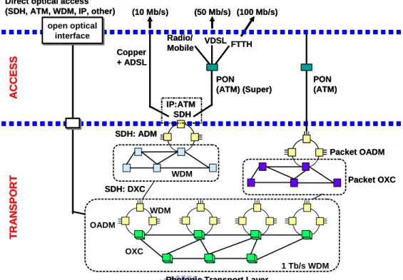
Figure 1.1 shows the possible evolution skeleton for the network. On the access side, the first evolution will include the development of optical fiber in the feeder network that close to the customer by ADSL technology, allowing the last relatively short copper. Similarly, the fiber in HFC networks will come closer to the customer, serving the small
3
number of businesses and homes with the coax tree. This will support bit rate up to 10 Mbps downstream and meet the capacity requirement of small offices and homes. The copper based access, such as VDSL technology that support up to 50 Mbps downstream bandwidth, will gradually migrate to fiber access. The fiber link can be based on passive optical network technology (PON) and SuperPON using optical amplifiers. Ultimately, the bandwidth of 100 Mbps per subscriber will meet the demands of fiber-to-the-home (FTTH).
The transport network supports the accumulated traffic generated in the access network and the link capacities on the order of 1 Tbps will be necessary in the near future. Currently, many networks are progressing to synchronous digital hierarchy (SDH) architecture, with a transport comprising a mesh of digital cross-connects (DXCs)
From: J. Aarnio, Nokia Research Center, 2002 Figure 1.1: Network evolution options.
Photonic Transport Layer
A CCE SS A CCE SS TR A NSPORT TR A N SP O R T OXC OADM 1 Tb/s WDM IP:ATM SDH FTTH VDSL Radio/ Mobile PON (ATM) (Super) (100 Mb/s) (50 Mb/s) Copper + ADSL (10 Mb/s) WDM SDH: DXC SDH: ADM Packet OXC PON (ATM) Packet OADM Direct optical access
(SDH, ATM, WDM, IP, other)
WDM open optical
interface open optical
interface
Photonic Transport Layer
A CCE SS A CCE SS TR A NSPORT TR A N SP O R T OXC OADM 1 Tb/s WDM IP:ATM SDH FTTH VDSL Radio/ Mobile PON (ATM) (Super) (100 Mb/s) (50 Mb/s) Copper + ADSL (10 Mb/s) WDM SDH: DXC SDH: ADM Packet OXC PON (ATM) Packet OADM Direct optical access
(SDH, ATM, WDM, IP, other)
WDM open optical
interface open optical
interconnecting rings. Fiber link in the long-haul networks is currently being upgraded to use WDM technique, which has similar functions to the electrical SDH network. The optical transport layer is a key evolutionary development because of its effectively transparent to bit rate and signal format. Furthermore, it also can support different types of access, such as WDM, IP and so on. Unlike HFC and DSL technologies, wireless networks such as wireless fidelity (WiFi) and world interoperability for microwave access (WiMax) do not require any optical fiber or cable for the transmission of information from the central office to the subscribers. Wireless networks allow users to be mobile but have limited bandwidth and security issues.
1.2 Motivation
Next generation broadband optical network will likely require a considerable increase in total spectral efficiency. The emergency of broadband communications has increased the need for bulk transport of high capacity signals and services. Optical WDM networks have been widely recognized as the dominant transport infrastructure for future Internet backbone networks with its potential of providing virtually unlimited bandwidth [5]. The reconfigurability of WDM networks has the following features: the network’s configuration can be increased by bypassing, adding or dropping the traffic and the capacity throughput enlarges when the traffic is multiplexed on the fiber by WDM. However, in metro area networks (MAN) that encounter fiber shortages problem, bidirectional transmission is an appealing means of increasing the bandwidth utilization in a single optical fiber and, at the same time, reducing the operation and maintenance cost[6–8]. One of the core technologies in bidirectional transmission system is realizing
5
of bidirectional amplification, which typically requires high gain, low noise and the elimination of Rayleigh backscattering (RB) [9]. One of the efficient methods in bidirectional transmission is using wavelength interleaving scheme. As an optical filter, an interleaver combines or separates a comb of dense wavelength-division multiplexed (DWDM) signals [10–12]. Although interleaver has been widely used in multiplexing and demultiplexing of DWDM optical signals, its applications in bidirectional transmissions have not been fully studied and verified. As a result, the motivation of this dissertation lies in the investigation of a reliable solution for bidirectional transmission in WDM network by using a new designed four-port interleaver.
Among several choices of modulation and demodulation formats in optical access networks, ON-OFF keying (OOK) format [13, 14] is the most popular for its simple generation. Recently, special attention has been given to differential phase-shift keying (DPSK), which was proving to be superior [15] relative to the traditional OOK in optical fiber communication system. This is due to its larger tolerance to fiber nonlinearity and noise from amplified spontaneous emission (ASE). The phenomenon of different modulation formats, such as OOK, return-to-zero DPSK (RZ-DPSK) and non-return-to-zero DPSK (NRZ-DPSK) with dissimilar amplification schemes, i.e. erbium-doped fiber amplifier (EDFA) and semiconductor optical amplifier (SOA) in bidirectional transmission systems would be investigated.
Since the downstream data is shared among several subscribers in HFC systems, the available bandwidth per user depends on the number of subscribers connected to the internet. Additionally, the upstream bandwidth is limited because of ingress noise generated from appliances at the subscribers end. Therefore, highly efficient, next
generation, broadband optical networks providing symmetric upstream and downstream information would be difficult to develop using HFC and DSL infrastructures. However, PON technology is a considered an ultimate solution. Network carriers have begun to deploy time-division-multiplexing passive optical networks (TDM-PONs) such as broadband PON (BPON), Ethernet PON (EPON) and Gigabit PON (GPON) and wavelength-division multiplexing passive optical networks (WDM-PON) in response to the current trend of data- and image-based services resulting from the rapid growth of all kinds of multimedia Internet applications. In addition, WDM-PON is a promising approach for gigabit optical access network [16].
How to reduce the cost is always the most important issue in WDM-PON system. The first subject of WDM-PON is to design and implement a cost-effective scheme for bidirectional WDM-PON using the four-port interleaver. The second subject is to design a new method to provide select-cast services in WDM-PON system. The proposed WDM-PON has been implemented using optical carrier suppression and separation (OCSS) technology to generate a wavelength pair from a single laser source at the central office and deliver downstream signals in different modulation formats, i.e. OOK and DPSK. This method enables the co-location of both upstream and downstream WDM transmission in the central office. Additionally, the complexity, cost and maintenance of the optical network unit are reduced by enabling wavelength-independent operation. Since radio/mobile access is continuously growing and placing increasing demands on the network. The third subject is to devise a simple and cost-effective configuration in WDM-PON to supply triple play service (TPS). Only one single-arm intensity modulator is needed in this proposed scheme to provide significant improvement on both power
7 budget and system reliability.
1.3 Organization of the Dissertation
In Chapter I,a brief introduction of WDM networks and the motivation to overcome the limitation in bidirectional WDM transmission in different modulation formats are introduced. In Chapter II, an overview of bidirectional transmission system and the technique of the interleaver are studied. Four different types of interleaver by using Michelson-Gires-Tournois interferometers, Fabry-Perot resonator arrays, planar optical waveguides, and Lattice Filters are prsented, respectively. In Chapter III, the design, simulation and experiment of the four-port interleaver is illustrated.
In Chapter IV,a re-circulating loop to simulate long distance transmission has been introduced and experimentally demonstrated. Two experiments, using reconfigurable optical add/drop multiplexer (ROADM) and cascaded dispersion-compensated interleaver, are demonstrated. Novel bidirectional transmission using four-port interleaver to enable unidirectional amplification scheme is presented in Chapter V. The characteristics of the four-port interleaver and three experiments are shown in this chapter: straight-line bidirectional transmission, long-distance transmission using a re-circulating loop, comparison between bidirectional DPSK and OOK signals, and high bit rate transmission. New bidirectional WDM-PON, select-cast services in WDM-PON and triple-play services WDM-PON configuration are discussed and realized in Chapter VI. The future work will be presented in Chapter VII as novel hybrid 10G/1G coexisted TDM-PON andmobile WiMAX /Radio over fiber for broadband Internet access in high-speed railway system. Finally, the conclusions are summarized in Chapter VIII.
CHAPTER 2
OVERVIEW OF BIDIRECTIONAL SYSTEMS AND INTERLEAVER
2.1 Overview of Bidirectional Systems
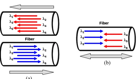
For any multispan DWDM system, optical components such as transmission fiber and optical amplifiers represent substantial cost. In the past few years, the traditional unidirectional transmission, as shown in Figure 2.1(a), had been realized in the market. Nonetheless, more network links are needed for different directional transmission. However, bidirectional transmission has many obvious advantages over unidirectional transmission. Bidirectional transmission through one fiber, shown in Figure 2.1(b), is an attractive method for simultaneously reducing operating and maintenance costs by sharing the optical transmission fiber and the inline amplifiers [9, 17]. In addition, it can increase the spectral efficiencies of the conventional unidirectional WDM transmission system [18]. λ1 λ2 λ3 λ4 λ5 λ6 λ1 λ3 λ5 λ2 λ4 λ6 λ1 λ3 λ5 λ2 λ4 λ6 Fiber Fiber λ1 λ2 λ3 λ4 λ5 λ6 λ1 λ3 λ5 λ2 λ4 λ6 λ1 λ3 λ5 λ2 λ4 λ6 Fiber Fiber
Figure 2.1: Sketch of (a) unidirectional and (b) bidirectional transmission (a)
9
Possible approaches for bidirectional amplification are band splitting or channel interleaving [6, 8, 19], the use of arrayed waveguide gratings (AWGs), Mach-Zehnder WDM coupling, the use of circulators or the use of a gain-clamping semiconductor optical amplifier (SOA), called a linear optical amplifier (LOA) [9]. However, these approaches require the use of two or more EDFAs to achieve bidirectional transmission.
2.1.1 Bidirectional interleaved scheme
Basically, the counter-propagating signals on the same transmission fiber using suitable components are presented in Figure 2.2 [20]. Figure 2.2(a) shows the first approach for band separation by using band separators (BS). The transmitted signals are divided in two groups as red-band and blue-band, traveling in opposite directions. Bands are separated and combined by optical devices inserted in line along transmission medium. In order to prevent the adjacent bands from opposite direction, a band gap is needed between two bands. Figure 2.2(b) displays the second method to achieve bidirectional transmission and alleviates the band separation problem by using two interleavers (IL) to interleave channels in the two directions of transmission. This means that even channels will travel east to west, whereas odd channels will travel west to east. As the consequence, channel spacing for wavelength traveling in the same direction has to be doubled. There is another scheme to transmit the same wavelength in both directions, as Figure 2.2(c). Optical circulators (Cir) are used to separate transmitted eastbound and westbound traffic. However, in these technologies, traffic from each direction is then individually amplified using a corresponding erbium-doped fiber amplifier (EDFA). The gain of EDFAs are typically limited to avoid the RB
self-oscillation [21, 22], these limitations will significantly shorten the amplification span and reduce optical signal to noise ratio (OSNR) [23], thus increase the operational cost and degrade the transmission quality. One of the important issues in bidirectional transmission system is RB. In this wavelength interleaving scheme, the RB induced from eastbound traffic would be amplified in eastbound direction. Therefore, the performance of bidirectional transmission is severely impaired by this kind of nonlinearity. Furthermore, this scheme needs more optical components and more EDFAs; therefore, it is not a cost-effective solution.
2.1.2 Bidirectional amplification scheme
Another approach scheme is using bidirectional amplification as shown in Figure 2.3. Figure 2.2: Wavelength interleaved scheme. (a) Separate bands, (b) interleaved channels, and (c) same wavelength using circulators.
From: Cisco Systems, Inc. White Paper, 2001. (a) (b) (c) Cir Blue-band Red-band BS IL EDFA Cir Cir Blue-band Red-band BS IL EDFA
11
Two amplifiers in opposite direction [24], one inline amplifier, LOA [9], and one SOA [10] had been proposed and published. The first manner can not use any isolator within amplification section; therefore, the RB would be amplified and impaired the quality of the networks. In Ref. [9], the characteristics of the gain-clamping effect limit the gain of LOA to less than 20 dB and a high noise figure (NF) is inevitable. Although SOA can simplify the bidirectional transmission, it needs to be operated above the saturation level to obtain the required optical signal-to-noise ratio (OSNR) at the receiver. The waveform distortion and cross-gain modulation (XGM) poses severe challenges to operate SOAs in the saturation region.
2.2 Overview of Interleavers
In an optical communication system using WDM, information is transmitted over several channels, each at different optical wavelength or optical carrier frequency. An interleaver is an optical filter having at least one input port and two complementary output ports, with an optical transfer functions that is periodic in frequency. In this way, even-numbered channels can be routed to one output port while the odd-channels will merge from the other output port, as depicted inFigure 2.4(a). Meanwhile, the device can be used in a reverse direction that combines two sets of DWDM channels (odd and even channels) into a composite signal stream in an interleaving way [13–15] as shown in
From: IEEE PTL., Vol. 16, No. 4, pp. 1194–1196, 2004. Figure 2.3: Bidirectional amplification scheme
Figure 2.4(b). There are different types of interleavers exhibited in Figure 2.5[11]. The original 1:2 design is presented in Figure 2.4. The periodic separation of one in every 2N
input wavelengths is achieved using the 1:4 interleaver is shown in Figure 2.5(a). The last interleaver design (4:8) used to separate a band of even and odd wavelengths is indicated in Figure 2.5(b). Commercial interleavers are available separating DWDM combs with channel spacing of 25 GHz, 50 GHz, 100 GHz and 200 GHz. The period of the interelaver is determined by the FSR of the components used to make the device. As stated before, interleavers can be built from any type of wavelength filter having a periodic frequency response. In principle, any optical (de)multiplexer having a periodic response with frequency may be used as an interleaver. Currently, there are some approaches to building optical interleaver based on different operating principles and using different technologies: 1) Michelson-Gires-Tournois interferometers [28, 29], 2) Fabry-Perot resonator arrays [30], 3) planar optical waveguide interleavers [31], 4) Lattice Filters [32]and so on.
Figure 2.4: Illustration of the function of an (a) optical interleaver and (b) de-interleaver
Int e rl ea v e r 8 1
λ
λ
L
L
L
L
1 3 5 7λ
λ
λ
λ
Odd 8 6 4 2λ
λ
λ
λ
Even In te rl ea v e r 8 1λ
λ
L
L
L
L
7 5 3 1λ
λ
λ
λ
Odd 8 6 4 2λ
λ
λ
λ
Even Int e rl ea v e r 8 1λ
λ
L
L
L
L
1 3 5 7λ
λ
λ
λ
Odd 8 6 4 2λ
λ
λ
λ
Even In te rl ea v e r 8 1λ
λ
1L
L
L
L
λ
8λ
L
L
L
L
7 5 3 1λ
λ
λ
λ
Odd 8 6 4 2λ
λ
λ
λ
Even (a) (b)13
2.2.1 Michelson–Gires–Tournois Interferometers
The Michelson interferometer (MI) is the bulk equivalent of the Mach-Zender interferometer with a ring resonator coupled to one of its branches. It operates on the periodic of a Gires-Tournois interferometer (GTI). One or two mirrors of the MI are replaced by a Gires–Tournois resonator (GTR), a Fabry-Perot (FP) resonator with 100% mirror and can be used in reflection, so-called a Michelson-Gires-Tournois interferometer as displayed in Figure 2.6. Michelson-Gires-Tournois interferometers operate on the phase return from the two Michelson arms. Although one of the interleaver output signals will be back reflected, it can be separated from the input signals by tilting some of the mirrors. The back reflected light has a frequency response that is complementary to that of the transmitted light, and the input signal will appear frequency interleaved at the reflection and transmission port of the device.
Figure 2.5: Different types of interleavers. (a) Seperation of channels out to 1:4, and (b) seperates even and odd bands of channels.
(a) (b) In te rl eav e r 8 1
λ
λ
LLLL In te rle a v e r 8 1λ
λ
LLLL λ1 λ5 λ1…….λ4 λ5…….λ8 In te rl eav e r 8 1λ
λ
LLLL In te rle a v e r 8 1λ
λ
LLLL In te rle a v e r 8 1λ
λ
LLLL λ1 λ5 λ1…….λ4 λ5…….λ8
2.2.2 Fabry-Perot resonator arrays
Figure 2.7 illustrates the interleaver based on Fabry-Perot resonator arrays, a resonant cavity formed by two parallel reflecting mirrors separated by a medium, using a circulator for separating input and reflected output light. By arranging a number of resonators, while choosing the mirror reflectance carefully, the rectangular-shaped transfer function that is desirable for interleaver operation can be well approximated. Output 1 and output 2 are complementary that can produce frequency-interleaved signals.
Figure 2.6: A Michelson–Gires–Tournois interferometer filter.
BS Gires-Tournois Etalon Output port 1 Output port 1 Output port 2 Output port 2 mirror Light in BS Gires-Tournois Etalon Output port 1 Output port 1 Output port 2 Output port 2 mirror Light in Light in Output port 2 Output port 2 Output port 1 Output port 1 R1 R2 RN
Array of equally spaced mirrors Light in Output port 2 Output port 2 Output port 1 Output port 1 R1 R2 RN
Array of equally spaced mirrors
Figure 2.7: An Interleaver based on Fabry–Perot resonator arrays.
15 2.2.3 Planar Optical Waveguide Interleavers
Most of works on interleaver filters in planar technology have been done in silica-based waveguide systems by AT&T/Lucent [32], NTT [33], and others [34]. Polymers also can be used as the material because of their simple processing and hence possibly lower cost. However, this kind of material may have problems with long-term stability. Lithium niobate (LiNbO3) is an attractive material because of its electro-optic properties
and mature technology. Filters fabricated in this technology are often based on frequency-selective mode conversion. Electro-optically tunable interleaver based on this principle is shown in Figure 2.8 [30]. The strain-inducing strips produce an off-diagonal element in the refractive index tensor leading to different polarization mode conversion. The frequency at which the phase matching condition for efficient mode conversion is tuned by a voltage on the electrodes, changing the birefringence of the lithium niobate crystal.
2.2.4 Lattice filters
Basically, lattice filters are made from many cascaded differential-delay elements
From: J. Lightwave Technology, 21, pp. 837-847, 2003
Light in Output port 1 Output port 1 Output port 2 Output port 2 waveguide Tuning electrodes Strain-inducing strips Light in Output port 1 Output port 1 Output port 2 Output port 2 waveguide Tuning electrodes Strain-inducing strips
where one polarization is delayed along the slow axes of the crystal and the other polarization is not. The differential-delay of each element is an integral multiple of a unit delay and power is exchanged across paths between the elements. It is a huge topic in lattice filters and not limit to optical domain. Figure 2.9 only illustrated a simple and basic block structure of a lattice filter. Within the lattice filters, there is the birefrignent filters that adapted polarization insensitivity through polarization diversity. A polarization diversity scheme separates the input light into two orthogonally polarized rays. They take turns to pass through the waveplate cascaded. After that, the polarizations are re-combined onto two output ports. Consequently, the light that clipped by the output polarizer of the canonical birefringece filter is instead redirected to a complimentary port. In this dissertation, the design of our interleavers is based on the principles of lattice filter.
Figure 2.9: Lattice filters unit cell.
2L
1L
Delay line
Delay line OutputOutput
input input PBS
2L
1L
Delay lineDelay line OutputOutput
input
input
17
CHAPTER 3
DESIGN AND EXPERIMENT OF THE FOUR-PORT
INTERLEAVER
As an optical filter, an interleaver combines or separates a comb of dense wavelength-division multiplexed (DWDM) signals. The periodic nature of the interleaver filter reduces the number of Fourier components required for a flat passband and a high-isolation rejection band. This behavior is great contrasts to the single-channel add/drop filters that synthesize a single narrow-band filter over a wide rejection band.Because the interleaver requires fewer Fourier components than a single narrow band filter, the same flat top, sharp edge response of a higher-order narrow-band filter can be realized using a small number of sections [13]. The filter function of an interleaver and its period can be separated. Interleavers have been shown to resolve a comb of DWDM frequencies with channel spacing of 100, 50, 25, and 12.5 GHz. The period of the interleaver is governed by the free-spectral range of the core elements, in which a longer optical path achieves narrower channel spacing. Four-port interleaver has been proposed before [24] using fiber-based configuration. The device is sensitive to temperature variation and exhibiting Gaussian passband characteristics. This dissertation proposed and experimentally demonstrated a new four-port interleaver with temperature compensation, flat-top passband for dispersion-free transmission.
3.1 Considerations of Interleavers Design
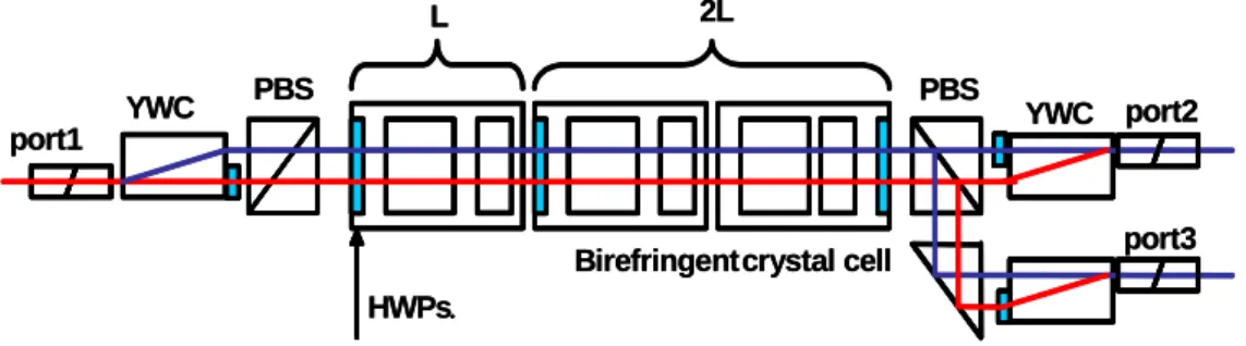
Birefringent crystal has long been used in designing optical filters; which includes birefringent crystal plates and polarizers. The two major types of birefringent filters are Lyot-Öhman filters and Šolc filters [36–38]. Both types are based on interference between polarized light, and require phase retardation among the components of light polarized parallel to the slow and the fast axes of the crystal, as light passes through it. Consequently, birefringent crystal is served as an optical delay line, and a half-wave plate is used to alter the polarization between the delay stages. The rotation of the half-wave plates can also be considered to be designed to generate various required Fourier frequency components. Figure 3.1 shows the configuration of the three-port interleaver employed by the birefringent crystal. At the input and outputs of the interleaver, an YVO4 walk-off crystal and a half-wave plate were used to ensure that the optical delay
cells contained only a single polarization. Each delay cell includes two birefringent crystals, namely YVO4 and Rutile (TiO2), to compensate for the temperature variation.
The lengths of YVO4 and Rutile can be determined using (1) and (2).
FSR c m L n L n −∆ = center = ∆ 1 1 2 2 λ (1)
(
∆n1L1−∆n2L2)
=0⇒∆n1L1β1−∆n2L2β2 =0 dT d (2) with i i i ; 1,2 i i i i d n dL d i n dT L dT dT λ β λ ∆ ≡ + = = ∆In (1) and (2), ∆n1 and ∆n2 indicate, respectively, the group index difference
between ordinary and extraordinary axes of YVO4 and Rutile. Moreover, c denotes the
speed of light, FSR represents the free spectral range, Li represents the length of the
19
represents the order of the birefringent wave plate and βιis the normalized variation in
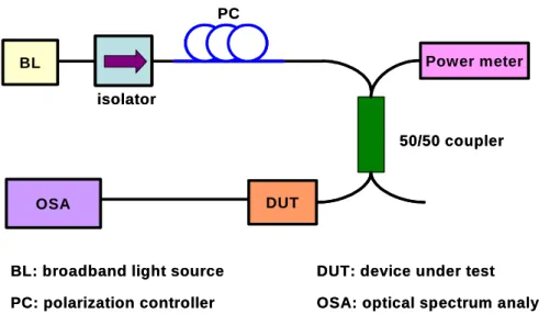
the wavelength with temperature. Figure 3.2 shows the measurement setup used to determine β. Since for normal incident light, each crystal forms a Fabry-Perot Etalon cavity from the facets reflection and the transmission spectra will have null points with FSR determined by the cavity length. When the temperature of the crystal is changed, the cavity length will change and the null points will start to drift accordingly.β can then be determined by measuring the drifting of the null point with temperature in the optical spectrum analyzer. For YVO4 and Rutile, the group index differences are 0.2139 and
0.2652, and the β are −26.54×10−61/°C and −99.06×10−61/°C, respectively. At the
central frequency of 193.5 THz, the values of β correspond to 5.13 and 19.17 GHz/°C, respectively. For a 100-GHz interleaver, FSR equals to 200 GHz, solving (1) and (2) yields the lengths of the YVO4 and Rutile crystals, which are 9.5697 and 2.0685 mm,
respectively [39]. After temperature compensation, the temperature drift is reduced to approximately 0.056 GHz/°C. This corresponds to about 3.7 GHz drift in temperature variation from 0 °C to 65 °C. One difficulty that could not be fully compensated during the design process was the wavelength dependence of refractive index, namely dispersion.
Figure 3.1: Possible configuration of a three-port L-2L interleaver.
L 2L PBS HWPs. Birefringentcrystal cell port1 port2 port3 (a) YWC PBS YWC . (a) .
PBS: Polarization beam splitter; YWC: YVO4walk off crystal; HWP: Half wave plate
L 2L PBS HWPs. Birefringentcrystal cell port1 port2 port3 (a) YWC PBS YWC . (a) .
However, as shown in Appendix I, with proper selection of crystal lengths, for typical C-band application (with center frequency 193.5 THz and total C-bandwidth 4 THz), the refractive index dispersion introduces center frequency offset of only 2 to 2.5 GHz.
The optimized wave plate angles were determined using the “minimize the integral square error” method, as shown in (3).
⎭ ⎬ ⎫ ⎩ ⎨ ⎧ −
∑
= N n n n x f f x 1 2 )] ( ) ( ˆ [ min (3) with 2 2 FSR f f FSR fc− ≤ n≤ c+ (4)In (3), xˆ(fn)is the desired target amplitude response and x(fn)is the real transmission
function. The transmission function is periodic, therefore, the errors can be summed over one FSR at the central frequency, fc. By changing the position of the half-wave plate at
the input walk-off crystal, the input polarization angle was shifted 90°and generates two delay responses. Minimizing (3) can yield the corresponding wave plate angles. Figure 3.3 presents the simulated amplitude and delay response of two types of
BL isolator PC Power meter 50/50 coupler DUT OSA
BL: broadband light source PC: polarization controller
DUT: device under test
OSA: optical spectrum analyzer BL isolator PC Power meter 50/50 coupler DUT OSA
BL: broadband light source PC: polarization controller
DUT: device under test
OSA: optical spectrum analyzer Figure 3.2: Measurement setup of birefringent crystal temperature sensitivity interleaver.
21
interleavers. This figure shows that changing the input polarization yields two interleavers with the same amplitude responses but opposite delay responses. Therefore, the cascaded interleaver pair will have constant delay and therefore the dispersion will approach zero. To design an interleaver with sharp edge response, higher Fourier frequency components must be included. Additional delay line stages are required to increase the highest Fourier frequency, and pass band, insertion loss, size, reliability and cost are all traded off against one another. For a 100 GHz interleaver,L-2L-2L can meet the pass band and delay requirements for 40 Gb/s transmission without difficulty. If only a 10 Gb/s signal is transmitted, an L-2L design will suffice.
3.2 Experimental Results of 100 GHz L-2L-2L Interleavers
After design analysis, an L-2L-2L interlever was fabricated to verify the design. Figure 3.4(a) and (b) show the measurement results of the re-centered transmission
responses in a frequency range from 191.8 THz to 195.5 THz at 0 Co, 23 Co and 65 Co, respectively. The figures clearly demonstrate successfully mitigation of the temperature variation. Figure 3.4(c) shows the 0.5 dB passband of different channels at 0 Co, 23 Co and 65 Co. The average 0.5 dB passband is about 73 GHz. Figure 3.4(d) shows the polarization dependent loss (PDL) of different channels at 0 Co, 23 Co and 65 Co. The average PDL is below 0.15 dB meaning that there is good control of on the alignment
-100 -50 0 50 100 -30 -25 -20 -15 -10 -5 0 Frequency (GHz) IL ( d B )
Transmission at Different Temperature
(a)
-40 -20 0 20 40 -3 -2.5 -2 -1.5 -1 -0.5 0 Frequency (GHz) IL ( d B )Transmission at Different Temperature
(b)
10 20 30 60 65 70 75 80 85 90 Channel # P a ssb a n d ( G H z ) 0.5 dB Bandwidth(c)
0 C 23 C 65 C 10 20 30 -0.4 -0.2 0 0.2 0.4 Channel # PD L ( d B)Polarization Dependent Loss
(d)
0 C23 C65 C
Figure 3.4: (a) Re-centered transmission at 0 °C, 23 °C and 65 °C. (b) Magnified Folded transmission at 0 °C, 23 °C and 65 °C. (c) 0.5 dB passband at 0 °C, 23 °C and 65 °C. (d) Polarization dependent loss 0 °C, 23 °C and 65 °C.
23
between the input fiber and the walk-off YVO4 crystal. The fiber alignment is similar to
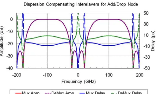
typical micro-optic fiber devices such as isolator, circulator and switch. The alignment need to be very careful and active alignment is needed. Figure 3.5 plots the measured amplitude and the delay responses of two types of 100-GHz interleavers. Figure 3.5(a)–(d) illustrate type A and B interleavers that have identical transmission spectra but reversed delay responses. Meanwhile, type A and B interleavers can be cascaded to generate a linear phase interleaver pair with a total dispersion near zero, a feature that is desirable, particularly in metro add/drop applications and/or high bit rate transmission systems.
Figure 3.5: (a), (b): Measured re-centered amplitude of Mux and Demux; (c), (d) measured re-centered delay of Mux and DeMux.
-100 -50 0 50 100 -25 -20 -15 -10 -5 0 Frequency (GHz) IL ( d B ) Type A Transmission (191.8-195.5THz) -100 -50 0 50 100 -25 -20 -15 -10 -5 0 Frequency (GHz) IL ( d B ) Type B Transmission (191.8-195.5THz) -100 -50 0 50 100 -6 -4 -2 0 2 4 6 Frequency (GHz) Grou p d e la y (ps )
Type A Delay (191.9, 193.9 and 195.3THz)
-100-6 -50 0 50 100 -4 -2 0 2 4 6 Frequency (GHz) Grou p d e la y (ps )
Type B Delay (191.9, 193.9 and 195.3THz)
(a) (b)
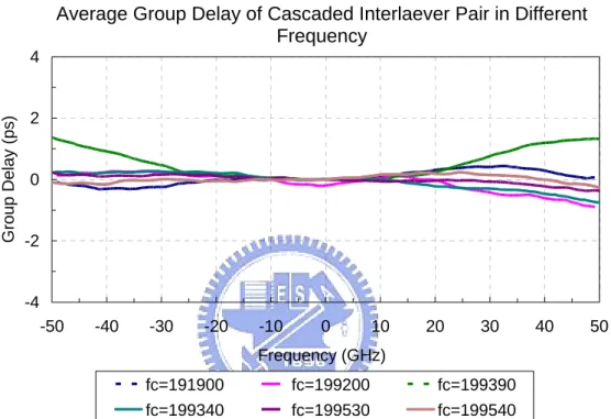
Figure 3.6 depicts the measured results that relate to seven cascaded interleaver pairs. The figure shows that the total delay is below 1ps within the pass band. These figures clearly show that interleavers with same amplitude response and opposite delay response were successfully designed.
Average Group Delay of Cascaded Interelaver Pair
-4 -2 0 2 4 -50 -40 -30 -20 -10 0 10 20 30 40 50 Frequency (GHz) G roup Delay (ps) fc=191900 fc=199200 fc=199390 fc=199340 fc=199530 fc=199540
Average Group Delay of Cascaded Interlaever Pair in Different Frequency
25
CHAPTER 4
LONG DISTANCE TRANSMISSION BY USING A
RECIRCULATING-LOOP
As the Internet traffic is increasing rapidly and DWDM technologies in current optical communication systems is getting matured, the functionalities and configurations of DWDM networks must be rapidly evolving accordingly [40]. The reconfigurability of WDM networks has the following features: The network’s configuration can be increased by bypassing, adding, or dropping the traffic and the capacity throughput enlarges when the traffic is multiplexed on the fiber by WDM. As a result, optical add-drop node will play an important role in high bite rate networks [41–43]. Two of experiments of optical add/drop technologies will be discussed and demonstrated in this chapter.
4.1 Recirculating Loop Test-bed
Modern optical fiber communication systems employ lots of components and hundreds or thousands of kilometers of optical fibers. In the lab environment, recirculationg optical loop tests-bed is a method for simulating long distance optical links to reduce the components, fiber span and the cost [6, 56]. Figure 4.1 illustrates the simple functions of the recirculating loop. Optical signals of limited duration are fed into an optical link as Figure 4.1(a). This optical link may consist of optical components, such as fiber coils, amplifiers, filters and so on. Then, in Figure 4.1(b), the source would be disconnected and allowed the signals to circulate within a closed optical loop. After a number of round-trips, loop would be opened by the loop switch and the circulating
signals are fed into the receiver, as displayed in Figure 4.1(c). Once the loop has been emptied, the signals are fed into the fiber loop by the switch again. Consequently, the optical loop switch is a core component that has to be precisely controlled. A simplified description of the operation of a recirculating loop by acousto-optic (AO) switches follows, as in Figure 4.2. The pulse duration defines the length of the fill cycle. The loop time is related to loop length by
fiber in light of Velocity length Loop Time Loop (τLoop)= .
Closing the transmit switch loads the data stream into the optical loop. After the loop fills with data (Loop Time), the transmit switch opens (turn off) and the loop switch closes (turn on). The loaded bit stream then recirculates around the loop. A delay circuit (Error Gate) sets the distance range monitored and detected by the receiver after many times of circulations in the loop. After that, the loop can be emptied, refilled, and a new measurement cycle can begin.
Receiver Fiber loop Receiver Fiber loop Receiver Fiber loop Loop SW Transmitter Transmitter Transmitter Receiver Fiber loop Receiver Fiber loop Receiver Fiber loop Loop SW Transmitter Transmitter Transmitter Receiver Fiber loop Receiver Fiber loop Receiver Fiber loop Loop SW Transmitter Transmitter Transmitter
Figure 4.1: Phase of a recirculating loop. (a) Filling the loop, (b) circulating, and (c) emptying the loop.
(a)
(b)
27
4.2 Add/Drop Applications in Fiber Ring Networks Based on A Reconfigurable Optical Add/Drop Multiplexer (ROADM)
The ultimate goal of high bit rate networks is to have a large traffic bandwidth capacity and a flexible and dynamic reconfigurability to provide diversified bandwidth management in the optical layers of future all optical networks. One of the key enabling elements is the reconfigurable optical add/drop multiplexer (ROADM) which can insert (add) and extract (drop) channels at specific wavelengths and provide various supervisions and reconfigurations that are required at the nodes of future DWDM networks [44]. Recently, different technologies have been utilized to ensure the functionality of ROADM, such as planar waveguide switches [45], MEMS switches [46], and liquid crystal switches [47]. It is highly desirable to have the flexibility of directing the dropped and added optical channel to any specific port in an ROADM to achieve a real dynamically reconfigurable network.Hence, a monolithic integrated silica-on-silicon
Figure 4.2: Timing diagram of the recirculating loop.
Time Time Time on off Loop switch Transmit switch
τ
Loop on off on off Error Gate Time Time Time on off Loop switch Transmit switchτ
Loopτ
Loop on off on off Error Gateplanar lightwave circuit (PLCs) with a cross-bar switch array is the most promising candidate as an ROADM [48]. Since the traffic pattern is highly diverse in metro optical networks, the wavelengths are frequently reconfigured. As a result, the cascadability and extinction ratios of add/drop functions of ROADMs are important limiting factors on the applications of ROADMs.
4.2.1 Characteristics of ROADM
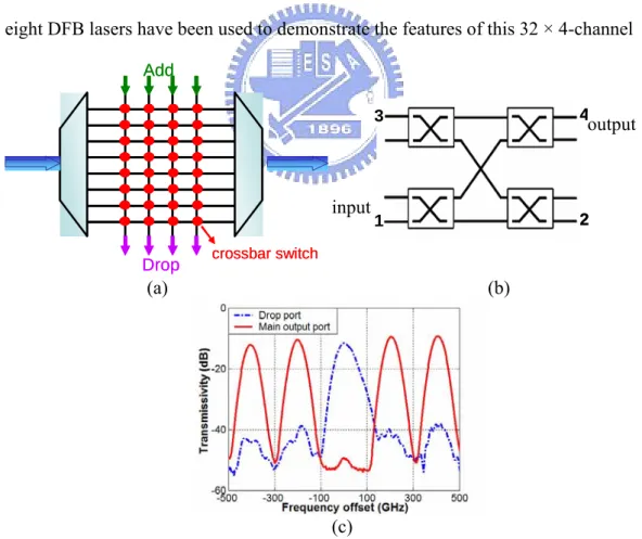
The system-on-a-chip ROADM used in this experiment is based on the cross-bar switch design to add/drop arbitrarily four out of 32 input wavelengths, its mask as shown in Figure 4.3. This ROADM is the first time to use a large-scale PLC device, 85.3 mm × 119 mm. Figure 4.4(a) schematically depicts the function of this ROADM. The 32 input WDM wavelengths, with a channel spacing of 200 GHz, are first demultiplexed by an array waveguide grating (AWG), and then sent to a 32 × 4 switching fabric for add/drop operations. Such a 32 × 4 switching fabric is scaled up by as many 2 × 2 cross-bar dilated thermo optic switches, as shown in Figure 4.4(b), and is built in the ROADM.
From: IEEE PTL, Vol. 15, No. 10, pp. 1413–1415, 2003.
mm 119mm 85. 3 m m 119 mm mm 119mm 85. 3 m m 119 mm
29
For example, signals launched to the thermo optics switch from port 1 would be routed to output port, port 4. At the same time, the signals can be dropped from port 2 and be added from port 3. All the reconfigured output channels are subsequently optically multiplexed using a second AWG. The detailed design rules, the operation principles, the architectures and the device characteristics of this ROADM can be found in [48]. Figure 4.4(c) displays the optical spectrum when one of the 32 input wavelengths is dropped. The extinction ratio of the dropped channel is more than 40 dB and the adjacent channel isolation exceeds 25 dB. It also can be seen clearly that the channel spacing of this ROADM is 200 GHz. Nevertheless, the high extinction ratio and isolation of the ROADM provide the feasibility for fiber network. Due to the limitation of laser sources, eight DFB lasers have been used to demonstrate the features of this 32 × 4-channel
Add
Drop crossbar switch
Add
Drop crossbar switch
(a) (b) Input Output 1 2 3 4 Input Output 1 2 3 4 input output (c)
Figure 4.4: (a) Schematic diagram of the ROADM, (b) crossbar switch of the ROADM, and (c) optical spectra obtained at drop port and main output port when one channel is dropped.