Wirel. Commun. Mob. Comput. 2002; 2:151– 167 (DOI: 10.1002/wcm.40)
A software architecture for GPRS session management
Yieh-Ran HaungŁ,†
Computer & Communications Research Laboratories
Industrial Technology Research Institute Hsinchu
Taiwan Yi-Bing Lin
Department of Computer Science and Information Engineering National Chiao Tung University Hsinchu
Taiwan
Summary
General packet radio service (GPRS) provides efficient access to the integrated services Internet from wireless networks. When the GPRS-attached mobile station attempts to send or receive data, a packet data protocol (PDP) context shall be established. The GPRS session management (SM) supports the PDP context handling, which consists of PDP context activation, deactivation, and modification procedures. In this paper, we propose an SM software architecture for the serving GPRS support node. Our design goals are to achieve compatibility, modularity, and flexibility. More importantly, our approach can accommodate the design of the SM software architecture for third-generation wireless networks. Copyright 2001 John Wiley & Sons, Ltd.
KEY WORDS GPRS PDP context session management SGSN 3G
Published online: 12 December 2001
1. Introduction
As Internet and wireless networks expand, the demand for wireless Internet access services will continue to increase. General packet radio service (GPRS) [1] provides efficient access to the integrated services Internet from wireless networks. With GPRS, the data services can be built using Internet protocol (IP) paradigm directly. GPRS has also evolved into
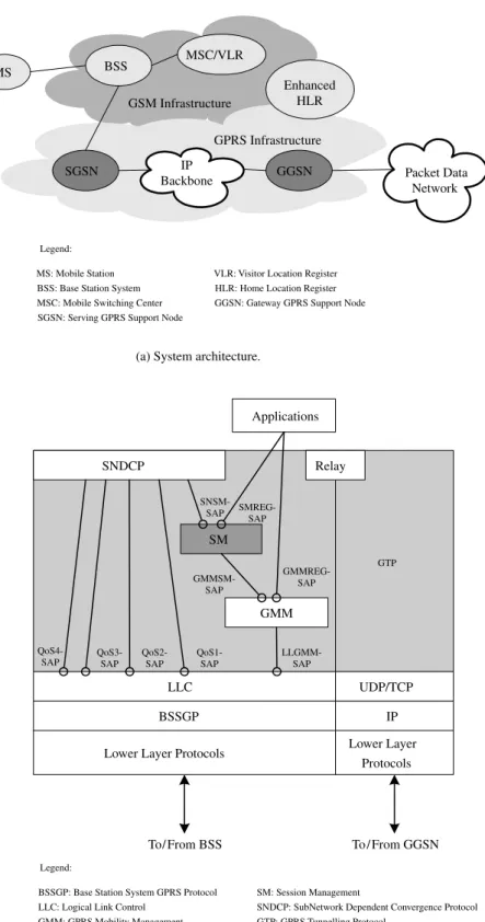
third-generation (3G) wireless networks [2] to sup-port IP multimedia applications. In order to provide an end-to-end packet transfer mode, GPRS adds two new network elements to the existing Global System for Mobile communications (GSM) infrastructure: the gateway GPRS support node (GGSN) and the serving GPRS support node (SGSN), as shown in Figure 1(a). We assume that the reader is familiar with the GSM terms such as BSS, MSC, VLR, and HLR. Details of these terms can be found in Reference [3]. The GGSN
ŁCorrespondence to: Yieh-Ran Haung, Computer & Communications Research Laboratories, Industrial Technology Research
Institute, Hsinchu, Taiwan.
†E-mail: [email protected]
provides connections and access to the integrated ser-vices Internet. It maintains routing information for the GPRS-attached mobile stations (MSs) to tunnel pro-tocol data units (PDUs) to the SGSN. The SGSN, in turn, is responsible for the delivery of packets to the MSs within its service area. In addition, the SGSN performs security, mobility management, and session management functions.
Figure 1(b) shows the protocol architecture of the SGSN, in which the service access points (SAPs)‡
are marked with circles. The GPRS tunnelling proto-col (GTP) [4] tunnels signalling messages and PDUs between the SGSN and the GGSN. UDP/IP is used as an unreliable path to transfer signalling messages and to tunnel connectionless PDUs. On the other hand, TCP/IP is used as a reliable path to tunnel connection-oriented PDUs. The relay transfers the signalling messages between the GTP and the GPRS mobil-ity management/session management (GMM/SM). In addition, it transfers the PDUs between the GTP and the subnetwork dependent convergence protocol (SNDCP) [5]. The GMM supports attach, detach, secu-rity, and location management functions. It provides the GMMREG-SAP for the applications to invoke the network-initiated detach procedure, and the GMMSM-SAP for the SM to send/receive SM signalling mes-sages to/from the logical link control (LLC) [6].
The SM supports packet data protocol (PDP) context§ handling of the GPRS-attached MSs. It pro-vides the SMREG-SAP for the applications to invoke the SM function. Moreover, through the SNSM-SAP, the SM informs the SNDCP about the PDP con-text information, i.e. negotiated QoS profile, activated SNDCP network SAP identifier (NSAPI) and the LLC SAPI assigned for this NSAPI, for transmit-ting PDUs. The SNDCP maps network-level char-acteristics onto the charchar-acteristics of the underlying network. It supports compression/decompression and segmentation/re-assembly of PDUs. The LLC sup-ports a highly reliable ciphered logical link between the MS and the SGSN. It provides four SAPs (i.e., QoS1–QoS4) for the SNDCP to carry PDUs with specific QoS requirement. It also provides the LLGMM-SAP for the GMM to transfer signalling messages between the MS and the SGSN. The base
‡At each SAP, services are provided or received by
exchanging corresponding sequences of primitives. § When the GPRS-attached MS attempts to send or receive data, a PDP context with a specific Quality-of-Service (QoS) profile between the MS and the GGSN shall be established.
station system GPRS protocol (BSSGP) [7] conveys QoS, radio, and routing-related information that is required to transmit PDUs between the BSS and the SGSN. For a complete description of the SGSN pro-tocol stacks and SAPs, the readers are referred to References [1, 8] and the references cited therein.
This paper focuses on the SM functions in the SGSN. The SM functions consist of PDP context acti-vation, deactiacti-vation, and modification procedures [9]. The PDP context activation procedure is used to establish a PDP context with a specific QoS pro-file. It may be initiated by the MS or be requested by the GGSN. The PDP context deactivation proce-dure is used to deactivate an existing PDP context. It may be initiated by the MS or by the network (i.e. SGSN or GGSN). The PDP context modification pro-cedure is invoked by the SGSN in order to modify PDP context parameters (e.g. QoS profile and radio priority) that were negotiated during the PDP context activation procedure or at previously performed PDP context modification procedures. In the following, we elaborate on these procedures.
1.1. PDP context activation
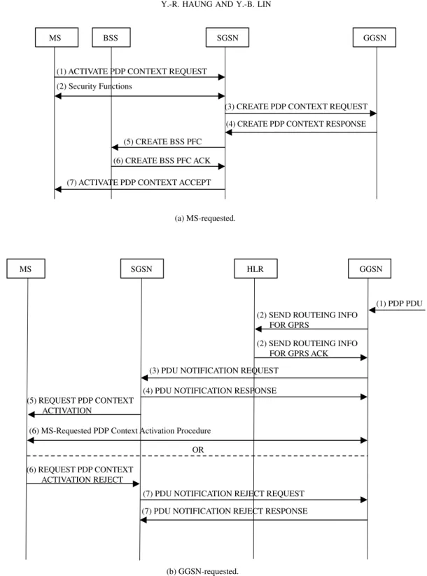
The message flow of the MS-requested PDP context activation procedure is shown in Figure 2(a), and is explained in the following steps.
(1) The MS sends an ACTIVATE PDP CONTEXT REQUEST message [9] with the requested PDP type, PDP address (optional)¶, access point name (APN)jj, and QoS profile to the SGSN.
(2) The GMM security functions may be executed for authentication and ciphering.
(3) The SGSN shall derive the GGSN address accord-ing to the APN selection rules [1]. If no GGSN address can be derived, then the SGSN rejects the activation request by sending an ACTIVATE PDP CONTEXT REJECT message [9] to the MS. If a GGSN address can be derived, the SGSN sends a CREATE PDP CONTEXT REQUEST message [4] with the requested PDP type, PDP address (optional)ŁŁ, APN, and QoS profile to the
GGSN.
(4) The GGSN may use APN to find an external network. In addition, the GGSN may restrict the ¶ The MS shall leave PDP address empty to request a dynamic PDP address.
jjThe APN may be used by the GGSN to differentiate
external networks.
ŁŁIf the MS requests a dynamic address, then the GGSN is
GTP Relay SNDCP SM GMM LLC BSSGP Lower Layer Protocols
To/ From BSS IP Lower Layer Protocols UDP/TCP To / From GGSN QoS1-SAP QoS2-SAP QoS3-SAP QoS4-SAP LLGMM-SAP GMMSM-SAP GMMREG-SAP SMREG-SAP SNSM-SAP Legend:
BSSGP: Base Station System GPRS Protocol SM: Session Management LLC: Logical Link Control
GMM: GPRS Mobility Management SAP: Service Access Point
SNDCP: SubNetwork Dependent Convergence Protocol GTP: GPRS Tunnelling Protocol Applications IP Backbone SGSN GGSN MS Packet Data Network Enhanced HLR GPRS Infrastructure BSS MSC/VLR GSM Infrastructure
(a) System architecture.
(b) SGSN protocol architecture.
Legend:
MS: Mobile Station VLR: Visitor Location Register
BSS: Base Station System MSC: Mobile Switching Center
HLR: Home Location Register GGSN: Gateway GPRS Support Node SGSN: Serving GPRS Support Node
MS SGSN GGSN
(3) CREATE PDP CONTEXT REQUEST (1) ACTIVATE PDP CONTEXT REQUEST
(2) Security Functions
(4) CREATE PDP CONTEXT RESPONSE
(7) ACTIVATE PDP CONTEXT ACCEPT
(a) MS-requested.
MS SGSN HLR GGSN
(b) GGSN-requested.
(1) PDP PDU (2) SEND ROUTEING INFO
FOR GPRS
(2) SEND ROUTEING INFO FOR GPRS ACK (3) PDU NOTIFICATION REQUEST
(4) PDU NOTIFICATION RESPONSE (5) REQUEST PDP CONTEXT
ACTIVATION
(6) MS-Requested PDP Context Activation Procedure OR
(7) PDU NOTIFICATION REJECT REQUEST (6) REQUEST PDP CONTEXT
ACTIVATION REJECT
(7) PDU NOTIFICATION REJECT RESPONSE BSS
(5) CREATE BSS PFC (6) CREATE BSS PFC ACK
Fig. 2. Message flow—PDP context activation procedure.
negotiated QoS profile given its capabilities and current load. The GGSN then returns a CREATE PDP CONTEX RESPONSE message [4] to the SGSN to indicate whether a PDP context has been created in the GGSN.
(5) The SGSN derives the aggregate BSS QoS profile (ABQP)CC from the negotiated QoS profile, and CCThe ABQP defines the QoS that must be provided by
the BSS for a given packet flow between the MS and the SGSN.
then sends a CREATE BSS packet flow context (PFC) message [7] with the requested ABQP to the BSS.
(6) The BSS may restrict the requested ABQP given its capabilities and the current load. If the PFC creation request was accepted, then the BSS returns a CREATE BSS PFC ACK message [7] to the SGSN.
(7) The SGSN selects radio priority based on the negotiated QoS profile, and returns an ACTI-VATE PDP CONTEXT ACCEPT message [9] to the MS. The SGSN is now able to route PDUs between the MS and the GGSN.
The message flow of the GGSN-requested PDP context activation procedure is shown in Figure 2(b), and is explained as follows.
(1) When receiving a PDP PDU the GGSN deter-mines if the activation procedure has to be initi-ated.
(2) The GGSN may send a SEND ROUTEING INFO FOR GPRS message [10] to the HLR to request the routing information. If the HLR determines that the request can be served, it returns a SEND ROUTEING INFO FOR GPRS ACK message [10] with the SGSN address to the GGSN.
(3) The GGSN shall send a PDU NOTIFICATION REQUEST message [4] with the requested PDP type and PDP address to the SGSN.
(4) The SGSN returns a PDU NOTIFICATION RESPONSE message [4] to inform the GGSN whether the activation will proceed or not. (5) If the activation will proceed, the SGSN sends a
REQUEST PDP CONTEXT ACTIVATION mes-sage [9] to request the MS to activate the PDP context indicated with PDP address.
(6) Upon receipt of a REQUEST PDP CONTEXT ACTIVATION message, the MS shall either acti-vate the PDP context with the MS-requested PDP context activation procedure or shall reject the activation request by sending a REQUEST PDP CONTEXT ACTIVATION REJECT message [9] to the SGSN.
(7) If the MS does not respond or refuses the acti-vation request, the SGSN sends a PDU NOTIFI-CATION REJECT REQUEST message [4] with cause ‘MS not responding’ or ‘MS refusing’ to the GGSN. The GGSN returns a PDU NOTI-FICATION REJECT RESPONSE message [4] to the SGSN.
1.2. PDP context deactivation
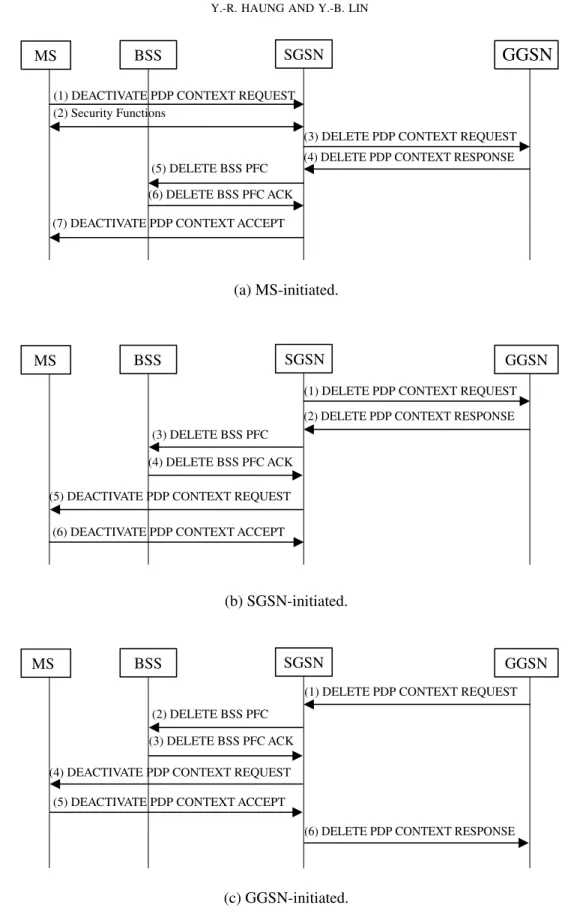
The message flow of the MS-initiated PDP context deactivation procedure is shown in Figure 3(a), and is explained in the following steps.
(1) The MS sends a DEACTIVATE PDP CONTEXT REQUEST message [9] to the SGSN.
(2) The GMM security functions may be executed for authentication and ciphering.
(3) The SGSN sends a DELETE PDP CONTEXT REQUEST message [4] to the GGSN.
(4) The GGSN removes the PDP context and returns a DELETE PDP CONTEXT RESPONSE mes-sage [4] to the SGSN.
(5) The SGSN sends a DELETE BSS PFC mes-sage [7] to the BSS.
(6) The BSS deletes the corresponding PFC and returns a DELETE BSS PFC ACK message [7] to the SGSN.
(7) The SGSN returns a DEACTIVATE PDP CON-TEXT ACCEPT message [9] to the MS. The message flow of the SGSN-requested PDP con-text deactivation procedure is shown in Figure 3(b). Steps (1)– (4) are the same as Steps (3)– (6) described in Figure 3(a). In Step (5), the SGSN sends a DEAC-TIVATE PDP CONTEXT REQUEST message to the MS. The MS then returns a DEACTIVATE PDP CONTEXT ACCEPT message to the SGSN in Step (6). The message flow of the GGSN-requested PDP context deactivation procedure is shown in Figure 3(c). In Step (1), the GGSN sends a DELETE PDP CONTEXT REQUEST message to the SGSN. Steps (2)– (5) are the same as Steps (3)– (6) described in Figure 3(b). In Step (6), the SGSN returns a DELETE PDP CONTEXT RESPONSE message to the GGSN. The GGSN then releases the network resources (e.g. IP address and bandwidth) and makes them available for subsequent activation by other MSs.
1.3. PDP context modification
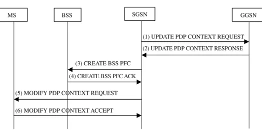
The message flow of the PDP context modification procedure is shown in Figure 4, and is explained as follows.
(1) The SGSN may send an UPDATE PDP CON-TEXT REQUEST message [4] with the negoti-ated QoS profile to the GGSN.
(2) The GGSN may restrict the negotiated QoS profile given its capabilities and the current
MS SGSN
GGSN
(3) DELETE PDP CONTEXT REQUEST (1) DEACTIVATE PDP CONTEXT REQUEST
(2) Security Functions
(4) DELETE PDP CONTEXT RESPONSE
(7) DEACTIVATE PDP CONTEXT ACCEPT
(a) MS-initiated. (b) SGSN-initiated. (c) GGSN-initiated. BSS (5) DELETE BSS PFC (6) DELETE BSS PFC ACK MS SGSN GGSN
(1) DELETE PDP CONTEXT REQUEST
(5) DEACTIVATE PDP CONTEXT REQUEST
(2) DELETE PDP CONTEXT RESPONSE
(6) DEACTIVATE PDP CONTEXT ACCEPT
BSS
(3) DELETE BSS PFC (4) DELETE BSS PFC ACK
MS SGSN GGSN
(1) DELETE PDP CONTEXT REQUEST
(4) DEACTIVATE PDP CONTEXT REQUEST
(6) DELETE PDP CONTEXT RESPONSE (5) DEACTIVATE PDP CONTEXT ACCEPT
BSS
(2) DELETE BSS PFC (3) DELETE BSS PFC ACK
MS SGSN GGSN
(1) UPDATE PDP CONTEXT REQUEST
(5) MODIFY PDP CONTEXT REQUEST
(2) UPDATE PDP CONTEXT RESPONSE
(6) MODIFY PDP CONTEXT ACCEPT BSS
(3) CREATE BSS PFC (4) CREATE BSS PFC ACK
Fig. 4. Message flow—PDP context modification procedure. load, and returns an UPDATE PDP CONTEXT
RESPONSE message [4] to the SGSN.
(3) The SGSN sends a CREATE BSS PFC message‡‡
[7] with the requested ABQP to the BSS. (4) If the PFC modification request was accepted,
then the BSS returns a CREATE BSS PFC ACK message [7] to the SGSN.
(5) The SGSN sends a MODIFY PDP CONTEXT REQUEST message [9] with the negotiated QoS profile, radio priority, and LLC SAPI to the MS. (6) The MS acknowledges by returning a MODIFY PDP CONTEXT ACCEPT message [9] to the SGSN. If the MS does not accept the negotiated QoS profile, it shall deactivate the PDP context with the MS-initiated PDP context deactivation procedure.
In this paper, we propose an SM software archi-tecture to support the above PDP context procedures in the SGSN. The goals of our design are as follows. ž Modularity: The SM components are implemented
as modules.
ž Compatibility: Our design strives to maintain com-patibility with the current and upcoming standards for GPRS.
ž Flexibility: The configuration parameters of the SM components can be dynamically changed at run time.
The paper is organized as follows. Section 2 pre-sents the SM software architecture and explains how
‡‡If the PFC already exists, the BSS shall interpret the
message as a modification request.
it achieves modularity and compatibility. In addition, based on our proposed architecture, we demonstrate the design of the SM software architecture for 3G wireless networks. Section 3 describes the initiation and configuration procedures for the SM software and shows how the flexibility goal is achieved. In Section 4, we elaborate on the SM procedures in the SGSN. Finally, Section 5 concludes our work.
2. The SM Software Architecture
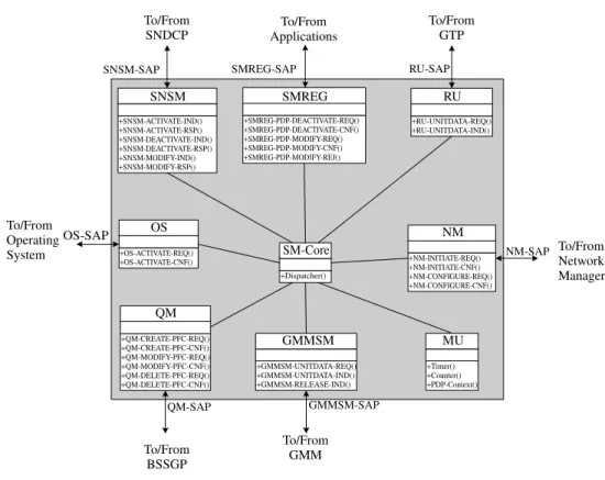
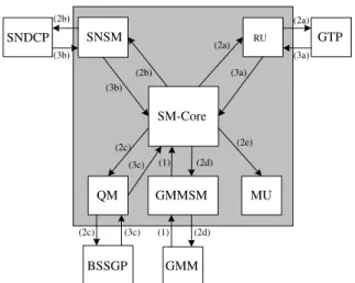
The primary goal of our proposed architecture is to build a modular, compatible, and flexible software that supports SM functions. Figure 5 shows the SM software architecture for the SGSN. The SM-Core is the kernel of the SM software, which consists of functions that interact with SM components. When an invocation is received from an SM component, the SM-Core dispatches the corresponding compo-nents to complete the tasks triggered by that invoca-tion. The interaction between an SM component (e.g. SNSM) and a protocol entity (e.g. SNDCP) takes place using primitives across a SAP (e.g. SNSM-SAP). The standardized primitives of a SAP allow the SM components to be defined and implemented independently of each other, thereby achieving the modularity goal. In addition, by implementing the standardized GPRS primitives in the SM components, we guarantee compatibility with various versions of the GPRS standards.
2.1. SM components
The design of the primitives for the SM components follows the primitive flow model shown in Figure 6.
+SNSM-ACTIVATE-IND() +SNSM-ACTIVATE-RSP() +SNSM-DEACTIVATE-IND() +SNSM-DEACTIVATE-RSP() +SNSM-MODIFY-IND() +SNSM-MODIFY-RSP() SNSM +SMREG-PDP-DEACTIVATE-REQ() +SMREG-PDP-DEACTIVATE-CNF() +SMREG-PDP-MODIFY-REQ() +SMREG-PDP-MODIFY-CNF() +SMREG-PDP-MODIFY-REJ() SMREG +Dispatcher() SM-Core +RU-UNITDATA-REQ() +RU-UNITDATA-IND() RU +NM-INITIATE-REQ() +NM-INITIATE-CNF() +NM-CONFIGURE-REQ() +NM-CONFIGURE-CNF() NM +OS-ACTIVATE-REQ() +OS-ACTIVATE-CNF() OS +GMMSM-UNITDATA-REQ() +GMMSM-UNITDATA-IND() +GMMSM-RELEASE-IND() GMMSM +Timer() +Counter() +PDP-Context() MU +QM-CREATE-PFC-REQ() +QM-CREATE-PFC-CNF() +QM-MODIFY-PFC-REQ() +QM-MODIFY-PFC-CNF() +QM-DELETE-PFC-REQ() +QM-DELETE-PFC-CNF() QM GMMSM-SAP To/From GMM To/From BSSGP SMREG-SAP To/From Applications RU-SAP To/From GTP SNSM-SAP To/From SNDCP NM-SAP To/From Network Manager OS-SAP To/From Operating System QM-SAP
Fig. 5. SM software architecture.
Service User Service Provider REQ CNF/REJ IND RSP Initiator Responder
Fig. 6. Primitive flow model.
A primitive can be one of four types: request (REQ), indication (IND), response (RSP), and confirm/reject (CNF/REJ). The REQ primitive is initiated by the vice user of a protocol entity called initiator. The ser-vice provider of the initiator then delivers the request to the corresponding protocol entity called responder. When the service provider of the responder receives the request, it informs the service user by issuing the IND primitive. The service user of the respon-der then may send the RSP primitive to the service
provider. After the service provider of the initiator receives this response, it issues the CNF/REJ primi-tive to confirm/reject the request. Descriptions of SM components are given below.
2.1.1. SM Registration
The SM Registration (SMREG) provides the prim-itives at the SMREG-SAP that interfaces the SM software (i.e. service provider) with the application (i.e. service user). The SMREG primitives take the form of REQ or CNF/REJ, and are explained as fol-lows.
ž SMREG-PDP-DEACTIVATE: The REQ primitive initiates a PDP context deactivation procedure. The CNF primitive confirms that the PDP context deactivation procedure has been concluded. ž SMREG-PDP-MODIFY: The REQ primitive
initi-ates a PDP context modification procedure. The CNF/REJ primitive confirms that the PDP context modification procedure has been concluded. 2.1.2. SNDCP SM
The SNDCP SM (SNSM) provides the primitives at the SNSM-SAP that interfaces SM software (i.e.
service provider) with the SNDCP entity (i.e. service user). The SNSM primitives take the form of IND or RSP, and are explained as follows.
ž SNSM-ACTIVATE: The IND primitive informs the SNDCP entity that an SNDCP NSAPI has been activated for data transfer. It also informs the SNDCP entity about the negotiated QoS profile and the LLC SAPI assigned for this NSAPI. The RSP primitive informs the SM software that the indicated SNDCP NSAPI is now in use.
ž SNSM-DEACTIVATE: The IND primitive informs the SNDCP entity that an SNDCP NSAPI has been de-allocated and cannot be used anymore. The RSP primitive informs the SM software that the indicated SNDCP NSAPI is no longer in use. ž SNSM-MODIFY: The IND primitive informs the
SNDCP entity about the change of the QoS profile for an SNDCP NSAPI and the LLC SAPI assigned for this NSAPI. It also indicates that an NSAPI shall be created, together with the re-negotiated QoS profile and the assigned SAPI. The RSP prim-itive informs the SM software that the indicated SNDCP NSAPI and the negotiated QoS profile are now in use.
2.1.3. Relay unit
The relay unit (RU) transfers the signalling messages between the SM software (i.e. service user) and the GTP entity (i.e. service provider). The RU primitives take the form of REQ or IND, and are explained as follows.
ž RU-UNITDATA: The REQ primitive requests the GTP entity to forward a GTP message to the GGSN. With the IND primitive, the GTP entity forwards a GTP message received from the GGSN to the SM software.
2.1.4. QoS manager
The QoS manager (QM) acts as the admission con-troller and the resource manager. The QM-SAP pro-vides an interface for the SM software (i.e. service user) to invoke the BSSGP entity (i.e. service pro-vider) to create, modify, or delete the BSS PFC. The QM primitives take the form of REQ or CNF, and are explained as follows.
ž QM-CREATE-PFC: The REQ primitive initiates the BSS PFC creation. The CNF primitive indicates
whether the requested PFC has been created in the BSS or not.
ž QM-DELETE-PFC: The REQ primitive initiates the BSS PFC deletion. The CNF primitive informs the SM software whether the indicated PFC has been deleted in the BSS.
ž QM-MODIFY-PFC: The REQ primitive initiates the BSS PFC modification. The CNF primitive indicates whether the PFC modification request was accepted by the BSS or not.
2.1.5. GMM SM
The GMM SM (GMMSM) provides the primitives at the GMMSM-SAP that interfaces the SM software (i.e. service user) with the GMM entity (i.e. service provider). The GMMSM primitives take the form of REQ or IND, and are explained as follows.
ž GMMSM-UNITDATA: The REQ primitive requests the GMM entity to forward an SM message to the MS. Upon receipt of an SM message from the MS, the GMM entity forwards it to the SM software by using the IND primitive.
ž GMMSM-RELEASE: The IND primitive informs the SM software that the MS has been detached, and therefore the PDP contexts are not valid any-more.
2.1.6. Maintenance unit and operating service The Maintenance unit (MU) is responsible for main-taining SM parameters (i.e. timers§§ and retransmis-sion counters¶¶). It is also responsible for creating and maintaining the PDP contexts. The operating ser-vice (OS) encapsulates all operating system depen-dencies of the SM software. The operating system functions (e.g. memory and queue management) re-quired by the SM software is provided by the OS-SAP. The OS primitives take the form of REQ or CNF, and are explained as follows.
ž OS-ACTIVATE: The REQ primitive activates the operating system functions. The CNF primitive is used by the operating system to confirm the activation procedure.
§§ The timer holds the maximum waiting time for a response of a request message.
¶¶ The retransmission counter holds the maximum number of attempts made by GMM to send a request message.
2.1.7. Network manager
The Network manager (NM) manages the SM soft-ware configuration parameters. The NM primitives take the form of REQ or CNF, and are explained as follows.
ž NM-INITIATE: The REQ primitive initiates the SM software. With the CNF primitive, the SM software confirms the initiation procedure.
ž NM-CONFIGURE: The REQ primitive configures specific components of the SM software. With the CNF primitive, the SM software confirms the configuration procedure.
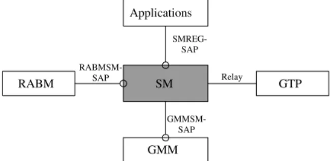
2.2. Remarks for the SM software architecture Our design methodology can be used to develop the SM software architecture for 3G wireless networks. Figure 7 shows the SM protocol architecture of 3G wireless networks [11]. The SM entity interacts with the GTP entity through the relay, uses services pro-vided by the GMM entity through the GMMSM-SAP, and provides services to the applications and the radio access bearer manager (RABM) entity through the SMREG-SAP and the RABMSM-SAP, respectively. The relay, GMMSM-SAP, and SMREG-SAP are identical to that for GPRS SM. Only the RABMSM-SAP is different. Thus, to extend our SM software architecture for 3G SM, we need to develop a new RABMSM component to replace the SNSM compo-nent. The SM-Core and the NM component need to be modified slightly to accommodate the RABMSM component. In addition, the QM component needs to be modified to accommodate the radio access net-work application Part (RANAP)jjjj entity. The other
RABM SM GMM RABMSM-SAP GMMSM-SAP SMREG-SAP Applications GTP Relay
Fig. 7. Protocol architecture of 3G SM.
jjjjIn 3G wireless networks, the RANAP [12], instead of
BSSGP, is used to convey QoS-related information between the radio network subsystem (RNS) and the SGSN.
SM components are not affected by the introduction of the RABMSM component and the RANAP entity.
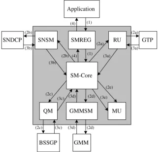
3. The Software Initiation and Configuration
By using the initiation procedure, the network man-ager initiates the global data structures of the SM software and activates operating system functions. In addition, using the configuration procedure, the specific components of the SM software can be con-figured at run time via the network manager interface (i.e. NM-SAP). The details are elaborated as follows. 3.1. Initiation
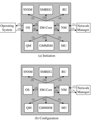
The initiation procedure is illustrated in Figure 8(a), and is explained in the following steps.
(1) The network manager sends an NM-INITIATE-REQ primitive to the NM to invoke the initiation procedure. The NM then invokes the SM-Core. (2) The SM-Core dispatches all SM components to
initiate the global data structures.
(3) The OS sends an OS-ACTIVATE-REQ primitive to the operating system to activate operating sys-tem functions.
(4) After completing the activation procedure, the operating system acknowledges it by sending an OS-ACTIVATE-CNF primitive to the OS. The OS then informs the SM-Core of the completion of activation procedure.
(5) The SM-Core dispatches the NM to send an NM-INITIATE-CNF primitive to the network manager, which indicates the completion of the initiation procedure.
3.2. Configuration
The configuration procedure is illustrated in Figure 8(b), and is explained as follows.
(1) To initiate the configuration procedure, the net-work manager sends an NM-CONFIGURE-REQ primitive to the NM. The NM then invokes the SM-Core.
(2) The SM-Core dispatches the affected compo-nents to perform the configuration procedure. For example, when the network congestion situation occurs, the QM shall be invoked to reduce the maximum number of PDP contexts used in per-forming admission control.
SM-Core SNSM NM OS GMMSM RU SMREG QM MU Network Manager Operating System (1) (1) (2) (2) (2) (2) (2) (2) (2) (3) (4) (4) (5) (5) (a) Initiation SM-Core SNSM NM OS GMMSM RU SMREG QM MU Network Manager (1) (1) (2) (2) (2) (2) (2) (2) (2) (3) (3) (b) Configuration
Fig. 8. Software initiation and configuration procedures. (3) After completing the configuration procedure,
the SM-Core dispatches the NM to acknowl-edge the configuration procedure by sending an NM-CONFIGURE-CNF primitive to the network manager.
4. The SM Procedures in the SGSN
Based on our proposed SM software architecture, we show how the SGSN behaves in the PDP context activation, deactivation, and modification procedures. 4.1. PDP context activation
As shown in Figure 2, this procedure establishes a PDP context with a specific QoS profile between the MS and the GGSN. The procedure may be requested by the MS or by the GGSN.
4.1.1. MS-requested
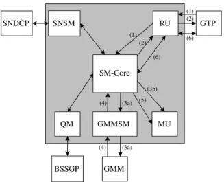
Figure 9 illustrates the behaviour of the SGSN in the MS-requested PDP context activation procedure. Each step is explained as follows.
(1) The GMM entity sends a GMMSM-UNIT-DATA-IND primitive with an ACTIVATE PDP
SM-Core SNSM BSSGP GMMSM RU QM MU (4a) (3a) (4b) GTP GMM SNDCP (2a) (2a) (3a) (6) (6) (1) (1) (2b) (2b) (3b) (3b) (5) (5) (4a)
Fig. 9. MS-requested PDP context activation procedure.
CONTEXT REQUEST message received from the MS (see Step (1) in Figure 2(a)) to the GMMSM. The GMMSM then informs the SM-Core that the MS requests the establishment of a PDP context.
(2a) The SM-Core shall derive the GGSN address according to the APN selection rules. If no GGSN address can be derived, then the SM-Core rejects the PDP context activation by dispatching the GMMSM to send a GMMSM-UNITDATA-REQ primitive with an ACTIVATE PDP CONTEXT REJECT message to the GMM entity. In this case, Steps (2b)– (6) are skipped. If a GGSN address can be derived, then the SM-Core dispatches the RU to send an RU-UNITDATA-REQ primitive to the GTP entity for forwarding a CREATE PDP CONTEXT REQUEST message to the GGSN (see Step (3) in Figure 2(a)).
(2b) The SM-Core dispatches the QM to perform admission control and resource allocation, to derive the ABQP, and then to send a QM-CREATE-PFC-REQ primitive to the BSSGP entity for forwarding a CREATE BSS PFC mes-sage with the ABQP to the BSS (see Step (5) in Figure 2(a)).
(3a) The GTP entity sends an RU-UNITDATA-IND primitive with a CREATE PDP CONTEXT RESPONSE message received from the GGSN (see Step (4) in Figure 2(a)) to the RU. The RU then informs the SM-Core whether the PDP context activation request was accepted or not. If the PDP context activation request was not accepted, then the SM-Core dispatches the GMMSM to send a GMMSM-UNITDATA-REQ
primitive with an ACTIVATE PDP CONTEXT REJECT message to the GMM entity, and Steps (4b)–(6) are skipped.
(3b) The BSSGP entity sends a QM-CREATE-PFC-CNF primitive with a CREATE BSS PFC ACK message received from the BSS (see Step (6) in Figure 2(a)) to the QM. The QM then informs the SM-Core that the PFC creation request was accepted. If the PFC creation request was not accepted (i.e. a CREATE BSS PFC NACK message was received), then the SM-Core dis-patches the GMMSM to send a GMMSM-UNITDATA-REQ primitive with an ACTIVATE PDP CONTEXT REJECT message to the GMM entity, and Steps (4b)– (6) are skipped.
(4a) If the creation of the GGSN PDP context and the BSS PFC was accepted, then the SM-Core dispatches the SNSM to send an SNSM-ACTIVATE-IND primitive to inform the SNDCP entity that an SNDCP NSAPI has been activated for data transfer. If only the cre-ation of the GGSN PDP context was successful, then the SM-Core dispatches the RU to send a RU-UNITDATA-REQ primitive to the GTP entity for forwarding a DELETE PDP CON-TEXT REQUEST message to the GGSN, which instructs the GGSN to release the resource reser-vations. If only the creation of the BSS PFC was successful, then the SM-Core dispatches the QM to send a QM-DELETE-PFC-REQ primitive to the BSSGP entity for forwarding a DELETE BSS PFC message to the BSS, which requests the BSS to perform resource de-allocation. (4b) The SM-Core dispatches the MU to create the
PDP context.
(5) Upon receipt of an SNSM-ACTIVATE-IND primitive from the SNSM, the SNDCP entity sends an SNSM-ACTIVATE-RSP to the SNSM to inform the SM-Core that the indicated SNDCP NSAPI is now in use.
(6) The SM-Core dispatches the GMMSM to send a GMMSM-UNITDATA-REQ primitive to the GMM entity for forwarding an ACTIVATE PDP CONTEXT ACCEPT message to the MS (see Step (7) in Figure 2(a)).
4.1.2. GGSN-requested
Figure 10 illustrates the action of the SGSN in the GGSN-requested PDP context activation procedure. Each step is explained as follows.
SM-Core SNSM BSSGP GMMSM RU QM MU (2) (3b) GTP GMM SNDCP (1) (1) (6) (3a) (3a) (4) (4) (5) (2) (6)
Fig. 10. GGSN-requested PDP context activation procedure.
(1) The GTP entity sends an RU-UNITDATA-IND primitive with a PDU NOTIFICATION REQUEST message received from the GGSN (see Step (3) in Figure 2(b)) to the RU. The RU then informs the SM-Core that the PDP context activation was requested by the GGSN. (2) If the SGSN has no information about that
MS, the SM-Core dispatches the RU to send an RU-UNITDATA-REQ primitive to the GTP entity for forwarding a PDU NOTICATION RESPONSE message to the GGSN with cause ‘IMSI not known’ or ‘MS detached’. If the SGSN has information about that MS, the cause shall be ‘Activation proceeds’ (see Step (4) in Figure 2(b)). If the cause is ‘Activation pro-ceeds’, Steps (3a)– (6) are executed. Otherwise, these steps are skipped.
(3a) The SM-Core dispatches the GMMSM to send a GMMSM-UNITDATA-REQ primitive to the GMM entity for forwarding a REQUEST PDP CONTEXT ACTIVATION message to request the MS to activate the indicated PDP context (see Step (5) in Figure 2(b)).
(3b) The SM-Core dispatches the MU to start the timer T3385 [9] and retransmission counters. (4) The GMM entity sends a
GMMSM-UNIT-DATA-IND primitive with an ACTIVATE PDP CONTEXT REQUEST message or a REQUEST PDP CONTEXT ACTIVATION REJECT mes-sage received from the MS (see Step (6) in Figure 2(b)) to the GMMSM. The GMMSM then informs the SM-Core whether the PDP con-text activation request was accepted or not.
(5) The SM-Core dispatches the MU to stop the timer T3385 and retransmission counter. If the message at Step (4) is ‘ACTIVATE PDP CON-TEXT REQUEST’, then Steps (2a)–(6) des-cribed in Figure 9 are executed. Otherwise, Step (6) is executed. Notice that, if the message indi-cated at Step (4) is not received within T3385, then Step (3a) shall be repeated a maximum of four times. On the fifth expiry of T3385, the SM-Core shall abort the activation procedure. (6) The SM-Core dispatches the RU to send an
RU-UNITDATA-REQ primitive to the GTP entity for forwarding a PDU NOTIFICATION REJECT REQUEST message to the GGSN. The GTP entity sends an RU-UNITDATA-IND primitive with a PDU NOTIFICATION REJECT RESPONSE message received from the GGSN to the RU (see Step (7) in Figure 2(b)). The RU then informs the SM-Core.
4.2. PDP context deactivation
As shown in Figure 3, this procedure deactivates an existing PDP context between the MS and the GGSN. The procedure may be initiated by the MS or the network (i.e. SGSN or GGSN).
4.2.1. MS-initiated
The action of the SGSN in the MS-initiated PDP con-text deactivation procedure is illustrated in Figure 11, and is explained as follows.
(1) The GMM entity sends a GMMSM-UNIT-DATA-IND primitive with a DEACTIVATE
SM-Core SNSM BSSGP GMMSM RU QM MU (2b) (3a) (2e) GTP GMM SNDCP (2a) (2a) (3a) (2d) (2d) (1) (1) (2c) (2c) (3b) (3b) (2b) (3c) (3c)
Fig. 11. MS-initiated PDP context deactivation procedure.
PDP CONTEXT REQUEST message received from the MS (see Step (1) in Figure 3(a)) to the GMMSM. The GMMSM then informs the SM-Core that the MS requests the deactivation of a PDP context. Notice that, if the GMM entity sends a GMMSM-RELEASE-IND prim-itive to the GMMSM to inform the SM-Core that the MS has been detached, then Step (2d) is skipped.
(2) The SM-Core dispatches the affected compo-nents to perform the deactivation procedure. (a) The RU sends an RU-UNITDATA-REQ
primitive to the GTP entity for forward-ing a DELETE PDP CONTEXT REQUEST message to the GGSN (see Step (3) in Figure 3(a)).
(b) The SNSM sends an SNSM-DEACTIVATE-IND primitive to inform the SNDCP entity that an SNDCP NSAPI has been de-allocated and cannot be used anymore. (c) The QM performs resource de-allocation
and sends a QM-DELETE-PFC-REQ prim-itive to the BSSGP entity for forwarding a DELETE BSS PFC message to the BSS (see Step (5) in Figure 3(a)).
(d) The GMMSM sends a GMMSM-UNIT-DATA-REQ primitive to the GMM entity for forwarding a DEACTIVATE PDP CON-TEXT ACCEPT message to the MS (see Step (7) in Figure 3(a)).
(e) The MU changes the PDP context state into INACTIVEŁŁŁ. The PDP context is deleted
after an implementation-dependent timeout period.
(3a) The GTP entity sends an RU-UNITDATA-IND primitive with a DELETE PDP CONTEXT RESPONSE message received from the GGSN (see Step (4) in Figure 3(a)) to the RU. The RU then informs the SM-Core that the PDP context was deleted.
(3b) Upon receipt of an SNSM-DEACTIVATE-IND primitive from the SNSM, the SNDCP entity sends an SNSM-DEACTIVATE-RSP to the
ŁŁŁThe PDP context exists in one of two states, i.e.
INAC-TIVE and ACINAC-TIVE. The INACINAC-TIVE state characterizes the data service for a certain PDP address of the MS as not activated. In ACTIVE state, the PDP context for the PDP address in use is activated in the MS, the SGSN, and the GGSN.
SNSM to inform the SM-Core that the indicated SNDCP NSAPI is no longer in use.
(3c) The BSSGP entity sends a QM-DELETE-PFC-CNF primitive with a DELETE BSS PFC ACK message received from the BSS (see Step (6) in Figure 3(a)) to the QM. The QM then informs the SM-Core that the PFC was deleted.
4.2.2. SGSN-initiated
The behaviour of the SGSN in the SGSN-initiated PDP context deactivation procedure is shown in Figure 12, and is explained in the following steps.
(1) The application sends an SMREG-PDP-DE-ACTIVATE-REQ primitive to the SMREG to initiate the PDP context deactivation procedure. The SMREG then invokes the SM-Core. (2) The SM-Core dispatches the affected
compo-nents to perform the deactivation procedure. Steps (2a)–(2c) are exactly the same as Steps (2a)– (2c) described in Figure 11.
(d) The GMMSM sends a GMMSM-UNIT-DATA-REQ primitive to the GMM entity for forwarding a DEACTIVATE PDP CON-TEXT REQUEST message to the MS to deactivate the indicated PDP context (see Step (5) in Figure 3(b)).
(e) The MU starts the timer T3395 [9] and retransmission counter. In addition, the
SM-Core SNSM BSSGP GMMSM RU SMREG QM MU (2b) (1) (3a) (2e) GTP GMM SNDCP Application (1) (2a) (2a) (3a) (3e) (2d) (2d) (3d) (3d) (3c) (2c) (3b) (3b) (2b) (4) (4) (3c) (2c)
Fig. 12. SGSN-initiated PDP context deactivation procedure.
MU changes the PDP context state into INACTIVE. The PDP context is deleted after an implementation-dependent timeout period.
(3) Steps (3a)– (3c) are the same as Steps (3a)–(3c) described in Figure 11.
(3d) The GMM entity sends a GMMSM-UNIT-DATA-IND primitive with a DEACTIVATE PDP CONTEXT ACCEPT message received from the MS (see Step (6) in Figure 3(b)) to the GMMSM. The GMMSM then informs the SM-Core that the PDP context deactivation request was accepted.
(3e) The SM-Core dispatches the MU to stop the timer T3395 and retransmission counter. Notice that, if the message indicated at Step (3d) is not received within T3395, then Step (2d) shall be repeated a maximum of four times. On the fifth expiry of T3395, the SM-Core shall dispatch the MU to erase the PDP context-related data for that MS.
(4) The SM-Core dispatches the SMREG to send an SMREG-PDP-DEACTIVATE-CNF primitive to inform the application that the PDP context deactivation procedure has been concluded.
4.2.3. GGSN-initiated
Figure 13 shows the action of the SGSN in the GGSN-initiated PDP context deactivation procedure. Each step is explained as follows.
SM-Core SNSM BSSGP GMMSM RU QM MU (2b) (4) (2e) GTP GMM SNDCP (1) (1) (4) (3e) (2d) (2d) (3d) (3d) (2c) (3c) (3b) (3b) (2b) (2c) (3c)
Fig. 13. GGSN-initiated PDP context deactivation procedure.
(1) The GTP entity sends a RU-UNITDATA-IND primitive with a DELETE PDP CONTEXT REQUEST message received from the GGSN (see Step (1) in Figure 3(c)) to the RU. The RU then informs the SM-Core that the PDP context deactivation was requested by the GGSN. (2) Steps (2b)– (2e) are the same as Steps (2b)–(2e)
shown in Figure 12.
(3) Steps (3b)– (3e) are the same as Steps (3b)–(3e) described in Figure 12.
(4) The SM-Core dispatches the RU to send a RU-UNITDATA-REQ primitive to the GTP entity for forwarding a DELETE PDP CONTEXT RESPONSE message to the GGSN (see Step (6) in Figure 3(c)).
4.3. PDP context modification
As shown in Figure 4, this procedure changes the QoS profile and radio priority negotiated during the PDP context activation procedure or at previously performed PDP context modification procedure. The procedure can be initiated by the SGSN at any time when a PDP context is active. Figure 14 illustrates the behaviour of the SGSN in the SGSN-initiated PDP context modification procedure. Each step is explained as follows.
(1) The application sends an SMREG-PDP-MODIFY-REQ primitive to the SMREG to ini-tiate the modification procedure. The SMREG then invokes the SM-Core.
SM-Core SNSM BSSGP GMMSM RU SMREG QM MU (6) (1) (4a) (3) GTP GMM SNDCP Application (1) (2a) (2a) (4a) (5) (2b) (2b) (4b) (4b) (2c) (2c) (4c) (4c) (7) (7) (6) (8) (8)
Fig. 14. SGSN-initiated PDP context modification procedure.
(2) The SM-Core dispatches the affected compo-nents to perform the modification procedure. (a) The RU sends an RU-UNITDATA-REQ
primitive to the GTP entity for forwarding an UPDATE PDP CONTEXT REQUEST message to the GGSN (see Step (1) in Figure 4).
(b) The GMMSM sends a GMMSM-UNIT-DATA-REQ primitive to the GMM entity for forwarding a MODIFY PDP CONTEXT REQUEST message to the MS (see Step (5) in Figure 4).
(c) The QM performs resource allocation, derives the ABQP, and then sends a QM-CREATE-PFC-REQ primitive to the BSSGP entity for forwarding a CREATE BSS PFC message with the ABQP to the BSS (see Step (3) in Figure 4).
(3) The MU starts the timer T3386 [9] and retrans-mission counter.
(4a) The GTP entity sends an RU-UNITDATA-IND primitive with an UPDATE PDP CONTEXT RESPONSE message received from the GGSN (see Step (2) in Figure 4) to the RU. The RU then informs the SM-Core whether the PDP con-text update request was accepted or not. If the PDP context update request was not accepted, then the SGSN-initiated PDP context deactiva-tion shall be executed, and Steps (6)– (7) are skipped.
(4b) The GMM entity sends a GMMSM-UNITDATA-IND primitive with a MODIFY PDP CONTEXT ACCEPT message received from the MS (see Step (6) in Figure 4) to the GMMSM. The GMMSM then informs the SM-Core that the PDP context modification request was accepted. If the PDP context modifica-tion request was not accepted (i.e. a DEAC-TIVATE PDP CONTEXT REQUEST message was received from the MS), then the MS-initiated PDP context deactivation procedure shall be executed, and Steps (6)– (7) are skipped. (4c) The BSSGP entity sends a QM-CREATE-PFC-CNF primitive with a CREATE BSS PFC ACK message received from the BSS (see Step (4) in Figure 4) to the QM. The QM then informs the SM-Core that the PFC modification request was accepted. If the PFC modification request was not accepted (i.e. a CREATE BSS PFC NACK message was received), then the SGSN-initiated
PDP context deactivation shall be executed, and Steps (6)–(7) are skipped.
(5) The SM-Core invokes the MU to stop the timer T3386 and retransmission counter. Notice that, if the message indicated at Step (4b) is not received within T3386, then Step (2b) shall be repeated a maximum of four times. On the fifth expiry of T3386, the SGSN-initiated PDP con-text deactivation procedure shall be executed, and Steps (6)–(7) are skipped.
(6) The SM-Core dispatches the SNSM to send an SNSM-MODIFY-IND primitive to inform the SNDCP entity about the change of the QoS profile.
(7) Upon receipt of an SNSM-MODIFY-IND primitive from the SNSM, the SNDCP entity sends an SNSM-MODIFY-RSP to the SNSM to inform the SM-Core that the negotiated QoS profile is now in use.
(8) The SM-Core dispatches the SMREG to send an SMREG-PDP-MODIFY-CNF primitive or an SMREG-PDP-MODIFY-REJ primitive to inform the application that the request for PDP context modification has been accepted or rejected.
5. Conclusions and Future Work
In this paper we presented a modular, compatible, and flexible software framework to implement GPRS SM function. It can be implemented in the form of mod-ules, and is compatible with the current and upcom-ing GPRS standards. In addition, it allows specific modules to be configured at run time. Based on the proposed software architecture, we have described the behaviour of the SGSN in the PDP context activation, deactivation, and modification procedures. We have also described the design of the SM software archi-tecture for 3G wireless networks. We are continuing our experiments and are in the process of constructing a well-defined 3G SM software architecture. In addi-tion, based on the 3G SM software architecture, we also plan to address the end-to-end QoS provisioning problem.
References
1. ETSI, GSM 03.60. General Packet Radio Service (GPRS); Service Description; Stage 2, v7.4.1, September 2000. 2. Patel G, Dennett S. The 3GPP and 3GPP2 movements toward
an All-IP mobile network. IEEE Personal Commun. Mag. pp. 62– 64, August 2000.
3. Lin Y-B, Chlamtac I. Wireless and Mobile Network Architec-ture. John Wiley & Sons: Chichester; 2001.
4. ETSI, GSM 09.60. General Packet Radio Service (GPRS); GPRS Tunnelling Protocol (GTP) across the Gn and Gp Interface, v7.3.0, January 2000.
5. ETSI, GSM 04.65. General Packet Radio Service; Mobile Station (MS)— Serving GPRS Support Node (SGSN); SubNetwork Dependent Convergence Protocol (SNDCP), v8.0.0, March 2000.
6. ETSI, GSM 04.64. General Packet Radio Service (GPRS); Mobile Station—Serving GPRS Support Node; Logical Link Control (LLC) layer specification, v7.1.1, November 1999. 7. ETSI, GSM 08.18. General Packet Radio Service; Base Station
System (BSS)—Serving GPRS Support Node (SGSN); BSS GPRS Protocol (BSSGP), v8.3.0, May 2000.
8. ETSI, GSM 04.07. Mobile Radio Interface Signalling Layer 3; General Aspects, v7.1.0, August 1999.
9. ETSI, GSM 04.08. Mobile Radio Interface Layer 3 Specification, v7.4.0, January 2000.
10. ETSI, GSM 09.02. Mobile Application Part (MAP) Specification, v7.3.0, February 2000.
11. 3GPP TS 24.007. Mobile Radio Interface Signalling Layer 3; General Aspects, v3.6.0, December 2000.
12. 3GPP TS 25.413. UTRAN Iu Interface RANAP Signalling, v3.0.0, January 2000.
Authors’ Biographies
Yieh-Ran Haung received his B.S. degree in computer science from SooChow University, Tai-wan, in 1991, and his M.S. and Ph.D. degrees in computer science and information engineering from National Chiao Tung University, Taiwan, in 1993 and 1997, respec-tively. From 1997 to 1999 he was a postdoctoral research fellow in the Institute of Information Science, Academia Sinica, Taipei, Taiwan. There, he was involved in R&D in QoS router and wireless Internet access. Currently he is with Computer and Communications Research Lab., Industrial Technology Research Institute, Hsinchu, Taiwan. His research interests include personal communication ser-vices networks, integrated serser-vices Internet, and wireless Internet access.
Yi-Bing Lin received his BSEE
degree from National Cheng Kung University in 1983, and his Ph.D. degree in Computer Science from the University of Washington in 1990. From 1990 to 1995, he was with the Applied Research Area at Bell Communications Research (Bellcore), Morristown, NJ. In 1995, he was appointed as a professor of Department of Computer Science and Information Engineering (CSIE), National Chiao Tung University (NCTU). In 1996, he was appointed as Deputy Director of Microelectronics and Information Systems Research Center, NCTU. During 1997–1999, he was elected as Chairman of CSIE, NCTU. His current
research interests include design and analysis of personal communications services network, mobile computing, distributed simulation, and performance modeling. Dr. Lin is an associate editor of IEEE Network, an editor of IEEE J-SAC: Wireless Series, an editor of IEEE Personal Communications Magazine, an editor of Computer Networks, an area editor of ACM Mobile Computing and Communication Review, a columnist of ACM Simulation Digest, an editor of International Journal of Communications Systems, an editor of ACM/Baltzer Wireless Networks, an editor of Computer Simulation Modeling and Analysis, an editor of Journal of Information Science and Engineering, Program Chair for the 8th Workshop on Distributed and Parallel Simulation, General Chair for the 9th Workshop on Distributed and Parallel
Simulation. Program Chair for the 2nd International Mobile Computing Conference, Guest Editor for the ACM/Baltzer MONET special issue on Personal Communications, a Guest Editor for IEEE Transactions on Computers special issue on Mobile Computing, and a Guest Editor for IEEE Communications Magazine special issue on Active, Programmable, and Mobile Code Networking. Lin is the author of the book Wireless and Mobile Network Architecture (co-author with Imrich Chlamtac; published by John Wiley & Sons). Lin received 1998 and 2000 Outstanding Research Awards from National Science Council, ROC, and 1998 Outstanding Youth Electrical Engineer Award from CIEE, ROC. Lin is an Adjunct Research Fellow of Academia Sinica. Lin’s email address is [email protected]