以逆流層析探討正己烷╱含界面活性劑水溶液之溶劑系統的發展及其分離機制
64
0
0
全文
(2) Development and Mechanism Studies of n-Hexane/Surfactant–Containing Aqueous Solvent System in Countercurrent Chromatography. Student : Siew-Keem Boon. Advisor : Dr. Tiing Yu. Institute of Applied Chemistry National Chiao Tung University. Abstract. Organic two-phase solvent systems have been used for separating hydrophobic compounds in countercurrent chromatography (CCC). However, selecting a suitable organic two-phase solvent system is usually quite difficult. Therefore, we attempted to use micellar systems to replace the above system in order to separate hydrophobic compounds. We have successfully. developed. a. new. solvent. system:. n-hexane/surfactant-containing aqueous solvent system in CCC. By using the upper phase as the mobile phase, we have separated samples of steroids and some small also moderate polarity compounds. Retention times of steroids progesterone and Δ4 –androstene-3,17-dione were ii.
(3) increased. by. increasing. the. surfactant. concentration. while. (+)-4-cholesten-3-one was eluted out without retention. As for the esters and ketones, compounds of high polarity, were eluted out later than those of low polarity. When the concentrations of the surfactants were below the critical micellar concentration (CMC), the affinity between analyte and the stationary phase was found based on the hydrophobic interaction. However, when the concentrations of the surfactant were above the CMC, the separation of analytes in CCC was no longer just dependent on the hydrophobic interaction, but was mainly dependent on the ion-dipole interaction.. iii.
(4) 謝 誌 “ 我並不是因缺乏說這話,我無論在什麼景況都可以知足,這是我已經學會了。 我知道怎樣處卑賤,也知道怎樣處豐富,或飽足、或飢餓、或有餘、或缺乏, 隨事隨在,我都得了祕訣。我靠這那加給我力量的,凡事都能做。" ~. 《聖經》. 這段經文是我研究所後半期所倚靠的信念。就像裡面所講的一樣無論什麼景 況他都可以知足。我相信畢業只是我生命中的階段性過程,未來會有更多的功課 等待著我的學習。 禮拜五口試的結束,我有一種很深的感觸是--終於畢業了!回想兩年前,研 究所推甄上後就匆匆進到實驗室。大學似乎沒畢業的感覺,又多加了兩年的“ 延 畢",這些年來的學習真的有點像趕場一樣…. 回想五年前遠從馬來西亞來台求. 學,許多事情的發生都不在自己掌控的範圍內;和同學間的互動,文化上與社會 價值觀上的不同,在個性與關係上的成長等,對我來說都是很大的學習與挑戰。 然而很感謝這些年來的磨鍊,讓我在面對將來的未知能有更大的盼望。 此外,很想謝謝指導教授余艇老師在這兩年來的教導,並且在口試前的兩個 禮拜裡給予我論文上的意見與批改。還有感謝陳月枝老師在論文上的用心批閱及 口試上的指正與意見。也感謝黃賢達老師抽空給予我研究上的意見。 當然陪伴我這兩年來的實驗室夥伴是我一定要感謝的。特別是淑媺,她交代 一定要感謝她。說實在的,這段日子還蠻感謝能有她這個很棒的同學。在一起可. iv.
(5) 以互相訴苦、被聆聽、彼此激勵… 還有 JC 常常幫助我在電腦上的疑問和他好男 人的形象──很願意幫助人的特質。淑慧學姊活潑可愛的個性讓實驗室充滿了許 多歡笑。還有沈大爺,雖然我們常在溝通上有困難,但還是很感謝他在實驗上的 幫忙。還有感謝鈺萍、霆琪、士宗幫忙我準備口試的食物。 還記得口試的前一天,我還在修改投影片的內容,當天一早才開始練習,我 想我應該破了實驗室的紀錄。很感謝當天為我禱告口試順利的弟兄姐妹,因為你 們讓我的口試能順利完成。此外也謝謝陳依這段寫論文的日子裡陪伴我ㄧ起禱 告。還有當天他和含伃的愛心早餐。此外,也特別謝謝雅卿每次的鼓勵簡訊,Tammy 給予的卡片,豆豆、肥牛玉、景賢、人星和其他弟兄姐妹的鼓勵。 最後,很想感謝小藍這兩年來無條件的陪伴。和姊姊秀娟,二哥偉良及老媽 子給予我這五年來無論是精神或是金錢上的幫助。很愛你們,你們的秀琴--我終 於畢業了!. v.
(6) Contents. 中文摘要.........................................................................................................................i 英文摘要........................................................................................................................ii 謝誌...............................................................................................................................iv Contents ........................................................................................................................vi Contents of Graphs .................................................................................................... viii Contents of Tables..........................................................................................................x Chapter 1 Introduction ...................................................................................................1 Chapter 2 Background and Theory ................................................................................3 2.1 Countercurrent Chromatography (CCC)..........................................................3 2.1.1 Historical development of CCC1 ..........................................................3 2.1.2 Basic Concept of Distribution10 ............................................................4 2.1.3 Hydrodynamic And Hydrostatic Equilibrium System in CCC1,10 ........6 2.1.4 High-speed Countercurrent Chromatography (HSCCC) ......................9 2.1.5 Solvent systems...................................................................................15 2.2 Surfactants......................................................................................................17 2.2.1 Introduction.........................................................................................17 2.2.2 Hydrophile-lipophile balance (HLB)18 ...............................................18 2.2.3 Micelles9 .............................................................................................19 2.2.4 Factors influencing solubilization9,23 ..................................................22 2.3 Spectral analysis in micellar systems.............................................................23 Chapter 3 Experimental Section ..................................................................................26 3.1 Apparatus .......................................................................................................26 3.2 Reagents.........................................................................................................27 3.3 Preparation of n-hexane/ surfactant-containing water solvent system ..........28 3.4 HSCCC separation procedure ........................................................................29 3.5 Ultraviolet/visible spectroscopy.....................................................................30 vi.
(7) Chapter 4 Results and Discussion................................................................................31 4.1 Separation results ...........................................................................................31 4.1.1 Separation of steroids..........................................................................31 4.1.1.1 Length of surfactant alkyl chain ..............................................32 4.1.1.2 Concentration of SHS ..............................................................33 4.1.2 Other compounds except steroids .......................................................37 4.2 Separation mechanism ...................................................................................41 Chapter 5 Conclusions .................................................................................................51 References....................................................................................................................52. vii.
(8) Contents of Graphs. Fig.1 Countercurrent distribution in the separatory funnel experiment.........................5 Fig.2 Countercurrent chromatography, CCC, separation process..................................6 Fig.3 Principles of the hydrostatic equilibrium system (HSES) ....................................7 Fig.4 Principle of the hydrodynamic equilibrium system (HDES)................................8 Fig.5 Type-J planetary motion of a multilayer coil separation column. ........................9 Fig.6 Mechanism of HSCCC. ......................................................................................11 Fig.7 Schematic drawing of motion and distribution of two phases in the spiral column undergoing type-J planetary motion. Upper diagram: Successive positions of the spiral column showing the mixing zone at the vicinity of the centrifuge axis. Lower diagram: Motion of the mixing zones through the spiral coil in one revolution cycle..................................................................................12 Fig.8 Surfactant structure.............................................................................................17 Fig.9 Micellar structure................................................................................................19 Fig.10 Physical properties change in micellar solution ...............................................20 Fig.11 Loci of solubilization of substances in micelles ...............................................21 Fig.12 Spectral of ethylbenzene: upper continuous line, heptane; dashed line, 0.1 M sodium dodecyl sulfate; lower continuous line, water29. .....................................24 Fig.13 Photograph of the HSCCC instrument .............................................................26 Fig.14 Schematic diagram of experimental set-up ......................................................29 Fig.15 Chromatogram of three steroids in the solvent system of n-hexane : SXS (830mM) = 3 :1. The detection wavelength is 230nm. (CS: (+)-4-cholesten-3-one(200 mg/L), PS: progesterone (300 mg/L), AS: Δ4–androstene-3,17-dione (400 mg/L)) ..............................................................32 Fig.16 Chromatogram of three steroids in the solvent system of n-hexane : SHS (600mM) = 3 : 1. The detection wavelength is 230 nm. (CS: (+)-4-cholesten-3-one(200 mg/L), PS: progesterone (300 mg/L), AS: Δ4–androstene-3,17-dione (400 mg/L)) ...............................................................34 Fig.17 The basic structure of steroid............................................................................36 Fig.18 Chromatogram of (1) acetophenone and (2) benzaldehyde with concentration of 30μg/mL respectively and in the solvent system of n-hexane : SHS (600mM) = 3 : 1. The detection wavelength is 240 nm. ......................................................39 Fig.19 Separation chromatogram of (1) butyl acetate (2) propyl acetate (3) ethyl acetate and (4) methyl acetate with concentration of 30μg/mL respectively and in the solvent system of n-hexane : SHS (600mM) = 3 : 1. The detection viii.
(9) wavelength is 230 nm. .........................................................................................39 Fig.20 Separation chromatogram of (1) 2-hexanone (2) 2-pentanone and (3) 2-butanone with concentration of 20μg/mL respectively and in the solvent system of n-hexane : SHS (600mM) = 3 : 1. The detection wavelength is 280 nm. ..............................................................................................................................40 Fig. 21 Separation results of three steroids (CS, PS, AS) under different concentration of SHS32 (A) 200mM (B) 300mM (C) 350mM and (D) 400mM. .......................41 Fig. 22 Separation chromatogram of (1) butyl acetate (2) propyl acetate (3) ethyl acetate and (4) methyl acetate with concentration of 30μg/mL respectively and in the solvent system of n-hexane : SHS (200mM) = 3 : 1. The detection wavelength is 230 nm. .........................................................................................43 Fig.23 The general structure of the steroid separable in our present work..................43 Fig.24 UV absorption of (a) Δ4 –androstene-3,17-dione (400mg/L), and (b) progesterone (300mg/L)in H2O ( ), methanol ( ) and n-hexane ( ). ..............................................................................................................................45 Fig.25 UV absorption of (+)-4-cholesten-3-one in n-hexane (200mg/L) which was added 6μL into 10 mL micellar solutions of different SHS concentrations and stirred about 15 mins............................................................................................47. ix.
(10) Contents of Tables. Table 1 Examples of four surfactant classes ................................................................18 Table 2 Hydrophile-lipophile balance applications .....................................................19 Table 3 Relative polarities of different steroids ...........................................................35 Table 4 Retention time of different compounds without polar group..........................38 Table 5 λmax (nm) of progesterone (10 mg/L) and Δ4 –androstene-3,17-dione (10 mg/L) in SHS solution of concentration (Conc.) ......................................................46 Table 6 λmax (nm) of progesterone (200mg/L) and Δ4 –androstene-3,17-dione (200mg/L) in n-hexane which were added 6μL into 10 mL micellar solutions of different SHS concentrations (Conc.) and stirred about 15 mins. .............48. x.
(11) Chapter 1 Introduction Countercurrent. chromatography. (CCC). is. a. liquid-liquid. partition. chromatography that needs no solid support matrix for the stationary phase. This technique was invented in the late 1960s by Dr. Y. Ito in his laboratory at the National Institutes of Health in Bethesda, Maryland (USA). In the present, it has become an important method in the areas of separation and purification of natural compounds1. Selection of solvent systems plays a crucial role in CCC separations. Generally, the most commonly used solvent systems in CCC are multisolvent systems in which water and organic solvents are their main components. These systems enable separating alkaloids2, 3, antibiotics4, and peptides5, etc. However, for some hydrophobic compounds this solvent system becomes inadequate. For this reason, the organic two-phase systems have been developed and used for separating low-polarity compounds, e.g. fat-soluble vitamins6, lycopene7. However, selecting a suitable organic two-phase solvent system faces some problems. In order to make two immiscible organic phases, the difference of these two phases’ polarities must be large. However, the large polarity difference will cause the partition coefficients (K) of the solute between two phases become too great, and that would dissatisfy the preferred K value range = 0.2 ~ 5 in CCC8. Amphiphile surfactants are molecules which have two different moieties, i.e. 1.
(12) hydrophobic and hydrophilic. When reaching critical micellar concentration (CMC), surfactants aggregate and form micelles in aqueous solution, in which the center core of micellar structure is a hydrophobic environment9. Therefore, last year our laboratory attempted to use aqueous micellar systems to mimic organic two-phase systems in order to resolve its instability problem in CCC. We assumed that by partitioning between organic phase and the center hydrophobic core of micellar phase, hydrophobic analytes may be separated in this micellar solvent system. However, the elution order of the separation did not coincide with our assumption. Regardless of this unmatched result, by using the n-hexane/surfactant-containing water solvent system we have successfully separated three different steroids. Our current research focuses not only on exploring its separation capability, but also the separation mechanism. By fully understanding the mechanism, this work should benefit in advancing our new solvent system in the future.. 2.
(13) Chapter 2 Background and Theory. 2.1 Countercurrent Chromatography (CCC). 2.1.1 Historical development of CCC1. In fact, countercurrent chromatography was named after the countercurrent distribution (CCD). 10. which was developed by Dr. L.C. Craig. Their separation. principles are quite similar. Separation is achieved through solute partitioning between stationary and mobile phases. CCD was developed 30 years earlier than CCC. During the 1950s, CCD was widely applied in the separation and purification of natural compounds. Although CCD was able to process a large amount of pure compounds, the large apparatus size and long separation time required caused it unfavorable. With this reason, Ito attempted to develop a machine in order to reduce the CCD’s size and shorten separation time. The first prototype helical CCC centrifuge (latter called toroidal coil centrifuge) was built shortly. A few different types of CCC were also designed later to improve the separation performance. However, all these earlier machines still required long separation time. Consequently, these earlier CCC apparatus have been labeled as time-consuming until the new-born of high-speed countercurrent chromatography (HSCCC). This high. 3.
(14) speed machine successfully makes great progress in resolution, sample loading, and separation time8, 13. In the present, HSCCC has been acceptable to be an effective preparative technique in separating and purifying various natural and synthesized compounds. This method has also overcome some problems that traditional column chromatography encountered, such as the volume limitation of solid stationary phase, sample contamination on the column, and so on.. 2.1.2 Basic Concept of Distribution10. Separation procedure basically depends on the partition, transfer, and recombination of various fractions. The distribution of solutes between phases is assumed to follow a linear partition isotherm. And the partition coefficient KD is defined as follows: KD =. Concentration of solute in upper phase CU = Concentration of solute in lower phase C L. Whereas in liquid-liquid partition chromatography, the partition coefficient becomes: KC =. Concentration of solute in stationary phase C S = Concentration of solute in mobile phase CM. Craig’s countercurrent distribution (CCD) is a discontinuous process, similar to extractions, which is based on the above linear partition isotherm. And this principle will be further discussed in order to get better understanding of the distribution process before introducing CCC. 4.
(15) Ur. U3. U2. U1. U0 L0. L1. U2. U3. Lr. Fig.1 Countercurrent distribution in the separatory funnel experiment.. As shown in Fig.1, the extraction troughs are arranged in a series, and if a unit quantity of the solute is dissolved in the lower phase (L0) and the upper phase (U0) is moved over and added to it, solute partitions between two phases and attains equilibrium. Then we shift the upper phase U0 from L0 over the lower phase L1, and simultaneously the upper phase U1 (fresh solvent) over the lower phase L0. With this transfer, one extraction cycle has been completed. And due to the partition of the solute in the two-phase system, a certain solute’s amount will migrate to next trough in the upper layer. This process can be continued indefinitely and the solute distribution can be obtained through a calculation using a binominal expression10. Regarding the CCC process, its elution process which attains a dynamic equilibrium is described in Fig.211. The column is not separated into discrete stages. The solutes of interest may be dissolved in one influent stream and be introduced from one column end. Partitioning of the solutes between two liquid phases is similar to the above mentioned CCD’s principle and able to achieve separation result.. 5.
(16) Sample Injection. Mobile Phase. Stationary Phase. Fig.2 Countercurrent chromatography, CCC, separation process. 2.1.3 Hydrodynamic And Hydrostatic Equilibrium System in CCC1,10. Basically, commercial CCC apparatuses can be divided into two categories: 1.. Hydrostatic Equilibrium System (HSES) The early droplet CCC apparatus in which stationary phase was retained only by gravity belonged to this system. In addion, the commercial CPC (centrifugal partition chromatography) is regarded as this model. Fig.3 shows the principle of HSES. After filling in the stationary coil with either lower (a) or upper stationary phase (b), the mobile phase is introduced from left-hand side (top). Due to the effect of gravity, the mobile phase flows through the stationary phase and pushes the latter phase toward the other side (middle). This process continues until the mobile phase comes out from the outlet. Afterwards, the continued elution displaces only the mobile phase and a large amount of the stationary phase is. 6.
(17) retained in each coil permanently. Solutes partitioning between these two phases are finally eluted out through the outlet.. Fig.3 Principles of the hydrostatic equilibrium system (HSES). 2.. Hydrodynamic Equilibrium System, HDES The basic model of HDES only differs from HSES with respect to its slow rotation applied to the coil. However, this simple model produces complex hydrodynamic interactions of the two solvent phases in the coil. The high-speed CCC is one of the examples. Fig.4 shows the principle of HDES. Firstly, the coil is filled with the stationary phase, either lower phase (a) or upper phase (b), after that the mobile phase is introduced into the coil from the right-hand side (inlet) while the coil is rotated slowly around its own axis (top). As soon as the mobile. 7.
(18) phase meets the stationary phase, a hydrodynamic equilibrium is built between the two phases (middle). This phenomenon continues until the mobile phase flows through the stationary phase and reaches the other side (outlet). Therefore, the continued elution only causes the displacement of the mobile phase meanwhile the stationary phase will still be largely retained in each turn of the coil (bottom). Thus, solutes partition efficiently between the stationary and mobile phases in HDES model.. Fig.4 Principle of the hydrodynamic equilibrium system (HDES). Noteworthily, each basic system has its own strength in performing CCC. For the HSES model, it produces a stable retention of the stationary phase with a minimum risk in emulsification. However, the HDES performs a broad interface and produces. 8.
(19) an efficient partition due to a good mixing of the two phases.. 2.1.4 High-speed Countercurrent Chromatography (HSCCC) 1. Mechanism8, 12. Fig.5 Type-J planetary motion of a multilayer coil separation column.. Since the late 1970s the CCC technique has radically promoted by a variety of fine and efficient schemes. High-speed CCC is one of the efficient schemes of type-J multilayer coil planet centrifuge. Fig.5 shows the type-J synchronous planetary motion of a miltilayer coil separation column. By engaging a planetary gear mounted on the column holder axis to an analogous stationary sun gear, the synchronous planetary motion of the holder is produced. The holder rotates about its own axis once. 9.
(20) during one revolution around the centrifuge axis with the same angular velocity (synchronous) in the same direction. Moreover, the planetary motion also provides two main advantages, one is preventing twisting of the flow tubes and the other is that it produces a distinctive hydrodynamic motion of two solvent phases due to Archimedean screw effect8. According to Archimedean screw effect, when a coiled column filled with two solvent phases rotating with a planetary motion (rotating centrifugal force field), both phases tend to move toward one end (so-called head). However, when the type-J synchronous planetary motion applied, a distinctive phenomenon occurs. The lighter phase will occupy one end called the head and the heavier phase will be pushed back to the other end called the tail. Although until now no clear reason can be explained, this bilateral hydrodynamic phase distribution can be used in the advancement in CCC. Fig.6A shows the two solvent phases confined in the coil and formed a bilateral hydrodynamic equilibrium under synchronous planetary motion8, 12. The white phase (or lighter phase) occupies at the head side and the black phase (or heavier phase) the tail side of the coil. This hydrodynamic equilibrium illustrates when introducing the white phase from the tail, it will move toward the head side and similarly eluting the black phase from the head will move toward the tail. With this hydrodynamic trend,. 10.
(21) CCC can be performed efficiently as shown in Fig.6B. And this is the head/tail rule which always be mentioned in high-speed CCC. The coil is first completely filled with the stationary phase followed by rotating the coil, then a lower (or heavier) mobile phase should be introduced from the head toward the tail (Fig.6B upper), or an upper (or lighter) mobile phase in the opposite direction (Fig.6B bottom). As a result, these two cases enable a high retention volume of the stationary phase in the coil.. Fig.6 Mechanism of HSCCC.. The motion and distribution of the two phases in the rotating coil is shown in Fig.7 where a spiral column rotating with type-J planetary motion. In Fig.7A the spiral. 11.
(22) column is uncoiled and arranged with their position number I to IV. The area in the stretched column is divided into two zones: the mixing zone and settling zone (Fig.7B). The former zone is near the center of revolution and the latter in the other area. Clearly, with these special areas solute repetitively and vigorously partition between them and demonstrate a high efficiency in high-speed CCC.. Fig.7 Schematic drawing of motion and distribution of two phases in the spiral column undergoing type-J planetary motion. Upper diagram: Successive positions of the spiral column showing the mixing zone at the vicinity of the centrifuge axis. Lower diagram: Motion of the mixing zones through the spiral coil in one revolution cycle. 2.. Selection of the two-phase solvent system Compared with the conventional liquid chromatography, CCC is a technique. without any solid support matrices. Choosing a suitable two-phase solvent system in 12.
(23) HSCCC becomes the most important step. Normally, HSCCC users are advised to study previous solvent systems in the literature for separating similar compounds12. If it fails in searching, then a tedious trial and error is needed to find a suitable solvent system. However, some requirements also need to be considered11: (a) stability and solubility of analytes in the system; (b) pertinent partition of analytes between two phases; and (c) a satisfactory retention volume of the stationary phase provided by the solvent system. 3.. Factors affecting the retention volume of the stationary phase12, 14. Separation resolution in HSCCC highly depends on the retention volume of the stationary phase, i.e., the higher the retention volume the better the resolution. (a) Partition coefficient (K) In CCC, since one can choose either upper or lower phase as the stationary phase, so K value in CCC can be shifted in the same solvent system. Normally, a proper K value range for the target analytes in the system is 0.5 ≤ K ≤ 1.5. With a smaller K, the separation results a lower resolution; with larger K, better resolution but broader peak widths. (b) Settling time This is the time required for the two phases to settle into two clear layers after gently mixed in a test tube. The retention volume of stationary phase is crucially. 13.
(24) related to the settling time. If the settling time is less than 20 s, then the solvent system will usually provide a satisfactory retention volume in HSCCC. (c) Separation column HSCCC column is made by winding a long Teflon tubing around the column holder and making a multilayer coil separation column. According to Archimedean screw effect, the elution of mobile phase must follow the previously mentioned head/tail rule for preventing the loss of the stationary phase from the column. (d) Flow rate of the mobile phase Usually, the flow rate of the mobile phase influences the separation time, the retention volume of stationary phase, and the peak resolution. With a lower flow rate, higher retention level of stationary phase can be obtained, and peak resolution can be improved, however, with longer separation time. (e) Revolution speed The optimum HSCCC revolution speed ranges between 600 – 1200 rpm. Higher speed will result in higher retention volume of stationary phase; however, excessive sample band broadening will occur.. 14.
(25) 2.1.5 Solvent systems. In CCC, both stationary and mobile phases are liquids. Therefore, when operating CCC the two phases should be considered together. The column is filled with two equilibrated phases made of at least two solvents forming a biphasic system. Distribution of the sample is based on partition. Since various combination of biphasic systems can be made in CCC, thus to establish a powerful and versatile tool for separating numerous types of compounds, e.g. peptides, lipids, proteins, metallic ions and etc. Three types of solvent systems in CCC are introduced in the following: (a) Water-organic solvent system1 In general, water-organic solvent system is the most important and widely used in CCC applications. The great advantage of this system is that organic phase which can be expected to increase in polarity as a result of dissolved water. Accordingly, they are suitable for hydrophilic compounds separation.Also by adding other organic solvents, it enables to adjust the polarity of this solvent system and obtaining proper K value range for the analytes. An example of this system is hexane/EtOAc/MeOH/H2O for antibiotics purification and separation15. (b) Aqueous-aqueous solvent system1 For biological materials such as the cells and proteins, a suitable aqueous-aqueous solvent system is needed. Albertsson first introduced the aqueous-aqueous 15.
(26) polymer-phase systems for separation of cells in the mid-1950s16. This solvent system is made of two phases; one aqueous phase contains polyethylene glycol, while the other contains ionic (inorganic salts) or neutral species (dextrans) 10, 16, 17. In the case of relatively low viscosity of this system, they are available in hydrodynamic CCC. (c) Organic two-phase solvent system11 With two or more immiscible organic solvents, such as ethylene glycol/Et2O, alkyl hydrocarbon /MeOH, and heptane/acetone/MeOH, these solvent systems can be employed in separation of hydrophobic analytes. In addition, this system is also advantageous for substances readily hydrolyzed or chemically reactive in water and offers a much higher solubility than do aqueous solvent system, for instance, salicylic acid and salicylamide. However, some technical problems are encountered in this nonaqueous system. Since organic solvents are readily miscible with each other, when mixing two or more solvents together the precise solvent proportions is strictly required in order to form two phases. Therefore, the selection of a suitable organic two-phase becomes a challenging task.. 16.
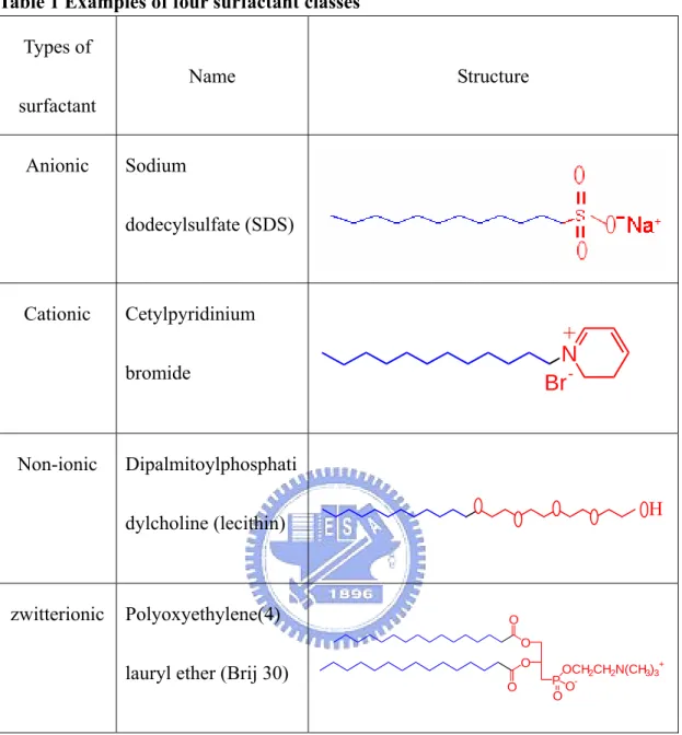
(27) 2.2 Surfactants. 2.2.1 Introduction. hydrophobic hydrophilic. Fig.8 Surfactant structure. Surfactants are amphiphile molecules which consist of two distinct groups; one is the hydrophilic (or head) group and the other hydrophobic (or tail) group (see Fig.8). Amphiphile surfactants preferentially adsorb at an interface, i.e. liquid/air, and reduce the interfacial tension. Regarding the hydrophilic groups, surfactants are primarily classified into four classes: anionic, cationic, nonionic and zwitterionic in nature. Examples of these four classes surfactant are shown in Table 1.. 17.
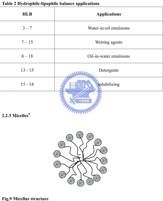
(28) Table 1 Examples of four surfactant classes Types of Name. Structure. surfactant Anionic. Sodium dodecylsulfate (SDS). Cationic. Cetylpyridinium. + N Br -. bromide. Non-ionic. Dipalmitoylphosphati H. dylcholine (lecithin). zwitterionic. Polyoxyethylene(4). O O O. lauryl ether (Brij 30). O. OCH2CH2N(CH3)3+ P OO. 2.2.2 Hydrophile-lipophile balance (HLB)18. In 1949s, Griffin proposed a concept of hydrophile-lipophile balance of surfactants which was used to assess the quantitative measure of the amphiphilicity of surfactants. These numbers were introduced to facilitate the selection of particular compound in a specific application. HLB number ranges from 1-40: the higher is the. 18.
(29) value the stronger is the hydrophilicity in character. Table 2 lists the applications of surfactants with different HLB number.. Table 2 Hydrophile-lipophile balance applications HLB. Applications. 3–7. Water-in-oil emulsions. 7 – 15. Wetting agents. 8 – 18. Oil-in-water emulsions. 13 - 15. Detergents. 15 - 18. solubilizing. 2.2.3 Micelles9. Fig.9 Micellar structure. When surfactant molecules reach a certain concentration, they aggregate and. 19.
(30) form micelles in aqueous solution, and this concentration is called critical micellar concentration (CMC). In the micellar structures, the hydrophilic groups of surfactants are exposed to aqueous phase, and the hydrophobic groups are orientated toward interior, forming oily core (Fig.9). When micellization occurs, some physical properties of solution, i.e. osmotic pressure and surface tension, have sudden change in measurement (Fig.10).. Property value. Osmotic pressure. solubilization. Surface tension. CMC Concentration of surfactant. Fig.10 Physical properties change in micellar solution. 20.
(31) One of the most important changes or properties of the micellar system is their solibilization of species in the solution. For aqueous micelles, solubilization is closely related to the hydrophobic and amphipathic properties of the solubilizate. Basically, the loci of the solubilization can be divided into three sites with description as follows and is schematically depicted Fig.11:. 1. 3. 2 Fig.11 Loci of solubilization of substances in micelles. 1. Adsorption at the micellar surface, i.e. at the micelle-water interface. 2. In the palisade layer between the hydrophilic head groups. 3. In the inner core of the micelles. Generally, the inner core of the micelles is considered the locus of solubilization for non-polar solubilizate such as n-alkanes. Solubilizate molecules of relatively high polarity such as alcohols are believed to penetrate between the palisade layers of which the polar functional groups (e.g. -OH) are able to expose to water19. However, some literature also presented the conflictions for molecules, such as 21.
(32) aromatic hydrocarbons. These molecules are non-polar but they are located at the micellar surface20, 21. Additionally, it should be emphasized that like the surfactant monomers the solubilizates are not rigidly fixed in the micelles; not only can it move about within the micelles, but also it is in constant dynamic equilibrium with the bulk aqueous phase22.. 2.2.4 Factors influencing solubilization9,23. 1.. Effect of the structure of the surfactant Generally, the amount of solubilizate increases with increasing size of the micelles. For example, increasing the alkyl chain length that causes an increase in the aggregation number of the micelles is expected to increase the solubilization capacity.. 2.. Effect of the structure of solubilizates The polarizability of solubilizates plays a crucial part. Other factors that affect the solubilization extent are chain length and branching, molecular shape and size.. 3.. Effect of added electrolytes Since electrolytes enable to diminish the mutual repulsion of the ionic head groups of surfactants, addition of electrolytes to the ionic surfactant solution 22.
(33) would decrease the CMC and increase the micellar size. 4.. Effect of addition of non-electrolytes Normally, the presence of hydrocarbons increases the solubilization of polar compounds as the swelling of the micelles allows the penetration to the palisade layers of more polar compounds. On the other hand, the solubilization of polar compounds such as long-chain alcohols, amines and fatty acids, appears to increase the solubilization of hydrocarbons.. 2.3 Spectral analysis in micellar systems. To understand the nature of the local microenvironments of micellar systems is important for evaluating the structure and properties of the micelles, and their ability to solubilize compounds. Several techniques such as NMR24, small angle neutron scattering (SANS) and Fourier transform pulsed field gradient spin echo (FT-PGSE)25 have been proposed to investigate the characteristics of the micellar system. Also some literature has proposed using spectral analysis, e.g. ultraviolet (UV) spectrometry19, 26, 27, 28, to examine solubilizate in the micellar system. Among all these available methods, we have chosen the UV spectral analysis as our experimental method. Molecular absorption in the UV/vis region of the spectrum is dependent on the 23.
(34) electronic structure of the molecule in its environment. Wavelength shift as well as the change of their vibrational fine structures has usually been observed while the analyte is solubilized in micellar solution. Generally, the similarities of absorption spectra of analytes in micellar solutions and in low-polarity solvents can be interpreted as the analytes staying in the low-polar environment in the micelles. On the other hand, we can also assume that the location of the analytes is near or at the micelle-water interface if analytes in micellar solutions and in polar solvents have similar absorption spectra9. For example, by comparing UV spectra of ethylbenzene obtained in heptane, water and 0.1 M SDS a micellar solution (in Fig.12), one may conclude that the analytes should probably exist in non-polar solubilization site in the core region29.. Fig.12 Spectral of ethylbenzene: upper continuous line, heptane; dashed line, 0.1 M sodium dodecyl sulfate; lower continuous line, water29. 24.
(35) However, some cautions should be considered when spectral data in micellar solutions are analyzed. For example, some contradictory outcomes were observed while naphthalene in micellar solutions was analyzed spectroscopically30. Although a general way for evaluating the spectral effects upon micellization is not available, practical applications based on the wavelength shifts and the absorptivity coefficient variations have been reported9. Furthermore, when UV spectra used in analyzing the locations of analytes in micellar system, it is necessary to define certain terms as following: 1. red (or bathochromic) shift : the shift of absorption to longer wavelength. 2. blue (or hypsochromic) shift : the shift of absorption to shorter wavelength. However, to explain this wavelength shift it is necessary to consider solvent-solute interactions, which depend on the polar and non-polar nature of both the solvent and solute. For examples, the n →π* transitions of single chromophoric groups such as the carbonyl group which are characterized by the hypsochromic shift observed with an increase in solvent polarity. However, for theπ→π* transitions of enones, it usually undergoes a bathochromic shift as the polarity of the solvent is increased31. It is well known that the micellar phase is less polar than the aqueous phase, therefore spectra shifts to longer wavelength (red shift) also occurs from pre-micellar to micellar phase19.. 25.
(36) Chapter 3 Experimental Section. 3.1 Apparatus. Fig.13 Photograph of the HSCCC instrument. The HSCCC instrument employed was a Model CCC-1000 high-speed countercurrent chromatography (Fig.13) designed and constructed by Pharma-Tech Research Company in Baltimore Maryland, USA. The multilayer coil separation column was prepared by winding a 54 m long, 1/8 inch O.D. and 1/16 inch I.D. tefzel tube directly onto the holder forming multiple coiled layers with a total capacity of 108 mL. The stationary phase retention volume was about 81~83%. And the revolution speed of the apparatus was regulated at 800 rpm. The solvent was pumped. 26.
(37) into the column with a Series II Digital HPLC Pump at the flow rate of 2 mL/min. The temperature controller was able to adjust within ± 1℃ and was manufactured by Mong Lien Company in Hsinchu. Continuous monitoring of the effluent was achieved with a BIO-RAD (CA, USA) model 1801 UV/Vis detector. A manual sample injection valve with a 100 μL loop was used to introduce the sample into the column.. 3.2 Reagents. Steroids ((+)-4-cholesten-3-one (CS)( >95%), progesterone (PS) (>98%), Δ4 –androstene-3,17-dione (AS) (>99% ), β-estradiol (ED) (>97%), testosterone (TS) (>99%), ergosterol (ES) (>95%), cholesterol acetate (CA) (>95%)) were purchased from TCI (Tokyo, Japan). Esters (butyl acetate (99%), propyl acetate (98%), ethyl acetate (99.5%), methyl acetate (99%)) were HPLC grade and purchased from Acros Organics (New Jersey, USA). Ketones (2-hexanone (98%), 2-pentanone (97%), 2-butanone (99%)) were GC grade and purchased from TCI (Tokyo, Japan). Benzaldedyde (99%) and acetophenone (98%) were from Lancaster (Lancashire, UK) and Sigma Chemical (St. Louis, USA), respectively. The anionic surfactants used were water soluble sodium 1-heptanesulfonate (SHS) (C7H15SO3- Na+) (98%), sodium 1-hexanesulfonate. (SXS). (C6H13SO3- Na+). (98%),. sodium. 1-nonasulfonate. (C9H19SO3- Na+) (98%), and cationic surfactant cetyltrimethyl ammonium bromide (C19H42 N+Br-) (99%) were purchased from TCI (Tokyo, Japan). Sodium n-dodecyl sulfate (C12H25SO4- Na+) (99%) was from Sigma Chemical (St. Louis, USA). All organic solvents (n-hexane, methanol, acetonitrile, acetone) were HPLC grade which 27.
(38) obtained from Mallinckrodt Baker (Philipsburg, USA), and deionized water from Milli-Q plus (Bedford, MA). Sample solutions were prepared by dissolving the analytes in the upper phase of the solvent system used for separation, at a suitable concentration according to the UV detection required. The critical micellar concentration (CMC) of SHS was measured 300mM in our laboratory32. By calculation, the CMC of SHS was 670mM9.. 3.3 Preparation of n-hexane/ surfactant-containing water solvent system. The following solvent system was prepared: n-hexane/ surfactant -containing water (3:1) mixture was thoroughly shaken and equilibrated in a separatory funnel at room temperature, and the two phases were separated overnight before use. The liquid on the top portion in the funnel is called upper phase, while the bottom portion called lower phase.. 28.
(39) 3.4 HSCCC separation procedure. Monitor Pump Detector. High-speed Waste. Countercurrent Chromatography. Mobile Phase. Fig.14 Schematic diagram of experimental set-up. A schematic diagram of our experimental set-up was shown in Fig.14. The high-speed countercurrent chromatography was performed as follows: the multilayer coiled column was first filled entirely with the lower phase. The upper phase was then pumped into the tail end of the column at a flow rate of 2.0mL/min, while the apparatus was run at 800 rpm. After hydrodynamic equilibrium was reached, indicated by a clear mobile phase eluting at the head outlet, 100μL of sample solution was injected through the sample port. The effluent from the head end of the column was continuously monitored with a UV detector. After all desired peaks were eluted. 29.
(40) the rotation and elution were stopped. Then, the column contents were collected into a graduated cylinder by N2 flushing. The retention of the stationary phase relative to the total column capacity was computed from the volume of the stationary phase collected from the column.. 3.5 Ultraviolet/visible spectroscopy. All absorption spectra of the samples in the ultraviolet range were measured by an Agilent 8453 UV-Vis spectrophotometer (Waldronn, Germany) at room temperature. The instrument was a diode-array-based UV-Vis spectrophotometer. The cell used for the ultraviolet spectroscopy was 1-cm path-length quartz cuvette.. 30.
(41) Chapter 4 Results and Discussion. 4.1 Separation results. 4.1.1 Separation of steroids. We have mentioned in the introduction section that organic two-phase system is not a suitable solvent system in CCC due to its difficulty to attain a satisfying K value. In order to solve this problem, we attempted to use n-hexane/surfactant-containing water solution to mimic this solvent system. With the lower phase as the stationary phase, and the upper phase as the mobile phase, this solvent system has been used to separate three steroids in CCC. In addition, when the mobile phase was consumed, we could just directly continue our experiment with fresh n-hexane, and without pre-saturated with the surfactant-containing water solution. Even though this system has demonstrated the feasibility of separating hydrophobic compounds32 previously in our laboratory, some progressions are still needed to improve its separation efficiency and capability. Also, we found that the elution order of these analytes (CS→PS→AS) was incompatible with our expectation (AS→PS→CS). At first, we assumed the analytes were well partitioned between the organic mobile phase and the hydrophobic cores of the micellar phase, therefore the more hydrophobic of the compound the slower it should be eluted out. However, the 31.
(42) outcomes conflicted with our assumption, i.e. the more hydrophobic of the compound the faster it was eluted out. Accordingly, we would investigate not only the efficiency and capability of this solvent system, but also the separation mechanism.. 4.1.1.1 Length of surfactant alkyl chain. Fig.15 Chromatogram of three steroids in the solvent system of n-hexane : SXS (830mM) = 3 :1. The detection wavelength is 230nm. (CS: (+)-4-cholesten-3-one(200 mg/L), PS: progesterone (300 mg/L), AS: Δ4 –androstene-3,17-dione (400 mg/L)). Surfactant SHS with linear alkyl chain of seven carbons has been used to separate three steroids in CCC in our previous work32. Other surfactants of different chain length were also tried in order to investigate their separation effect in CCC. At first, longer alkyl chain surfactants that were more than seven carbons, e.g. sodium 32.
(43) 1-nonasulfonate, SDS (sodium n-dodecyl sulfate), and CTAB (cetyltrimethyl ammonium bromide), had been used. However, these longer surfactants tended to adsorb at the aqueous-organic interface and caused emulsification in our solvent system. Therefore these longer-chain surfactants were not feasible in our studies. Then the surfactant of shorter alkyl chain, i.e. sodium 1-hexanesulfonate, was also tried. In Fig.15, it shows this shorter-chain surfactant has successfully separated three steroids in CCC. Additionally, the elution order was also same as in using the SHS micellar solvent system. Therefore, from the above results we found shorter alkyl chain surfactants were more feasible than longer-chain surfactants in CCC.. 4.1.1.2 Concentration of SHS. Solubilization of analyte is related to the formation of micelles. Once micelles are formed, the solubility increases with increasing surfactant concentration (see Fig. 10). Our experimental results agreed with this phenomenon. As surfactant concentration approached to CMC (~300mM), the unresolved peaks (CS and PS) started splitting into two peaks32. The increase of the retention times of PS and AS revealed that solubilities of these two steroids in micellar solution were elevated. As the concentration of surfactant was increased to 400mM, a complete resolving of the peaks was finally achieved. However, we tried to extend its potential to separate more 33.
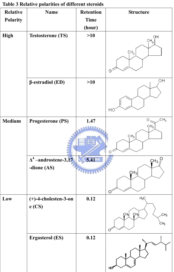
(44) steroids. So, straightforwardly we increased the surfactant concentration to 600mM and hoped that by enhancing its separation time, the efficiency could also be increased simultaneously. The chromatogram is shown as fig.16.. Fig.16 Chromatogram of three steroids in the solvent system of n-hexane : SHS (600mM) = 3 : 1. The detection wavelength is 230 nm. (CS: (+)-4-cholesten-3-one(200 mg/L), PS: progesterone (300 mg/L), AS: Δ4–androstene-3,17-dione (400 mg/L)). The steroids used in our study can be categorized into three relative polarities according to their retention times: high, medium, and low (Table 3).Steroids that were not detected after 10 hours elution were considered as high polarity; medium polarity. 34.
(45) Table 3 Relative polarities of different steroids Relative Polarity High. Medium. Name. Retention Time (hour). Testosterone (TS). >10. β-estradiol (ED). >10. Progesterone (PS). 1.47. Δ4 –androstene-3,17 -dione (AS). 5.41. Structure. CH 3. O. CH 3. O. Low. (+)-4-cholesten-3-on e (CS). 0.12. H3C. CH3. CH3. CH3 CH3. O. Ergosterol (ES). 0.12. 35.
(46) Cholesterol acetate (CA). 0.12. steroids ranged from 1 hour to 6 hours, and low polarity steroids were about 0.12 hour (or no retention). A steroid is characterized by its carbon skeleton with four fused rings (Fig.17). If we categorized the relative polarities of steroids according to their functional groups which were attached to these rings, we found these groups have some relations with their retention times. The high-polarity steroids are those with at least one hydroxyl group and not eluted out after 10 hours. In fact, the steroids eluted out ranging from 1 to 6 hours are those with a carbonyl group attached to ring D. These compounds possess indeed medium polarity according to their structures. The low ones which are those with a long alkyl chain attached to ring D, and their retention time were less than 0.12 hour (or virtually non-retained).. Fig.17 The basic structure of steroid 36.
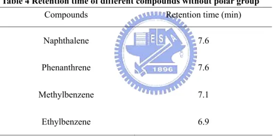
(47) In Fig.16, the latter two compounds (PS and AS) belonged to the medium polarity steroids. However, neither high- nor low-polarity steroid was able to result in a reasonable retention factor (k’). Since high-polarity steroids were unfavorably soluble in n-hexane and preferably retained in the micellar stationary phase, whereas the low-polarity steroids preferably dissolved in n-hexane and resulted in very short retention time in our solvent system. In the beginning, we thought that when the separation time was lengthened, more steroids might be separated. However, the results showed we were unable to separate more steroids using this solvent system.. 4.1.2 Other compounds except steroids. Initially, when we chose steroids as our target compounds in this solvent system, their molecular structures, such as size, polarity and so on, were not critically considered. However, we suspected the interaction between steroids and micellar core was not just affected by its weak hydrophobic attraction, its steric hindrance might also be another factor in this system23. In addition to steroids, we then tried other compounds of very low and medium polarities respectively. (a) Small compounds with very low polarity We then chose compounds of very low polarity in order to increase the hydrophobic interaction with the non-polar micellar core. In the beginning, we tried some 37.
(48) polyaromatic hydrocarbons (PAHs), such as naphthalene and phenanthrene, which were more hydrophobic compared with the steroids. However, no obvious retention was observed for these compounds (Table 4). After that we tried two alkyl benzenes, i.e. methylbenzene and ethylbenzene; also no retention was observed. According to these results, small compounds of very low polarity were unable to be separated in our solvent system.. Table 4 Retention time of different compounds without polar group Compounds. Retention time (min). Naphthalene. 7.6. Phenanthrene. 7.6. Methylbenzene. 7.1. Ethylbenzene. 6.9. (b) Small compounds with moderate polarity We then chose small compounds with moderate polarity as our target compounds in the SHS micellar solvent system, and the followings were their separation results in CCC.. (i) Aryl group compounds 38.
(49) Fig.18 Chromatogram of (1) acetophenone and (2) benzaldehyde with concentration of 30μg/mL respectively and in the solvent system of n-hexane : SHS (600mM) = 3 : 1. The detection wavelength is 240 nm.. (ii) Ester. Fig.19 Separation chromatogram of (1) butyl acetate (2) propyl acetate (3) ethyl acetate and (4) methyl acetate with concentration of 30μg/mL respectively and in the solvent system of n-hexane : SHS (600mM) = 3 : 1. The detection wavelength is 230 nm. 39.
(50) (iii) Ketones. Fig.20 Separation chromatogram of (1) 2-hexanone (2) 2-pentanone and (3) 2-butanone with concentration of 20μg/mL respectively and in the solvent system of n-hexane : SHS (600mM) = 3 : 1. The detection wavelength is 280 nm.. From the above results, it shows the separation capability of our micellar solvent system toward the moderate polarity and small-sized molecules. From the retention time trend, we found the polarities of the compounds played a crucial role. In addition, compounds with small difference in polarity cannot be completely resolved (see Fig.19).. 40.
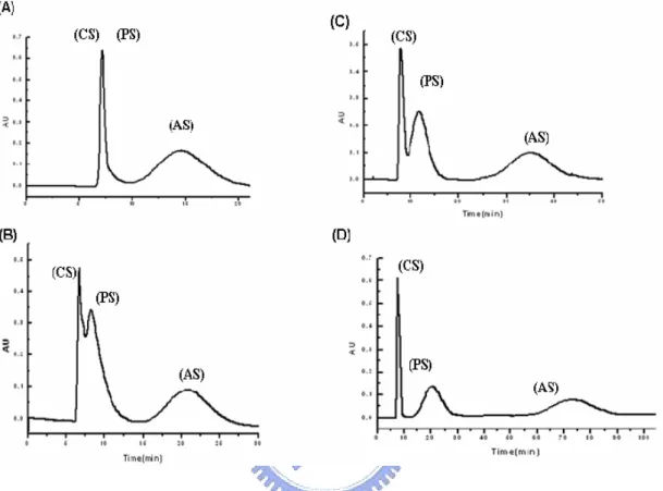
(51) 4.2 Separation mechanism. Fig. 21 Separation results of three steroids (CS, PS, AS) under different concentration of SHS32 (A) 200mM (B) 300mM (C) 350mM and (D) 400mM.. Referring to the previous work in this laboratory (see Fig. 21), although SHS concentration had not reached CMC (200 mM), this micellar solvent system still enabled to separate at least two steroids. While the surfactant concentration was increased to 400 mM, this solvent system finally enhanced its efficiency and successfully separated three steroids. As generally known, when surfactant is added into aqueous solution, the polarity of the aqueous solution will become lower. Even the concentration of the surfactant was below CMC, it still showed the separation 41.
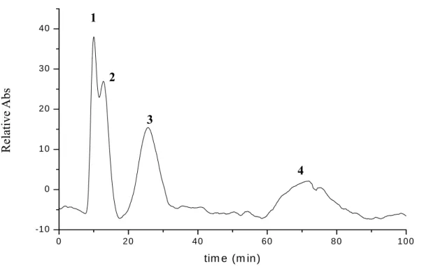
(52) capability. It can be explained that since the polarity of this pre-micellar solution was decreased to certain extent to provide adequate partition for the two steroids between the two phases; thus to resolve CS and AS peaks. However, when the concentrations of the surfactant became well above the CMC, the separation mechanism could not be simply explained by the polarity factor. When micelles are formed, the large surface-charge densities of these aggregates interact with highly polar solutes through strong ion-dipole interactions19. Accordingly, when the surfactant concentration reaches CMC the separation of three steroids in CCC was no longer just dependent on the polarity effect but was also dependent on the ion-dipole interaction. We then tried to separate four esters under 200 mM concentration of SHS and evaluate these compounds under the pre-micellar solvent system. Fig. 22 shows four ester compounds separated under pre-micellar solvent system. The elution order of this pre-micellar system was similar to that of using the 600 mM micellar system. According to this outcome, we can propose the same mechanism as in the separation of steroids (CS and AS) in which the separation might mainly depend on the decreasing polarity of pre-micellar solution.. 42.
(53) 1 40. 2. 20. 3. mv. Relative Abs. 30. 10. 4 0. -10 0. 20. 40. 60. 80. 100. tim e (m in). Fig. 22 Separation chromatogram of (1) butyl acetate (2) propyl acetate (3) ethyl acetate and (4) methyl acetate with concentration of 30μg/mL respectively and in the solvent system of n-hexane : SHS (200mM) = 3 : 1. The detection wavelength is 230 nm. The three steroids that were successfully separated (see in Fig. 16) have a general structure shown in Fig. 23. The functional group R makes the major difference in the polarity of these steroids. With this elution order, we found that our earliest mechanism assumption, i.e. steroids might penetrate into the micellar core and caused the separation in CCC32, might be incorrect. R. O Fig.23 The general structure of the steroid separable in our present work. 43.
(54) Fig. 24 shows the spectra of two steroids (PS and AS) in water, methanol and n-hexane at room temperature. It is clear from the spectra that in the aqueous solution the band shifted toward longer wavelength as compared to those in methanol and n-hexane. To explain this wavelength shift it is necessary to consider solvent-solute interactions or the dielectric effect of the solvent in the absence of any specific solvent-solute interactions19. The π → π* transitions of enone, such as mesityl oxide, was reported to undergo a bathochromic shift with increasing dielectric constant of the solvent31. Since the steroids of interest possessed enone groups, and the same effect was also observed in our case; therefore we could conclude the wavelength shifts of steroids were mainly influenced by this group. Since the micellar phase is less polar than the neat water phase, the absorbance summits should shift to shorter wavelength (hypsochromic shift) from pre-micellar to micellar phase. And the effect was indeed observed in our studies (Table 5).. 44.
(55) (a) 0. 6. 0. 5. Relative Abs. 0. 4. 0. 3. 0. 2. 0. 1. -0. 1 190. 200. 210. 220. 230. 240. 250. 260. 270. 280. 290. wav el en g t h (n m). Relative Abs. (b). 0.5. 0.4. 0.3. 0.2. 0.1. -0.1 205. 215. 225. 235. 245. 255. 265. 275. 285. Wavelength (nm). Fig.24 UV absorption of (a) Δ 4 –androstene-3,17-dione (400mg/L), and (b) progesterone (300mg/L)in H2O (. ), methanol (. 45. ) and n-hexane (. )..
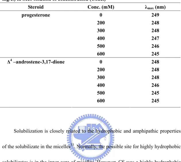
(56) Table 5 λmax (nm) of progesterone (10 mg/L) and Δ4 –androstene-3,17-dione (10 mg/L) in SHS solution of concentration (Conc.) Steroid. Conc. (mM). λmax (nm). progesterone. 0. 249. 200 300 400 500 600. 248 248 247 246 245. 0 200 300 400 500 600. 248 248 248 246 245 245. Δ4 –androstene-3,17-dione. Solubilization is closely related to the hydrophobic and amphipathic properties of the solubilizate in the micelles33. Normally, the possible site for highly hydrophobic solubilizates is in the inner core of micelles. However, CS was a highly hydrophobic solubilizate but was totally insoluble in our micellar solution even with the surfactant concentration as high as 600mM. Since CS was highly soluble in n-hexane, therefore, we tried to use this solvent to carry CS penetrating into micelles. A solution of CS in n-hexane (200mg/L) was prepared. Six μL of this solution was added to 10 mL micellar solutions of different surfactant concentrations and stirred for ~ 15 mins. Fig. 25 shows n-hexane was able to act as a “carrier” for bringing CS into the micellar solution. A red shift of the absorbance was observed. It must be noted that this. 46.
(57) absorbance measurement was achieved by directly solubilizing CS into the micellar solutions and not through partitioning between two phases. However, CS was favorably soluble in the mobile phase; therefore, no retention of CS was observed in the CCC separations.. Fig.25 UV absorption of (+)-4-cholesten-3-one in n-hexane (200mg/L) which was added 6μL into 10 mL micellar solutions of different SHS concentrations and stirred about 15 mins.. According to the literature19, some workers explained this red shift phenomenon revealed solute penetration into the micellar inner core. Then the absorbance measurements of PS and AS should also show similar red shifts as CS if these two compounds truly penetrated into the micellar cores because all three steroids shared similar molecular structure and their chromophores were all enones. Thus, we also 47.
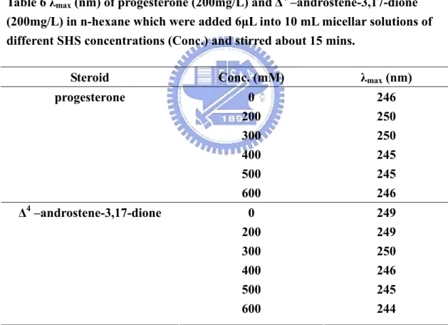
(58) investigate the absorptions of the other two steroids (PS and AS). The outcomes are shown in Table 6. However, hypsochromic shifts instead were observed. It implied these two steroids were solubilized in other locations of micellar solution and not in the inner core. Also, we have tried other PAHs, and their absorptions were increased when surfactant concentration was increased. But no obvious band shift was observed in our experiments.. Table 6 λmax (nm) of progesterone (200mg/L) and Δ4 –androstene-3,17-dione (200mg/L) in n-hexane which were added 6μL into 10 mL micellar solutions of different SHS concentrations (Conc.) and stirred about 15 mins. Steroid. Conc. (mM). λmax (nm). progesterone. 0 200 300 400 500 600. 246 250 250 245 245 246. Δ4 –androstene-3,17-dione. 0 200 300 400 500 600. 249 249 250 246 245 244. Now, only two other probable locations needed to be considered. Solubilizate are also believed to possibly penetrate into the palisade layers of which the polar functional group exposes outwardly to water and the non-polar group orients inwardly 48.
(59) to the inner core19. If CS was able to penetrate in palisade layers, its lower polarity alkyl chain should orient inwardly, while the higher polarity enone group should orient outwardly. However, we have mentioned that no absorption was detected when powder of CS was directly added and thoroughly stirred in micellar solution. Apparently, this molecule could not penetrate into the palisade layer. With regard to the other steroids (PS and AS), since they are constituted by two polar functional groups (enone and carbonyl group) at each side, therefore, none of these groups is able to orient inwardly to the inner core. Accordingly, they would not be able to penetrate into the palisade layers of the micelles. Since PS and AS are unable to stay either in the inner cores or in the palisade layers, we would propose that these compounds might locate at the micellar surfaces. When ionic surfactant concentration is above the CMC, they aggregate and carry high formal charge at the micelle/water interface. With this high local electrostatic field, these steroids may locate at the micellar surface via ion-dipole interaction with the charged groups of the micelles. From the chromatogram (Fig.16), the result also agreed with this argument, i.e., steroids with higher polarity was eluted out slower. Therefore, we believe that these two steroids interacted with the micellar system through ion-dipole attraction in CCC. As to those small polar molecules, even though we did not use the same. 49.
(60) spectroscopic method to deduce the mechanism as for steroids, we found that the chromatograms could be explained in same manner (Figs. 18-20), i.e., with higher polarity, slower the analytes were eluted out. Therefore, we believe the ion-dipole interaction also influenced the small polar compounds in this micellar system, and caused the compounds partitioned only between n-hexane and the micellar surface and not inside the micellar core.. 50.
(61) Chapter 5 Conclusions After a series of experiments, we have successfully characterized a new solvent system: n-hexane/surfactant-containing water in CCC. Even though we were unable to enhance the separation capability of steroids in the present, separation of the other samples helped us to understand more about this solvent system. According to the results and absorbance spectra, we believe that the analytes partitioned between the mobile and stationary phases via two possible interactions. While the surfactant concentrations were lower than the CMC, the partition occurred mainly due to the hydrophobic interaction because the polarity of the lower phase was decreased by the added surfactant molecules. However, while the concentrations became higher than the CMC, a stronger ion-dipole interaction dominated. In the future we may try surfactants with other ionic groups, such as carbonate group, phosphate group to modify the solvent systems. In. conclusion,. we. have. proposed. a. new. solvent. system:. n-hexane/surfactant-containing water that shows some advantages over the organic two-phase system in CCC. Elution using this new system was quite stable, possibly due to the fact that the two phases were quite immiscible. Applications using this new solvent system are yet to be explored.. 51.
(62) References 1. A. Berthod, “Counter-current Chromatography, The Support-free Liquid Stationary Phase”, Comprehensive Analytical Chemistry, Vol. XXXVIII, Elsevier, Amsterdam, 2002. 2. F.Q. Yang; T.Y. Zhang; R. Zhang; Y. Ito, “Application of analytical and preparative high-speed countercurrent chromatography for separation of alkaloids from Coptis chinensis Franch”. J. Chromatogr. A. 1998, 829, 137. 3. F.Q. Yang; Y. Ito, “Preparative separation of Lappaconitine, ranacontine, N-deacetyllappaconitine and N-deacetylranaconitine from crude alkaloids of sample Aconitum sinomontanum Nakai by high-speed countercurrent chromatography”. J. Chromatogr. A. 2002, 943, 219. 4. H. Oka; K. Harada; Y. Ito; Y. Ito, “Separation of antibiotics by countercurrent chromatography”. J. Chromatogr. A. 1998, 812, 35. 5. M. Knight; M.O. Fagarasan; K. Takahashi; A.Z. Geblaoui; Y. Ma; Y. Ito, “Separation and purification of peptides by high-speed countercurrent chromatography”. J. Chromatogr. A. 1995, 702, 207. 6. K. Shinomiya; T. Komatsu; T. Murata; Y. Kabasawa; Y. Ito, “Countercurretn chromatographic separation of vitamins by cross-axis coil planet centrifuge with eccentric coil assemblies”. J. Liq. Chrom. & Rel. Tech. 2000, 23(9), 1403. 7. Y. Wei; T. Zhang; G. Xu; Y. Ito, “Application of analytical and preparative high-speed countercurrent chromatography for separation of lycopene from crude extract of tomato paste”. J. Chromatogr. A. 2001, 929, 169. 8. Y. Ito, “Golden rules and pitfalls in selecting optimum conditions for high-speed countercurrent chromatography”. J. Chromatogr. A. 2005, 1065, 145. 9. E. Pramauro; E. Pelezetti; “Surfactants in analytical chemistry, applications of organized amphiphilic media”, Comprehensive Analytical Chemistry, Vol. XXXI, Elsevier, Amsterdam, 1996. 10. N.B. Mandava; Y. Ito, “Countercurrent chromatography, theory and practice”, Vol. 44, Marcel Dekker Inc., New York, 1988. 11. W.D. Conway, “Countercurrent chromatography, apparatus, theory, and applications”, VCH publishers Inc, New York, 1990. 12. Y. Ito; W.D. Conway, “High-speed Countercurrent Chromatography”, Vol. 132, Wiley-Interscience, 1996. 13. Y. Ito; J. Sandlin; W.G.. Bowers, “High-speed preparative countercurrent chromatography with a coil planer centrifuge”. J. Chromatogr. 1982, 244, 247. 14. W.D. Conway; Y. Ito, “Resolution in countercurrent chromatography”. J. Liq. 52.
(63) Chromatogr. 1985, 8 (12), 2198. 15. H. Oka; Y. Ikai; J. Hayakawa; K. Harada; M. Suzuki; A. Shimizu; T. Hayashi; K. Takeba; H. Nakazawa; Y. Ito, “Separation of ivermectin components by high-speed countercurrent chromatography”. J. Chromatogr. A. 1996, 723, 61. 16. P.A. Albertsson, “Partition of cell particles and macromolecules”. Wiley-Interscience, New York, 1986. 17. K. Shinomiya; Y. Kabasawa; K. Yanagidaira; H. Sasake; M. Muto; T. Okada; Y. Ito, “Protein separation by nonsynchronous coil planet centrifuge with aqueous-aqueous polymer phase systems”. J. Chromatogr. A. 2003, 1005, 103. 18. 廖明隆, 界面化學與界面活性劑, 文源書局。 19. B. Naseem; A. Sabri; A. Hasan; S.S. Shah, “Interaction of flavoids within organized molecular assemblies of anioinic surfactant”. Colloids and Surfaces B, 2004, 35, 7. 20. J.H. Fendler; L.K. Patterson,“Comment on solubilization of benzene in aqueous cetyltrimethylammonium bromide measured by differential spectroscopy”. J. Phys. Chem., 1971, 75, 3907. 21. S.J. Rehfeld, “Solubilization of benzene in aqueous sodium dodecyl sulfate solutions measured by differential spectroscopy”. J. Phys. Chem. 1970, 74, 117. 22. M. Almgren; F. Grieser; J.K. Thomas, “Dynamic and static aspects of solubilization of neutral arenes in ionic micellar solutions”. J. of the Am. Chem. Soc., 1979, 101, 279. 23. 趙承琛, 界面科學基礎, 復文書局, 台灣台南, 1990 年。 24. R. Bacaloglu; C.A. Bunton; G. Cerichelli; F. Ortega, “NMR study of the location of bromide ion and methyl naphthalene-2-sulfonate in cationic micelle: relation to reactivity”. J. Phys Chem. 1989, 93, 1490. 25. G..M. Forland; J. Samseth; M.I. Gjerde; H. Hoiland; A. Jensen; K. Mortensen, “Influence of alcohol on the behavior of sodium dodecoylsulfate micelles”. J. Colloid Interface Sci. 1998, 203, 328. 26. S.J. Rehfeld, “Solubilization of benzene in aqueous sodium dodecyl sulfate solutions measured by differential spectroscopy”. J. Phys. Chem. 1970, 74, 117. 27. S.S. Shah; G.M. Laghari; K. Naeem, “A spectroscopic study of hemicyanine dyes in anionic micellar solutions”. Thin Solid Films, 1999, 346, 145. 28. J. Yang, “Interaction of surfactants and aminoindophenol dye”. J. Colloid and Interface Sci., 2004, 274, 237. 29. J.R. Cardinal; P. Mukerjee, “Solvent effects on the ultraviolet spectra of benzene derivatives and naphthalene, identification of polarity sensitive spectral characteristics”. J. Phys. Chem., 1978, 82, 1614. 30. J.H. Fendler and E.J. Fendler, “Catalysis in Micellar and Macromolecular 53.
(64) Systems”. Academic Press, New York, 1975. 31. R.M. Sillverstein; G.C. Bassler, “Spectrometric identification of organic compounds”. John Wiley & Sons Inc., New York, 1974. 32. 張郁培, “使用正己烷/含界面活性劑水溶液之溶劑系統以逆流層析分離類 固醇化合物", 國立交通大學, 碩士論文,民國九十三年七月。 33. K.L. Mittal; “Micellization, solubilizaiton, and microemulsions”, Volume 1, Plenum Press, New York, 1977.. 54.
(65)
數據
+5
相關文件
了⼀一個方案,用以尋找滿足 Calabi 方程的空 間,這些空間現在通稱為 Calabi-Yau 空間。.
特性:高孔率、耐 130C 高壓滅菌,透光性佳,以 RI 值 1.515 之溶液潤濕過 濾膜即可用顯微鏡觀察過濾膜上的粒子。灰分含量 0.002 mg/cm 2 。一般用來
• ‘ content teachers need to support support the learning of those parts of language knowledge that students are missing and that may be preventing them mastering the
Let T ⇤ be the temperature at which the GWs are produced from the cosmological phase transition. Without significant reheating, this temperature can be approximated by the
Courtesy: Ned Wright’s Cosmology Page Burles, Nolette & Turner, 1999?. Total Mass Density
support vector machine, ε-insensitive loss function, ε-smooth support vector regression, smoothing Newton algorithm..
專案執 行團隊
• But Monte Carlo simulation can be modified to price American options with small biases..
