行政院國家科學委員會專題研究計畫 成果報告
連結差分空時調變與渦輪碼應用於正交分頻多工系統
計畫類別: 個別型計畫
計畫編號: NSC92-2213-E-011-100-
執行期間: 92 年 08 月 01 日至 93 年 07 月 31 日 執行單位: 國立臺灣科技大學電機工程系
計畫主持人: 白宏達
計畫參與人員: 宋經天、黃文隆
報告類型: 精簡報告
處理方式: 本計畫可公開查詢
中 華 民 國 93 年 10 月 4 日
Concatenation of Differential Space-Time Modulation and Turbo Codes for OFDM Systems
Hung-Ta Pai
Institute of Communication Engineering National Taipei University San Shia, Taipei, 237 Taiwan
Abstract − In this paper, we present a
broadband wireless communication system. This system is designed using updated techniques.
These techniques consist of space-time coding, turbo codes, and OFDM. Moreover, a differential detection scheme is also included such that neither channel estimation nor channel equalization is required. Soft output of the detection is derived for turbo decoding. At a throughput of 1 bit per symbol, BER of the system can reach 10-5 while Eb/N0 is less than 7 dB.
Keywords: space-time coding, turbo code,
differential detection, space-time block coding, OFDM, soft output, broadband wireless communicationsI. INTRODUCTION
Because of strong demand for broadband wireless communications, a large amount of researchers have involved in this area. Many significant results have been reported. These results include the improvement of existing approaches and the inventions of new methods.
Among them, space-time coding (STC) [1], turbo codes [2], and orthogonal frequency division multiplexing (OFDM) techniques [3]
have attracted lots of attention. It is time to use these techniques to design a high data-rate wireless communication system.
STC was proposed by Tarokh et al. It is designed by jointly considering channel coding (time diversity), modulation, and antenna (space) diversity. Bitstream is coded into several sets of codes using trellis coding and then each set of
the codes is transmitted by a specific antenna.
Although STC performs very well, its computational complexity is relatively high. To improve this problem, Alamouti proposed space- time block coding (STBC) [4]. He used block coding techniques instead of the trellis coding.
Moreover, only two transmit antenna and one receive antenna were used. STBC is simple but its performance is not as good as the performance of STC. Since the block coding in STBC only includes two symbols, the trellis coding in STC has better time diversity than the block coding does.
To improve the performance of STBC, channel coding is required. In [5], different channel coding approaches, including turbo codes, turbo Bose-Chaudhuri-Hocquenghem (BCH) codes, turbo trellis-coded modulation (TCM), TCM, and convolutional codes, are combined with STBC, respectively. The results show that the turbo code with STBC is the best combination in reasonable complexity. Furthermore, the combination also has better performance than STC.
In STBC or STC, one-tap known channel response (i.e., known flat-fading channel) is assumed. Although the concatenation of STBC and the turbo code performs extremely well, this assumption sets a limit on applications of the concatenation in real world. In wireless communications, the assumption is not practical because of multipath effect. To obtain one-tap channel response in the multipath environment, OFDM [6] can be used. Moreover, differential coding [7] techniques can be applied for signal detection without knowledge of the channel. The
technique combined with STBC is called differential STBC (DSTBC).
In this paper, we propose a communication system using turbo codes, DSTBC, and OFDM.
The system architecture is described in Section II. Since soft input is required for decoding of the turbo code, we provide an approach to derive it in Section III Section IV describes simulation environment and presents simulation results.
Finally, some conclusions are made in Section V.
II. THE SYSTEM ARCHITECTURE
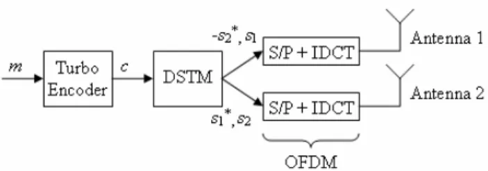
Figure 1: The transmitter architecture
Figure 1 shows the transmitter architecture.
OFDM is done by serial to parallel transform (S/P) and inverse discrete Fourier transform (IDCT). Bitstream of message m is encoded by the turbo encoder. The coded bits c of the encoder then is sent to the differential space-time modulation (DSTM) block as shown in the following figure:
Figure 2: The DSTM block
Two complex scalars at symbol time t, AtN+k
and B
tN+k, are obtained through properly mapping from b consecutive bits [7]; and⎥ ⎦
⎢ ⎤
⎣ + ⎡−
⎥ ⎦
⎢ ⎤
⎣
= ⎡
⎥ ⎦
⎢ ⎤
⎣
⎡
+ + +
+ + + +
+ + +
*
*
, 1 , 2
, 2 , 1
) 1 ( , 2
) 1 ( , 1
k tN
k tN k tN k tN
k tN k tN N t k
N t k
s B s s
A s s
s
where (·)* denotes the complex conjugate transpose and N is the number of subcarriers in the OFDM system and. DN
block delays input
signals for N unit times. At two symbol times, 2t and 2t+1, of the OFDM system, the following two symbol vectors are transmitted:
T N tN tN
tN t
T N tN tN
tN t
s s
s s
s s
s s
] [
] [
1 , 2 1
, 2 , 2 , 2
1 , 1 1
, 1 , 1 , 1
− + +
− + +
=
=
L L
where (·)T denotes the transpose. At the symbol time 2t, s1,t and s2,t are transmitted by the first antenna and the second antenna, respectively. At the symbol time 2t+1, the first antenna and the second antenna transmit -s2,t* and s1,t*, respectively.
If the guard interval of the OFDM system is long enough, the multipath effect can be reduced to one-tap channel response. For the two antennas, the response for the kth sub-channel can be represented by a 2x1 vector,
⎥⎦
⎢ ⎤
⎣
=⎡
k k
k h
h
, 2 ,
h 1
The received signals of the sub-channel k at the symbol times 2t and 2t+1:
k t k k tN k tN k
t
k t k k tN k tN k t
n s
s r
n s
s r
, 1 2 ,
1 ,
2 ,
1 2
, 2 ,
2 ,
1 , 2
*]
* [
] [
+ +
+ +
+ +
+
−
=
+
=
h h
where n2t,k and n2t+1,k are additive white Guassian noise (AWGN). The receiver architecture then can be designed as follows:
Figure 3: The receiver architecture
If the channel does not change during four continuous symbol times, AtN+k
and B
tN+k can be estimated in the differential space-time demodulation (DSTD) block as follows [7]:(2)
*]
[
*]
[ '
(1)
*]
[
*]
[ '
, 1 2 , 2 , 3 2 , 2 2
, 1 2 , 2 , 3 2 , 2 2
k t k t k t k t k tN
k t k t k t k t k tN
r r
r r B
r r r
r A
+ +
+ +
+ +
+ +
−
•
=
•
=
2
where (․) denotes the inner product operator.
For simplifying notation, we will use A′ and B′
instead of AtN+k′ and BtN+k′.
Inverse mapping has to be done to decide coded bits c1
’ c
2’
… cb’ from A’ and B’. However, since
the turbo decoder requires soft input, a soft decision method for c’ is necessary. According to the principle of turbo decoding [2], we have to estimate the following function:(3) ) ' ,'
| 0 ' (
) ' ,'
| 1 ' log ( )
' ⎟⎟
⎠
⎜⎜ ⎞
⎝
⎛
=
= = (
Λ p c A B
B A c c p
i i i
It is not easy to perform the estimation. In the next section, a simplified function is provided.
The computational complexity of the turbo decoder in [2] is very high. Several sub-optimal decoding algorithms with lower complexity have been proposed. Among them, the Max-Log- MAP algorithm [9] has much lower complexity with a little bit performance loss. Therefore, we will use the Max-Log-MAP algorithm in the decoding process.
III. SOFT OUTPUT OF DSTD
Without loss generality, we let k=0, t=0, and⎥⎦
⎢ ⎤
⎣
⎡
= −
*
*
1 2
2 1
h h
h H h
and then, by simplifying subscripts of variables, rewrite (1), (2) as
[ ]
(4) ] [
] )[
(
*]
[
*]
[
*]
[
*]
[ ]' ' [
2 2 2 1
0 1 3 2 1 0 3 2
B
A
N
N B A h h
r r r r r r r r B A
+ +
=
−
•
•
=
where* ]
* ][
* [
* ] [
* ]
* [
* ]
* [
] [
1 0 3 2
0 , 2 0 , 1 3
2
1 0 , 2 , 1
n n n n
s s H n n
n n H s s
N
A N N+ +
=
and
* ]
* ][
* [
* ]
*
* [
* ]
* [
* ]
* [
] [
0 1 3 2
0 , 1 0 , 2 3
2
0 1 , 2 , 1
n n n n
s s H n n
n n H s s
N
B N N− +
− +
−
=
Under higher signal-to-noise ratio (SNR) conditions, the last terms of NA and NB can be ignored. For NA, the coefficients of the noise terms n0* and n1are
*,
*
*,
*
*
*
,
*
* ,
2 1 1 2 2 2 1 1
, 2 1 , 1 2 , 2 2 , 1 1
s h s h s h s h
s h s h s h s
h
N N N N− +
− +
respectively. For NB, the coefficients of the noise terms n0, n1*, n2, and n3* are
2 2 1 1 2 1 1 2
, 2 2 , 1 1 , 2 1 , 1 2
,
*
*
, ,
*
*
s h s h s h s h
s h s h s h s
h
N N N N−
−
−
+ +
−
respectively. Notice that the coefficients in NA
have the same magnitudes, but with different order, as the ones in NA. Moreover, because n0,
n
1, n2, and n3 are AWGN, NA and NB are AWGN with the same variance.For further simplification, NA and NB are assumed to be independent and each coded bit is individually dealt with. Only the closest vector [A B] to [A′ B′], such that the bit equals to 1 (0), is chosen to compute the probability of ci′=1 (ci′=0). Therefore, (3) can be simplified as
(5)
) (
' )
( '
) (
' )
( ' ) '
2 1 2 2 2 1 2
1 2 2 2 1
2 0 2 2 2 1 2
0 2 2 2 1
B h h B A h h A
B h h B A h h A c
i+
−
− +
−
−
+
− + +
−
≈ ( Λ
where [A0
B
0] and [A1B
1] are the closest vectors to [A’ B’] such that the coded bits equal to 0 and 1, respectively. Since h1 and h2 are unknown, we set |h1|2+|h2|2=2 and have(6) ' '
' '
) '
'(ci = A−A0 2+ B−B0 2− A−A1 2− B−B12 Λ
In later simulations, we will show that this setting has no performance loss, even has little performance gain.
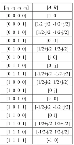
We use an example to explain the calculation of Λ′(ci
′). For b=4, A and B can be obtained from
four coded bits according the mapping table in Table 1 [7]. The number of bits per modulation symbol equals to 2.[c
1c
2c
3c
4] [A B]
[0 0 0 0] [1 0]
[0 0 0 1] [1/2+j/2 -1/2+j/2]
[0 0 1 0] [1/2-j/2 -1/2-j/2]
[0 0 1 1] [0 -1]
[0 1 0 0] [1/2+j/2 1/2-j/2]
[0 1 0 1] [j 0]
[0 1 1 0] [0 -j]
[0 1 1 1] [-1/2+j/2 -1/2-j/2]
[1 0 0 0] [1/2-j/2 1/2+j/2]
[1 0 0 1] [0 j]
[1 0 1 0] [-j 0]
[1 0 1 1] [-1/2-j/2 -1/2+j/2]
[1 1 0 0] [0 1]
[1 1 0 1] [-1/2+j/2 1/2+j/2]
[1 1 1 0] [-1/2-j/2 1/2-j/2]
[1 1 1 1] [-1 0]
Table 1: The mapping table for b = 4
There are 16 possible vectors for [A B]. If
A′=0.2-0.3j and B′=0.3+0.2j, then
] 2 / 2 / 1 2 / 2 / 1 [ ] [
] 0 1 [ ] [
1 1
0 0
j j
B A
B A
+
−
=
=
and6 . 0
2 / 2 / 1 2 . 0 3 . 0
2 / 2 / 1 3 . 0 2 . 0
0 2 . 0 3 . 0 1 3 . 0 2 . 0 ) ' '
2 2
2 2
0
=
−
− +
−
+
−
−
−
− + +
−
−
= ( Λ
j j
j j
j j
c
IV. SIMULATION RESULTS
We use the same turbo encoder and interleaving method as the ones in UMTS [10]. The turbo encoder includes two identical convolutional encoders whose octal generator polynomial is (13, 15). The length of a block is 4096. The output bits of the convolutional encoders arepunctured such that the code rate of the turbo encoder equals to 1/2. The puncturing pattern is 10, 01. At the end of the turbo encoder, a random interleaver is used. The length of the interleaver is also 4096.
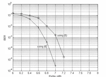
Table 1 then is used as the mapping table in DSTM. Thus, the throughput of the system is 1 bit per modulation symbol (BPS). The number of subcarriers in OFDM is 256. There are five paths for each transmit antenna to the receiver. The power of the path is randomly generated. We simulate the system using 2500 blocks. (6) is used to calculate the soft output of DSTD. The results are shown in Figure 4:
Figure 4: BER vs. E
b/N
0when 1 BPS
After five iterations, the bit error rate (BER) reaches 10-5 while Eb/N0 is around 6.9 dB.
Compared with the results in [5], the performance loss is around 5.5 dB. The loss comes from the differential detection (near 4 dB [7]), the shorter length of the interleaver, the Max-Log-MAP algorithm, the approximation of the soft output.
In Figure 5, (5) is used instead of (6). We can see that using (6) is better than using (5) by 0.2 to 0.3 dB after five iterations.
V. CONCLUSIONS
We have developed a broadband wireless communication system using the updated
4
techniques: turbo codes, STC, and OFDM.
Channel state information is not required because of the differential detection. When Eb/N0 equals to 7 dB, BER is lower than 10-5 at a throughput of 1 BPS.
Figure 5: Difference between using (5) and (6) after 5 iterations
REFERENCES
[1] V. Tarokh, N. Seshadri, and A. Calderbank,
“Space–time codes for high data rate wireless communication: Performance criterion and code construction,” IEEE
Trans. Inform. Theory, vol. 44, pp. 744-765,
Mar. 1998.[2] C. Berrou and A. Glavieux, “Near optimum error correcting coding and decoding:
Turbo-codes,” IEEE Trans. Comm., vol.44, pp. 1261-1271, Oct. 1996.
[3] H. Sari, G. Karam, and I. Jeanclaude,
“Transmission techniques for digital terrestrial TV broadcasting,” IEEE
Communication Magazine, vol. 42, pp. 100–
109, Feb. 1995.
[4] S. Alamouti, “A simple transmit diversity technique for wireless communications,”
IEEE J. Select. Areas Comm., vol. 16, pp.
1451-1458, Oct. 1998.
[5] T. H. Liew and L. Hanzo, “Space-time codes and concatenated channel codes for wireless communications,” Proc. of the
IEEE, vol. 90, pp. 187-219, Feb. 2002.
[6] D. Agrawal, V. Tarokh, A. Naguib, and N.
Seshadri, “Space–time coded OFDM for high data-rate wireless communication over wide-band channels,” Proc. IEEE Vehicular
Technolgy Conf., Ottawa, Canada, pp. 2232-
2236, May 1998.[7] V. Tarokh and H. Jafarkhani, “A differential detection scheme for transmit diversity,”
IEEE J. Select. Areas. Comm., vol. 18, pp.
1169-1174, Jul. 2000.
[8] G. Bauch, “Concatenation of space–time block codes and Turbo-TCM,” Proc. IEEE
Int. Conf. Comm., Vancouver, Canada, pp.
1202-1206, 1999.
[9] P. Robertson, P. Hoeher, and E. Villebrun,
“Optimal and sub-optimal maximum a posteriori algorithms suitable for turbo decoding,”
European Trans. on Telecommun., vol. 8, pp. 119-125, Mar.-Apr.
1997.
[10] ETSI, “Universal mobile telecommunications system (UMTS);
multiplexing and channel coding (TDD),”
European Telecommunications Standard, TS 125 222 V5.3.0, Dec. 2002.
連結差分空時調變與渦輪碼應用於正 交分頻多工系統
白宏達
摘要−−在本文中,結合了最新的三項通訊技 術,設計出一寬頻無線通訊系統。此三種技
術為:空時碼、渦輪碼、以及正交分頻多工技
術。再加上差分偵測的使用,使得無論是通 道估計或是通道等化皆不再需要。由於濄輪 解碼需要軟性輸入,我們推導了差分偵測的 軟性輸出計算方式,並加以簡化。在每調變
符號傳送 1 位元的情況下,以低於 7 dB 的
SNR 達成位元錯誤率低於 10-5之效能。
關鍵字:空時碼、渦輪碼、差分偵測、空時塊 狀碼、正交分頻多工、軟性輸出、寬頻無線 通訊