行政院國家科學委員會專題研究計畫 成果報告
雙金屬單層觸媒於奈米金屬粒子上之沉積及其對有機小分 子催化特性之研究(第 3 年)
研究成果報告(完整版)
計 畫 類 別 : 個別型
計 畫 編 號 : NSC 97-2221-E-011-075-MY3
執 行 期 間 : 99 年 08 月 01 日至 100 年 07 月 31 日 執 行 單 位 : 國立臺灣科技大學化學工程系
計 畫 主 持 人 : 黃炳照
公 開 資 訊 : 本計畫涉及專利或其他智慧財產權,2 年後可公開查詢
中 華 民 國 100 年 11 月 24 日
中 文 摘 要 : 雙金屬核-殼結構奈米粒子因其具有多機能性、高催化性、磁 性、熱穩定性及光學特性,漸漸成為具有潛力應用之材料,
但其在設計上之基本原理目前仍舊不明。本研究發展一動力 學控制之自催化化學法,能廣泛地夠用來合成雙金屬核-殼結 構奈米粒子。其原理為將可自我犧牲的極薄銅層於動力學控 制條件下,沉積於尺寸穩定之貴金屬核上,進而以金屬置換 反應(redox-transmetallation)將具有活性之極薄殼層沉積 於核上。相較於以熱力學控制的欠電位沉積法,本研究之方 法具有可量產性高品質的核-殼結構奈米顆粒,例如:Pd@Pt, Pt@Pd, Ir@Pt, and Ir@Pd,且不需加入額外的還原劑及(或) 電化學處理。而本團隊也對具有商業化潛力的 Pd@Pt 奈米顆 粒進行了系統性的研究,如臨場 X 光吸吸光譜、電化學紅外 線光譜、穿透式電子顯微鏡以及電化學技術,特別是於燃料 電池操作中極為重要的氧氣還原反應(oxygen reduction reaction, ORR)。結果顯示,雙金屬 Pd@Pt 奈米顆粒相對於 單金屬的奈米顆粒而言,能夠顯著地提升電化學催化活性。
中文關鍵詞: 動力控制, 自催化, 核-殼, 鈀@白金, 白金極薄層 英 文 摘 要 :
英文關鍵詞:
1
行政院國家科學委員會補助專題研究計畫 ■成果報告 □ 期中進度報告
雙金屬單層觸媒於奈米金屬粒子上之沉積及其對有機小分子 催化特性之研究 (3/3)
計 畫 類 別 : ■ 個 別 型 計 畫 □ 整 合 型 計 畫 計畫編號:NSC 97-2221-E-011 -075 -MY3
執行期間: 99 年 08 月 01 日至 100 年 07 月 31 日
計 畫 主 持 人 : 黃 炳 照 教 授
成果報告類型(依經費核定清單規定繳交):精簡報告
■
完整報告本 成 果 報 告 包 括 以 下 應 繳 交 之 附 件 :
□ 赴 國 外 出 差 或 研 習 心 得 報 告 一 份
□ 赴 大 陸 地 區 出 差 或 研 習 心 得 報 告 一 份
□ 出 席 國 際 學 術 會 議 心 得 報 告 及 發 表 之 論 文 各 一 份
□國際合作研究計畫國外研究報告書一份
處理方式:除產學合作研究計畫、提升產業技術及人才培育研究計畫、
列管計畫及下列情形者外,得立即公開查詢
□涉及專利或其他智慧財產權,□一年□二年後可公開查詢 執行單位:台灣科技大學化工系
中 華 民 國 100 年 11 月 24 日
2
行政院國家科學委員會專題研究計畫報告
金屬單層觸媒於奈米金屬粒子上之沉積及其對有機小分子催 化特性之研究 (3/3)
Deposition of bimetallic monolayer catalysts on metallic nanoparticles and their electrocatalytic activity for small organic molecules (3/3)
計畫編號:NSC 97-2221-E-011 -075 -MY3 執行期限:99 年 08 月 01 日至 100 年 07 月 31 日 主持人:黃炳照 教授 國立台灣科技大學化工系
摘要雙金屬核-殼結構奈米粒子因其具有多機 能性、高催化性、磁性、熱穩定性及光學特 性,漸漸成為具有潛力應用之材料,但其在 設計上之基本原理目前仍舊不明。本研究發 展一動力學控制之自催化化學法,能廣泛地 夠用來合成雙金屬核-殼結構奈米粒子。其原 理為將可自我犧牲的極薄銅層於動力學控制 條件下,沉積於尺寸穩定之貴金屬核上,進 而以金屬置換反應(redox-transmetallation)將 具有活性之極薄殼層沉積於核上。相較於以 熱力學控制的欠電位沉積法,本研究之方法 具有可量產性高品質的核-殼結構奈米顆粒,
例如:Pd@Pt, Pt@Pd, Ir@Pt, and Ir@Pd,且 不需加入額外的還原劑及(或)電化學處理。而 本團隊也對具有商業化潛力的 Pd@Pt 奈米顆 粒進行了系統性的研究,如臨場 X 光吸吸光 譜、電化學紅外線光譜、穿透式電子顯微鏡 以及電化學技術,特別是於燃料電池操作中 極為重要的氧氣還原反應(oxygen reduction reaction, ORR)。結果顯示,雙金屬 Pd@Pt 奈 米顆粒相對於單金屬的奈米顆粒而言,能夠 顯著地提升電化學催化活性。
關鍵字:動力控制, 自催化, 核-殼, 鈀@白金, 白金極薄層
ABSTRACT. Although bimetallic core@shell structured nanoparticles (NPs) are achieving prominence due to their multifunctionalities and exceptional catalytic, magnetic, thermal, and optical properties, the rationale underlying their design remains unclear. Here we report a
kinetically-controlled autocatalytic chemical process, adaptable for use as a general protocol for the fabrication of bimetallic core@shell structured NPs, in which a sacrificial Cu- ultrathin layer is autocatalytically deposited on a dimensionally-stable noble-metal core under kinetically-controlled conditions, which is then displaced to form an active ultrathin metal- layered shell by redox-transmetallation. Unlike thermodynamically-controlled under-potential deposition (UPD) processes, this general strategy allows for the scaling-up of production of high quality core-shell structured NPs, without the need for any additional reducing agents and/or electrochemical treatments, some examples being: Pd@Pt, Pt@Pd, Ir@Pt, and Ir@Pd. Having immediate and obvious commercial potential Pd@Pt NPs have been systematically characterized by in situ X-ray absorption, electrochemical-FTIR, transmission electron microscopy, and electrochemical techniques; both during synthesis, and subsequently during testing in one particularly important catalytic reaction, namely the oxygen reduction reaction which is pivotal in fuel cell operation. It was found that the bimetallic Pd@Pt NPs exhibited a significantly enhanced electrocatalytic activity, with respect to this reaction, in comparison with their monometallic counterparts.
KEYWORDS. Kinetically-controlled, autocatalytic, core-shell, Pd@Pt, Pt-ultrathin layer.
3 INTRODUCTION. The bulk fabrication of
advanced bimetallic nanostructures with exceptional catalytic,1-2 magnetic,3-4 thermal,5 and optical6-7 properties is a prerequisite for their wide applicability in nanotechnology.
Bimetallic core-shell nanostructures, made with an active-metal shell supported on another metal as a core element, are emerging as one of the most promising solutions able to address these requirements. Such bimetallic core-shell nanostructures with enhanced nanoscale properties are of interest due to their potential as highly efficient catalysts,8-9 magnetic components for ultrahigh density memory devices,8-9 and sensors in the biomedical field.10 Among bimetallic core-shell nanostructures, Pt- ultrathin layered shells on the surface of a dimensionally stable M metal core (McorePtultrathin- shell, where: M is the noble and 3d-transition metals) NPs are achieving prominence due to their multifunctionalities and enhanced properties that can be broadly exploited for those applications.11-13 The most widespread role of platinum is as a catalyst, particularly in the automobile industry, petrochemical industry, fuel cells, biosensors, etc.14 As Pt is tremendously expensive, it is highly beneficial to reduce the amount of Pt. The McorePtultrathin-shell
NPs comprise a very low Pt content in their outer ultrathin layer shell, are one of the best solutions to addressing this issue: an approach that can cutback the Pt cost while enhancing catalytic activity.
Although these bimetallic core-shell nanostructures are of significance, the conventional synthetic approaches have not been successful in producing high quality core- shell NPs. These difficulties are due to several factors including random nucleation processes and inhomogeneous growth of the hetero- metallic component on core’s surface NPs.15 Thus, it is necessary to develop and couple new NPs synthesis methods with first-principles theoretical design, as it gives mechanistic insight into the atomistic surface chemistry governing the enhanced properties and provides the groundwork for NPs fabrication.
Here we report a first-principal theoretical guided synthesis and characterization of selected core-shell NPs and demonstrate their unique properties using an oxygen reduction reaction (ORR) - a key reaction for the practical implementation of hydrogen fuel cells. We
additionally examine the general applicability of the designed strategy for the other core-shell NPs, e.g. Pt@Pd, Ir@Pt, and Ir@Pd. The PdcorePtultrathin-shell NPs were chosen as a primary example since Adzic et al.,12 found that the ORR activity of a Pt-layered shell supported on Au(111), Rh(111), Pd(111), Ru(0001), and Ir(111), follows a volcano-type profile with respect to the center of their d-bands, with the Pt-layered shell on Pd(111) showing the highest activity, and thereby could address the principal drawbacks in this application, namely the sluggish kinetic and high Pt-loading associated with the ORR.16-17
Similarly, the fabrication of these PdcorePtultrathin-shell NPs is an ongoing challenge. In established redox transmetallation approach,9 the Pd-core NPs are directly refluxed with the Pt-salt precursor, often leading to the formation a dense array of Pt dendritic branches, rather than a uniform Pt-ultrathin layer shell.18-19 This outcome has been attributed to the small lattice mismatch (~ 0.77 %) between these two metals, as the spontaneous epitaxial growth of Pt on the Pd core is thermodynamically favored.20-21 When these Pd NPs undergo a redox reaction with the Pt ions, which have a higher equilibrium potential, the unwanted dissolution of the Pd NPs also takes place. Toshima et al.,22-23 protected the surface of the Pd core with a sacrificial hydrogen layer before contacting with Pt ions. This redox approach, in which the adsorbed hydrogen layer was oxidized by Pt ions, prevents the dissolution of the Pd core.
However, there difficulty in producing a Pt- ultrathin layer remains a challenging task, since the previously formed Pt layer is still active towards hydrogen and so can create additional thick Pt-layers.
Adzic et al.,12-13,24-25
used the redox displacement of previously deposited Cu, by the under-potential-deposition (UPD) of ad-atoms on a Pd surface, to form Pt monolayered NPs.
UPD involves the deposition of an ad-atom on a foreign-metal substrate at a potential more positive than that predicted by the Nernst equation. Applying this potential makes the strength of the interactions between the ad-atom and the substrate greater than among the ad- atoms, during spontaneous deposition under thermodynamically-controlled conditions.
However, since the synthesis was carried out electrochemically on a glassy carbon electrode,
4 the resulting quantity of Pt monolayered
electrocatalyst was limited to a few tens of μg.26 To scale-up production, we started from first principles using DFT to search for a non- electrochemical way of depositing a Cu-ultrathin layer on a Pd/C core, which we could displace to form a Pt-ultrathin layer shell. The present approach, which overcomes the Cu-UPD process’s limited production capacity, utilizes the strong reducing ability of the metal- hydride/adsorbed hydrogen on the palladium’s surface.27 Here the electrons from the sacrificial oxidation of the adsorbed hydrogen layer on Pd are used for the reduction of the Cu salt and the deposition of a Cu-ultrathin layer on the Pd core’s surface. It is well-known that hydrogen is easily adsorbed and split on the surface of noble metals to form hydrides. This hydride/adsorbed hydrogen has a strong reducing ability, suggesting very low equilibrium potential.22-23 When metal ions having a higher equilibrium potential (e.g. Cu2+, Cu2+ + 2e- → Cu, 0.34 V) approach to the adsorbed hydrogen, they can be reduced by sacrificial oxidation of the adsorbed hydrogen resulting the deposition of Cu on the Pd surface under favorable redox condition (∆E° > 0). Since the Cu metal surface is substantially inactive toward hydrogen, there is a large barrier against Cu dissociating the hydrogen molecule, e.g. adsorbing and splitting it to form hydride. The lack of hydride on the Cu surface prevents the initiation of self- nucleation leading to the formation of a Cu- ultrathin layer on the Pd surface (PdcoreCuultrathin- shell structure). Our DFT modeling study clearly predicts this sort of kinetically-controlled behavior (Fig. 1). The Cu-ultrathin layer is sacrificially oxidized by Pt redox transmetallation, to form Pt-ultrathin layer on Pd.
This autocatalytic process has several advantages: (1) no additional reducing agent and electrochemical treatments are needed (2) layer deposition occurs only on the core’s surface (3) the original size and shape of the core are maintained, and (4) significant quantities of the core-shell NPs can be prepared.
Figure 1. (A) DFT model of the top-view of Pd(111) slab system, together with (B) its corresponding contour maps and (C) potential energy profile for the dissociative adsorption of hydrogen, in comparison with that of Cuultrathin- shellPdcore(111) slab system (D-F).
RESULTS AND DISCUSSION. We have used DFT modeling to illustrate the relationship between the metal’s surface with its adsorbate, and various catalytic processes,28-30 e.g. to show the way hydrogen adsorbate dissociates on Pd(111) and Cuultrathin-shellPdcore(111) surfaces. In Fig. 1A, the Pd(111) system was modelled using four-layer slabs of a Pd fcc lattice, nine atoms per layer, a 3 × 3 super-cell with dimensions of 8.253 × 8.253 × 18.493 Å3, exposing the (111) facet. A similar configuration was adopted for the Cuultrathin-shellPdcore(111), with the top layer of Pd atoms being replaced with Cu atoms (Fig.
1D). Its corresponding contour map, which depicts the electron density contour of the plane cut through the Cu atom and Pd atom at the center site (Fig 1E), is clearly different from that of Pd(111) (see Fig. 1B). This, consequently, may give different energy barriers for hydrogen dissociation on these two metals surfaces.
The geometries of the adsorbed sites in each pathway and their corresponding potential energy profiles are illustrated in Fig. 1. In the initial state (I.S.), the hydrogen molecule preferentially adsorbs on three-fold sites of the Pd(111) and Cuultrathin-shellPdcore(111) slab surfaces, since these sites have the larger
5 coordination number, and thus present the most
stable sites. At the transition state (T.S.), the bond breaking of hydrogen molecules takes place given a sufficient energy. Simultaneous bond formation between the adsorbate and the substrate takes place in the final state (F.S.). We have calculated the dissociation energy barriers (Ed) involved in hydrogen bond
breaking on both the slab surfaces. The pure Pd(111) slab, has a dissociation energy barrier of only 0.08 eV, thus the Pd surface easily adsorbs and spontaneously splits hydrogen.31 The dissociation energy barrier (0.23 eV) on CumonolayerPdcore(111) surface is significantly higher, implying that the Cu-monolayer layer is inert towards hydrogen and therefore cannot form additional thick Cu layers because the process is kinetically-controlled. This contrasts with conventional thermodynamically-controlled Cu UPD processes.
This Cu-ultrathin layer then generates a Pt- ultrathin layer on Pd by redox transmetallation;
i.e. the Cu-ultrathin layer is sacrificially oxidized to generate electrons for the reduction of Pt, thereby depositing a Pt-ultrathin layer on the Pd core (see Fig. 2A). To characterize the Pd-Cu and Pd-Pt core-shell structures we performed in situ X-ray absorption (XAS) measurements,32-39 as shown in Fig. 2. XAS spectroscopy, encompassing both the X-ray absorption near- edge structure (XANES) as well as the extended X-ray absorption fine structure (EXAFS), is a powerful structural/characterization technique for investigating oxidation states and the environment surrounding an absorbing atom.
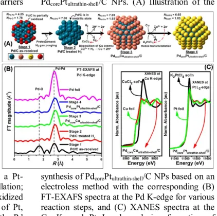
The modules of Pd k-edge of the Fourier transform (FT) obtained for all the PdcorePtultrathin- shell/C NPs reaction steps during preparation are shown in Fig. 2B. The corresponding EXAFS fitting parameters are listed in the supporting information Table S1. In stage 1, compared to the Pd foil, the transform of the commercially Pd/C NPs shows an additional peak at ~1.99 Å, attributed to the presence of a Pd-O bond, characteristic of partially oxidized Pd/C. In stage 2, this partially oxidized sample was hydrogen purged for 2 h. As a result, the peak attributed to Pd-O disappeared, while a Pd-Pd bond located at ~2.79 Å increased in intensity, indicating the Pd/C sample is in a metallic state
(Pd0). These changes correspond to coordination number changes for Pd-Pd (NPd-Pd) increasing from 4.25 to 7.08 (Table S1).
Figure 2. In situ X-ray absorption techniques used for probing the reaction mechanism of the PdcorePtultrathin-shell/C NPs. (A) Illustration of the
synthesis of PdcorePtultrathin-shell/C NPs based on an electroless method with the corresponding (B) FT-EXAFS spectra at the Pd K-edge for various reaction steps, and (C) XANES spectra at the Cu K- and Pt L3-edges during formation of PdcoreCuultrathin-shell/C and PdcorePtultrathin-shell/C NPs, respectively.
In stage 3, the Cu precursor was added and hydrogen purging continued for 6 h to form a surface Cu-ultrathin layer, as shown in the FT- EXAFS and XANES spectra. The XANES spectra at the Cu K-edge, for the 0.05 M CuCl2
solution (black line), PdcoreCuultrathin-shell/C NPs (red line), and Cu foil reference (green line) are shown in Fig. 2C-left. The XANES profile of the Cu precursor, i.e. CuCl2, exhibits a sharp peak at 8995 eV corresponding to the +2 oxidation state.38 The intensity of this sharp peak (termed a white line), attributed to the 1s
→ 4p electronic transition, is sensitive to the oxidation state of Cu. After the introduction of a Cu precursor into a suspension of hydrogen purged NPs, the white line intensity decreased gradually and reached a similar intensity to that of Cu foil, indicating the reduction of Cu2+ to Cu0. After 6 h there was a shift in the edge energy to a lower value (~ 3 eV). In addition to a white line feature, a pre-edge feature originating from the 1s → 3d transition38 is
6 observed at 8980 eV, about 12 eV below the
white line peak, which is similar to that of Cu foil. Since the pre-edge peak is a fingerprint for copper metal, its appearance suggests that a Cu- ultrathin layer in the metallic state (Cu0) had been formed. Using EXAFS-based methodology, we have shown that the structure of bimetallic core-shell NPs can be influenced by the atomic distribution between
two constituent elements.39 The same EXAFS-based
methodology was used to confirm the formation of the core- shell structure of Pd-Cu NPs. First, we calculated the total number of Pd and Cu atoms around Pd (ΣNPd-
i = NPd-Pd + NPd-Cu) and Cu (ΣNCu-i = NCu-Cu + NCu- Pd). If ΣNPd-i > ΣNCu-i then the NPs possess a Pdcore-Cushell structure. It was observed that for the NPs ΣNPd-i > ΣNCu-i and NPd-Pd > NCu-Cu > NPd- Cu (see Table S1). It has been shown that for a homogeneous system of A-B bimetallic NPs with a core composed of N atoms of A and a surface made of N atoms of B, the total coordination number for the A atom (NA-i = NA-A
+ NA-B) is greater than the total coordination for the B atom (NB-i = NB-A + NB-B).39 In this case, the interactions at equilibrium follow the order NA-A > NB-B > NA-B.39 Hence, the observed parameter relationships, ΣNPd-i > ΣNCu-i and NPd- Pd > NCu-Cu > NPd-Cu, support the Pdcore-Cushell
structural assignment for the PdcoreCuultrathin- shell/C NPs. The present method, also allows a Cu-ultrathin layer to be deposited on other highly reactive noble metal surfaces, e.g. Pt and Ir (see Fig. S2). Utilizing these two reactive metals as the core NPs, various core-shell structured NPs such as Pt@Pd, Ir@Pt, and Ir@Pd can be prepared by this general method.
Finally, the Cu-ultrathin layer was sacrificially oxidized by the Pt precursor, i.e. K2PtCl4 to form a Pt-monolayer on the Pd/C NPs via redox transmetallation. Using the same argument with a Pdcore-Cushell structure that was previously confirmed by XAS, we see in Fig. 2C-right that the XANES spectrum for the PdcorePtultrathin-shell/C NPs at Pt L3-edge is similar to that of Pt foil, indicating a Pt-ultrathin layer in metallic state (Pt0) had been formed on Pd/C surface. The
observed parameter relationship in Table S1 shows ΣNPd-i > ΣNPt-i and NPd-Pd > NPt-Pt > NPd-Pt, and confirms the Pdcore-Ptshell structure of the PdcorePtultrathin-shell/C NPs.
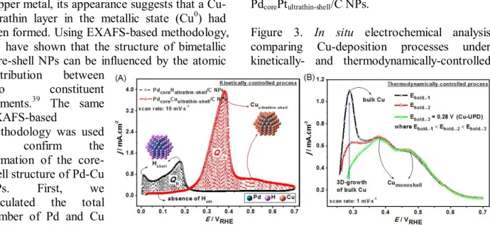
Figure 3. In situ electrochemical analysis comparing Cu-deposition processes under kinetically- and thermodynamically-controlled
conditions. (A) The stripping voltammograms of the adsorbed hydrogen-monolayer (−○−) and the adsorbed Cu-ultrathin layer (−∆−) on Pd/C NPs using an electroless method, and (B) the stripping voltammograms of the adsorbed Cu layers on Pd/C NPs using electrochemical treatments, i.e. at various applied potentials.
Electrolyte: 0.5 M H2SO4; temperature: 30°C.
We additionally performed an in situ electrochemical analysis to confirm the formation of Cu-ultrathin layered Pd/C NPs.
The stripping voltammograms of the adsorbed hydrogen and the Cu-ultrathin layer are shown in Fig. 3A. The striping voltammogram for adsorbed hydrogen on Pd/C was obtained after hydrogen adsorption (applied potential at 0.00 V), in an electrolyte solution (0.5M H2SO4) at 30 °C, the potential was scanned at 10 mV·s-1. The stripping curve for the adsorbed hydrogen shows two distinctive desorption peaks in the potential region between 0 and 0.3 V, associated with the oxidation of previously adsorbed hydrogen (2H = 2H+ + 2e-) on different Pd crystalline facets.40 This suggests that the Pd/C NPs have a strong reactivity towards hydrogen, i.e. they absorb, adsorb, split, and oxidize it to generate electrons22 that can reduce metal ions such as Cu2+ and in doing so deposit only a Cu-ultrathin layer on the Pd/C NP’s surface. The existence of this Cu-ultrathin layer correlates well with the stripping voltammogram of the PdcoreCuultrathin-shell/C NPs
7 (Figure 3A). The stripping voltammogram was
produced as follows: the Pd/C NP’s surface was initially treated with hydrogen in a 0.5 M H2SO4
electrolyte solution. Next CuSO4 (0.01 M) was added and the hydrogen purge was continued to ensure that sufficient hydrogen was adsorbed on the NPs to reduce the Cu2+ ions to form the sacrificial Cu-ultrathin layer.
During the above formation of sacrificial Cu- ultrathin layer, hydrogen is probably absorbed first, and then spontaneously diffuse out to the surface of Pd surface, and subsequently consumed once that Cu2+ ions are introduced into the solution, as the ratio of the electron valence of Cu2+-to-e- (from dissociated hydrogen) is 2:1. Thus, it is important to constantly purge the hydrogen gas during the synthesis, ensuring a sufficient amount of electrons flow from the dissociated hydrogen atoms to complete the layer deposition of Cu atoms and form the Cu ultra-thin layer. The situation is different if the hydrogen is not constantly purged, in which case the generated electrons from the dissociation hydrogen would be insufficient to form a complete Cu ultrathin layer.
The Cu2+ ions displaced all the adsorbed hydrogen from the NPs’ surfaces, which is apparent from the suppression of the hydrogen desorption peaks (Fig. 3A). The reduction and deposition of the corresponding Cu2+ ions to form a Cu-ultrathin layer, appears as a strong desorption peak located at ca. 0.38 V.25 In previous study, Adzic et al.25 located the stripping Cu-bulk deposition peak, for agglomerated Cu, at a much lower onset potential, 0.21 V; which is different from the value found for the Cu-ultrathin layer presented here.
From Fig. 3, we also calculated the ratio between the stripping Cu and H charges (QCu/QH). This determines whether, for this present method, it is possible to form a well- ordered Cu-ultrathin layer on the NPs surface, without the three-dimensional (3D) growth of bulk Cu. To quantify QH and QCu, similar calculations to those reported by Green et al.,41 have been used. The QCu/QH ratio was found to be about 2, a condition where the copper atoms adsorb on Pd metal surface at the same sites as hydrogen to form a well-ordered Cu-ultrathin layer,41-42
The cyclic voltammograms (CVs) for the Cu- ultrathin layer stripping as a function of deposition time are shown in the supplementary Fig. S3. For each stripping, the first CV cycle depicts the stripping curve of the adsorbed Cu atoms on the Pd/C NPs. During the forward step in this first CV cycle, [typically after 6h of deposition (Fig S3-E)], the peak characteristic of bulk absorbed, and subsequent adsorbed hydrogen atoms (Hads) was suppressed due to the presence of the adsorbed Cu-ultrathin layer (ca. 0.38 V), whereas a peak corresponding to additional growth of Cu-bulk layers was not observed. This Cu-ultrathin layer formation was maintained, and importantly no additional growth of Cu-bulk was formed, even after the reaction was extended up to 8h (Fig. S3-F). On the second sweep, performed after stripping Cu, the voltammograms mirrored those observed for Pd/C NPs (i.e. the absence of adsorbed Cu).
These results emphasize the viability of the present method in achieving only a Cu-ultrathin layer deposition on a Pd core surface.
For comparison we conducted a parallel study in which the Cu layers were deposited on a Pd/C surface using an electrochemical (UPD) method, in which holding potentials were employed, to deposit Cu layers in a thermodynamically- controlled reaction. A Cu-monolayer can be formed at a holding potential of 0.28 V (Ehold.-3), as indicated with black arrows (Fig. 3B).
However, the holding potential associated with this Cu-UPD monolayer must be determined carefully, otherwise it may form uncompleted Cu-UPD monolayer and/or an additional bulk Cu deposits.41 For example, a slight change in the holding potential to a lower value, e.g. Ehold.- 1 and Ehold.-2, triggers the growth of additional bulk Cu, as indicated by the strong peak located at ca 0.28 V.
For the reduction reaction of Cu2+ + 2e- → Cu(s) at a standard condition, the bulk-Cu(s) will be deposited at the equilibrium potential (EbulkCu) of 0.3402 V, in accordance with the Nernst equation:
Cu Cu0 ln Cu2
bulk C
nF E RT E
(1)
Where: E = 0.3402 V, R = 8.31441 J⋅moleCu0 -
1⋅K-1, F = 96484.6 C⋅mole-1, CCu2= 1 M, n = 2, at temperature (T) of 298 K. In general, when
8 the Cu2+ concentration is less than under
standard condition ( CCu2 = 1 M), the equilibrium will shift to the left. This means that the equilibrium potential (EbulkCu) for the bulk- Cu deposition will shift to negative. Our experiments in the present study used a Cu- solution at the concentration, i.e. CCu2= 0.01 M and temperature, T = 303 K (30 C), which leads to bulk-Cu deposition at the equilibrium potential (EbulkCu) of 0.28 V. It is noteworthy that the peak associated with the bulk-Cu deposition in Fig. 3B, which is located at 0.28 V, matches that from predicted Nernst equation.
The same Pd/C catalyst was also used to perform a kinetically-controlled Cu-ultrathin layer deposition (Fig. 3A and Fig. S3): it was found that a strong desorption peak associated with the Cu ultra-thin layer was located at ca.
0.38 V, similar with that of a thermodynamically Cu-UPD process (Fig. 3B).
The present kinetically-controlled method achieves the formation of a Cu-ultrathin layer and overcomes the problem of the 3D-growth of bulk Cu associated with the thermodynamically- controlled electrochemical method. In our previous study,43 two principle reaction mechanisms were proposed to account for the autocatalytic reduction process, the first is chemical mechanism while the second is an electrochemical mechanism. In the chemical mechanism, there are two proposed explanations, the first is the “atomic hydrogen mechanism” proposed by Brenner and Riddle, while the second is the “hydride ion mechanism”
proposed by Hersch. In this chemical mechanism, a kinetically-controlled reaction is envisioned to take place because the Pd surface is the only catalytically active site for the adsorption of hydrogen and/or the hydride that can be used for reducing and depositing Cu atoms, whereas the pre-deposited Cu atoms are not an active site for this mechanism and thus restrict the growth of Cu-layers on this pre-deposited Cu surface.
This sort of kinetically-controlled reaction in the chemical mechanism is also consistent with a previous discussion on DFT results in Fig. 1.
Meanwhile, if the Cu deposition is based on electrochemical mechanism, some Cu-atoms are probably also deposited on the previously formed Cu-layer since the electrons can go through everywhere in this mechanism.
However, using the DFT data presented in Supplementary Fig. S4 and Table S2, this possibility can be ruled out, since the binding energy of Pd-Cu (-8.88 eV) is much stronger than that of Cu-Cu (-5.58 eV) interaction, thus the Cu atoms preferred deposited on Pd-core surface as a Cu-ultrathin layer. This means no matter which mechanism, either the chemical or electrochemical mechanism, is involved in the process, the Cu-ultrathin layer deposition on Pd core-surface can always be obtained. It is also consistent with the experimental results.
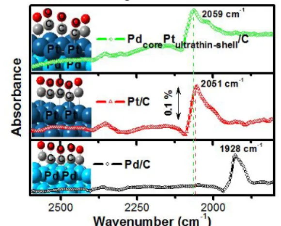
Figure 4. FTIR spectra of (−○−) Pd/C, (−∆−) Pt/C, and (−◊−) PdcorePtultrathin-shell/C NPs with the adsorption of CO at 0.05 V recorded using spectral resolution of 8 cm-1 in 0.1 M HClO4. Inset: multi-adsorbed CO molecules on the slab system constructed by the DFT modelling.
The Cu-ultrathin layer was then used to form a Pt-ultrathin layer on the Pd/C NPs, and the resulting material was characterized using in situ electrochemical-FTIR (EC-FTIR) measurements.
The FTIR spectra for the Pd/C, Pt/C and PdcorePtultrathin-shell/C NPs samples were recorded after the CO adsorption at 0.05 V (Fig. 4). A strong band at 1928 cm-1, was attributed to the stretching of bridged CO adsorbed on the surface of the Pd/C catalyst. In contrast, the Pt/C catalyst shows a strong band at 2051 cm-1, attributed to an adsorbed linear CO. These FTIR-CO spectra are consistent with those reported Pd and Pt studies.22-23 It is noteworthy that in the case of the PdcorePtultrathin-shell/C catalyst, the covering of the Pt ultrathin-shell on the Pd core gave similar results to Pt/C, where a linear CO adsorption band on the Pt ultrathin- shell appeared at 2059 cm-1. The band, associated with CO adsorbed on Pd at 1928 cm-
1, completely disappeared, proving that the Pd
9 core was completely covered by a Pt shell. In
agreement with the FTIR-CO results, our DFT modeling study based on the slab system verified the differences in the stretching frequencies of the adsorbed CO (see Table S3). After applying energy minimization, the corresponding CO adsorption energies and geometric properties are also consistent with previously reported DFT studies.28,44-45 Taken together DFT modeling and data from the FTIR-CO probe confirms that a PdcorePtultrathin-shell/C NPs structure is formed.
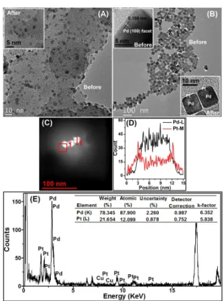
The synthesized PdcorePtultrathin-shell/C NPs were found to be spherically shaped and reasonably well dispersed with an average size of 4.5 nm (inset in Fig. 5A). The spherical shape homogeneity of the NPs was maintained by depositing the Pt atoms only on the top of the Pd core. It is important to note that the self- nucleation of additional thick Pt layer was averted and that only a uniform Pt-ultrathin layer on the Pd/C NPs surface was generated.
Recently, TEM has been successfully utilized for the characterization of a single core-shell particle, i.e. a Pd-Pt core-shell nanoplate with the edge length over 50 nm.46 However, the use of TEM is still limited by the low detector collection efficiency, especially for small bimetallic NPs (< 5 nm), where the electron dosage required for successful TEM analysis is often too high and beyond the radiation damage thresholds of the NPs47 and this may also change the NPs position. To demonstrate the viability of the present strategy, we used Pd nano-cubes (~10 nm) - adopting a method proposed by Xia et al.48 As can be seen from Fig. 5B, these cubic NPs comprising a Pd (100) facet were uniformly covered with a relatively darker colored ultrathin shell of Pt, and clearly not nucleated Pt-NPs, which also indicates the formation of well-defined core-shell structure. From the HAADF-STEM image (Fig 5C), a line-profile analysis was performed, the results presented in Fig. 5D show that the thickness of the Pt-shell was approximately 0.3 nm, which is close to the thickness of a Pt-ultrathin layer. The corresponding EDX spectrum (Fig. 5E), shows a Pd:Pt atomic ratio of around 7.27:1, which is close to that of theoretical value (8:1) for the cubical PdcorePtultrathin-shell NPs with the size of around 10 nm. In addition, STEM-EDX measurements on the Cu-monolayer on Pd nanocube were performed, see supplementary
Fig. S5. It is clear that the line-profile of this
PdcoreCuultrathin-shell cubic-sample demonstrates a similarity to the core-monolayered shell structure of the Pd-Pt system. The thickness of the Cu shell is also approximately 0.3 nm, thus indicating a Cu-ultrathin layer was formed using our strategy.
In order to examine if the redox transmetallation reaction of Cu by Pt is complete, XANES measurements particularly at the Cu K-edge were performed, and it was found that the as-prepared spherical-shaped Pd@Pt/C NPs contain only an insignificant quantity of 2.3 % Cu residues (Fig. S6) that can be easily removed by a simple electrochemical treatment, i.e. a repetitive cycling treatment for 10 cycles with scan range of 0.00 to 1.05 VRHE
at a scan rate of 0.05 V∙s-1 in 0.5 M H2SO4
electrolyte solution. This electrochemical treatment has also been employed in the surface sensitive-based techniques, i.e. cyclic voltammograms measurements. From these cyclic voltammograms (Fig. S7A), we did not find any trace of Cu-residues, since the anodic and cathodic peak currents, at a potential range of approximately 0.3 - 0.6 V, corresponding to the presence of Cu were not observed. These findings indicate that the redox transmetallation process with subsequent minor electrochemical treatments is exceptionally effective in
10 replacing the Cu-layer to form a Pt-layer on the
Pd core. A similar observation was also made by Adzic et al.,24 who also employed an electrochemical treatment, i.e. a linear potential sweep with the scan range up to 1.00 VRHE, after the redox-transmetallation reaction of Cu by Pt. They also found that the Cu-layer can be completely displaced by this combined redox transmetallation and subsequent electrochemical processing. To give a clear evidence of the viability of the present strategy, we strictly performed TEM-EDX measurements using Cu- free grids (i.e. Mo-grid), for the sample of the prepared spherical-shaped Pd@Pt/C NPs and electrochemically treated Pd@Pt/C NPs. It is noteworthy that our findings in EDX analyses are in a good agreement with those our findings on XANES and electrochemical measurements, where the insignificant 2.9% Cu residues (Fig.
S8A) can be completely removed from the sample (Fig. S8B).
Figure 5. TEM images of the synthesized (A) Pd/C spherical and (B) Pd cubic NPs. Inset:
Their corresponding images after the deposition of a Pt-ultrathin layer on Pd NPs with a different shape. (C) HAADF-STEM images of cubic shaped PdcorePtultrathin-shell. (D) its line profile analysis along the line 1 in panel C, and (E) its EDX spectrum together with the corresponding bimetallic Pd:Pt atomic composition results.
We have also performed TEM measurements with a larger area (low-magnification) for the Pd@Pt NPs with both the spherical and cubical shapes, and provided their particle size distributions. The particle size of the spherical and cubical Pd@Pt NPs is found to be uniform around 10.7 nm and 4.5 nm, respectively (Fig.
S9). In addition, the TEM image for the cubical Pd@Pt NPs shows that the Pd-core surface was uniformly covered with sort of Pt ultra-thin layer. We also performed powder-XRD measurements for both the spherical- and cubical-shaped Pd@Pt NPs (Fig. S10) and found a size-similarity with that size from TEM measurements. To be specific, the particle size of the spherical and cubical Pd@Pt NPs, estimated by the Scherrer’s equation, is found to be 10.6 nm and 4.3 nm, respectively.
Additionally in particular with the cubical- shaped Pd@Pt NPs, we found two important main peaks located at ~39 and ~46, which
represent the (111) and (100) facets, respectively. The presence of strong (100) facet in addition to the (111) facet indicates the existence of a cubic shape for this particular Pd@Pt sample.
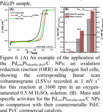
Figure 6. (A) An example of the application of the PdcorePtultrathin-shell/C NPs: an oxidation reduction reaction (ORR) in hydrogen fuel cells, showing the corresponding linear scan voltammograms (LSVs) recorded at 1 mV·s-1 for this reaction at 1600 rpm in an oxygen- saturated 0.5 M H2SO4 solution. (B) Mass and specific activities for the PdcorePtultrathin-shell/C NPs in comparison with their countermetallic Pd/C and Pt/C commercial catalysts.
Fig. 6 shows comparisons with carbon-based counterparts, i.e. the commercial BASF Pd/C and E-tek Pt/C NPs (20 wt. %). The data presented in Fig. 6A have been normalized to the geometric area of the rotating disk electrode (RDE; 0.1964 cm2), where all the electrochemical measurements used the same weight loading of an active metal, i.e. 0.22 mg·cm-2. In particular for PdcorePtultrathin-shell/C NPs, the calculation is based on their active Pt metal-shell. Mass and specific activities at 0.9 VRHE are given as kinetic current density (jk) normalized in reference to the weight loading amount and the electrochemically active surface area (ECSA) of an active metal, respectively.
The intrinsic ORR activities, both mass and specific activities (jk) for the Pd/C, Pt/C, and PdcorePtultrathin-shell/C NPs under similar experimental conditions were calculated based on the LSVs curves (Fig. 6A). In practice the jk
value was calculated from the ORR-LSVs curve by using mass-transport correction and normalized to the weight loading amount and the ECSA of an active metal in order to compare the mass and specific activities of the NPs, respectively (the detailed steps of the calculation are provided in the supporting information). The corresponding results are presented in Fig. 6B.
It can be seen that PdcorePtultrathin-shell/C NPs
11 show an enhanced in both mass and specific
activities compared to Pd/C and Pt/C. To be specific, the PdcorePtultrathin-shell/C NPs exhibited a specific activity of 665 μA·cm-2 at 0.9 V, which is more than double of that for Pt/C (268 μA·cm-2) and almost twenty times than that for the Pd/C (37.5 μA·cm-2). For a mass activity, a similar tendency is observed, where its sequence follows the order: PdcorePtultrathin-shell/C > Pt/C >
Pd/C. In this study, the measured mass and specific activities for this sort of Pt-monolayered nanostructure are in good agreement with the reported values in the literature, e.g. the Adzic et al.’s work.24
The sequence in the mass and specific activities is also consistent with the results from the cyclic voltammograms (Fig. S6), where the Pt-ultrathin layer shifts the onset of metal-oxide formation and oxide reduction (indicated with arrows) to more positive potentials compared to the Pd/C NPs, indicating that a Pt-ultrathin layer inhibits surface chemisorption of oxygenated species at high potentials,25 and could lead to an enhancement in ORR kinetics.49-50 Reducing the Pt content of the cathode electrocatalyst while increasing the activity of Pt-ultrathin layered NPs makes this particular Pt-ultrathin layered nanostructure a very promising solution to one of the major problems of existing fuel cell technology.
CONCLUSION. We have shown that the present kinetically-controlled autocatalytic chemical process can be effectively used as a general protocol for the fabrication of well- defined bimetallic core@shell structured NPs, such as Pd@Pt, Pt@Pd, Ir@Pt, and Ir@Pd, etc.
The presented method, which utilizes the strong reducing ability of the adsorbed hydrogen on the surface of noble metals, can reduce the Cu precursors and subsequently forms only a Cu- ultrathin layer on these metals’ surfaces. This is because the Cu- ultrathin layer is inactive towards hydrogen and so can restrict the self- nucleation of additional thick Cu atom-layers.
This sort of kinetically-controlled synthesis has been clearly described in our first principles DFT calculations, and it elegantly overcomes the drawbacks of the conventional thermodynamically-controlled electrochemical (i.e. UPD) method, namely its limited production capacity. The resulting Cu-ultrathin layer was sacrificially oxidized to form another metal-ultrathin layer shell through the redox
process. The selected core-shell NPs with their multifunctionalities and enhanced properties have been tested in one particularly critical catalytic reaction, this being the oxygen reduction reaction in hydrogen fuel cells.
METHODS.
Materials. Commercial Pd/C (20 wt. %) catalyst purchased from BASF Fuel Cell Inc.
and used as the core material. The Cu and Pt precursor salts, i.e. K2PtCl4 and CuCl2.2H2O were purchased from Alfa Aesar. The ethanol (HPLC grade) was purchased from Sigma Aldrich and used as received.
Synthesis of PdcorePtultrathin-shell/C catalyst.
The synthesis procedure was initiated by sonicating 0.266 g of Pd/C catalyst in 50 mL mixed solvent [ethanol-water (1:1)] for 1 h to form a uniform suspension. This Pd/C suspension was then treated with H2 gas under a constant stirring for 2 h. Later, an aqueous solution of 50 mL of 5×10⁻³ M CuCl2 was added into the reaction flask containing pretreated Pd/C suspension and stirred for 6 h under constant H2 gas purging. The resulting nanoparticles were then isolated from their solvent using a high power centrifugal pump (20,000 rpm for 30 min) and re-dispersed in 50 mL [ethanol-water (1:1)]. Into this suspension, an aqueous solution of 50 mL of 5×10⁻³ M K2PtCl4 was added at a flow rate of 1 mL/min.
The reaction temperature was raised to 60 ºC at a heating rate of 5 ºC/min and maintained for another 6 h under a N2 atmosphere using a standard airless technique. Finally, the resulting product was washed by centrifugation and then dried at 80 ºC in an air oven for about 8 h.
In Situ EC-FTIR Measurements. A conventional three-electrode electrochemical cell with a high surface area Pt counter electrode and a saturated calomel electrode (SCE) reference electrode, powered by a Solartron 1480 Potentiostat/Galvanostat. The working electrode was made of the catalyst slurry with a loading of 37 µg catalyst/cm2 immobilized on polished Au surface (diameter of 1.3 cm) as described in our previous report.28 Prior to the measurements, Ar gas was purged into 0.1 M HClO4 electrolyte solution for 30 min, following which 10 cycles of continuous cyclic voltammograms (potential range of 0.00 – 1.00 VRHE) were subsequently applied to the catalyst. CO adsorption on the catalyst’s
12 surface was carried out by holding the potential
at 0.05 V and simultaneously purging CO gas into this HClO4 solution for 30 min. Next the dissolved CO was removed by purging with N2
gas for 15 min and the corresponding infrared spectrum for the adsorbed CO was recorded afterwards. The FTIR spectra were recorded using the infrared end-station of a Thermo- Fisher-Nicolet Magna 860 Spectrometer equipped with an MCT/A detector at the beam- line BL14A1 of National Synchrotron Radiation Research Center (NSRRC), Hsinchu, Taiwan.
The configuration of the spectro- electrochemical cell for this study was similar to that described in our previous report.28
TEM and in situ XAS Measurements. A FEI-TEM-2000 microscope was used in the TEM measurement and was operated at an accelerating voltage of 3800 kV. Specimens were prepared by ultrasonically suspending the nanoparticles in ethanol, which were then applied to a molybdenum (Mo) grid and dried in air. The XAS spectra were recorded at the Taiwan Beam Line of BL07A1 and at BL01C1 at the NSRRC, Hsinchu, Taiwan. The electron storage ring of the NSRRC was operated at 1.5 GeV. A double Si (111) crystal monochromater was employed for energy selection with a resolution ∆E/E better than 1 × 10⁻⁴ at the Pt L3- (11564 eV), Cu K- (8979 eV), and Pd K- (24350 eV) edges. All the spectra were recorded at room temperature in a transmission mode. Three gas-filled ionization chambers were used in series to measure the intensities of the incident beam (I0), the beam transmitted by the sample (It), the beam subsequently transmitted by the reference foil (Ir). The third ion chamber was used in conjunction with the reference samples, which were a Pt foil, a Cu foil, and a Pd foil for the Pt L3-, Cu K-, and Pd K-edges measurements, respectively. The control of parameters for EXAFS measurements, data collection modes and calculation of errors were all done as per the guidelines set by the International XAFS Society Standards and Criteria Committee.51-52
Computation Methodology. We employed the projector-augmented waves (PAW)53-55 generalized gradient approximation (GGA)56-57 as implemented in the Vienna ab initio simulation package (VASP).58-60 In the plane wave calculation, a cutoff energy of 300 eV was applied for all the slab systems. Each slab
system consists of four layers with four atoms per layer. The surface is constructed as a slab within the three-dimensional periodic boundary conditions and models are separated from their images in the direction perpendicular to the surface by a 14 Å vacuum layer. The bottom one layer was kept fixed to the bulk coordinates;
full atomic relaxations were allowed for the top three layers. For these calculations, a 7 × 7 × 1 k-Point mesh was used in the 3 × 3 super cell.
The atoms in the cell were allowed to relax until the forces on unconstrained atoms are less than 0.05 eV Å-1.
Electrode preparation and electrochemical measurements. Millipore water (18 MΩ), sulfuric acid (Across), were used. All experiments were carried out at an ambient temperature of 30 ± 1 °C. A conventional three- electrode electrochemical cell was used for the electrochemical measurements, with a high surface area Pt counter electrode and a saturated calomel electrode (SCE) reference (all potentials in this paper are quoted vs. the RHE electrode), powered by a Solartron (1480 model) Potentiostat/Galvanostat. The working electrode was made of the carbon supported Pt, Pd, and PdcorePtmonoshell NPs immobilized on glassy carbon electrode (GCE) surface. The procedure for the electrode fabrication involved, first, the preparation of a clear suspension by sonicating a known amount of NPs powder dispersed in 0.5% Nafion; second, placing an aliquot of the suspension (7 μL of 6.2 µgPt∙mL1 of the catalyst) on the GCE disc; third air-drying about 5 minutes at room temperature and then at 80 °C to yield a uniform thin film of the catalyst. 0.5 M sulfuric acid was used as a supporting electrolyte for all the experiments.
After fabrication the electrodes were immersed in N2 saturated 200 mL of 0.5 M sulfuric acid and the potential was scanned from 0.00 to 1.05 VRHE about 10 cycles at a scan rate of 0.05 V∙s-1 for the pretreatment. The cyclic voltammograms experiments were performed at a scan rate of 10 mV∙ s-1 with scan range of 0.00 – 1.05 VRHE. For the ORR experiments, the same electrolyte solution was initially purged with O2 gas for 30 min. After this, the LSVs for the ORR were recorded by sweeping the potential from 0.00 to 1.05 V at 1 mV∙s-1 at a rotation speed of 1600 rpm. Meanwhile the detailed steps of calculation for the ECSA and intrinsic ORR activity, i.e.
13 mass and specific activities, are provided in the
supporting information.
ACKNOWLEDGMENT. The authors gratefully acknowledge financial support from the National Science Council (NSC- 99-2120- M-011-001 and NSC-97-2221-E-011-075- MY3), and facilities from the National Synchrotron Radiation Research Center (NSRRC), the National Taiwan University of Science and Technology (NTUST), and National Center for High Performance Computing (NCHC), Taiwan.
SUPPORTING INFORMATION
AVAILABLE. The results showing the FT- EXAFS spectra of the experimental and two- shell fitting data at various reaction steps during the formation of the PdcorePtultrathin-shell/C NPs (Fig. S1) with their corresponding structural parameters (Table S1), Cu K-edge XANES spectra for the deposition of Cu-ultrathin layer on the surface of various noble metal NPs, e.g.
Pt/C and Ir/C (Fig. S2), CVs in the in situ stripping of the adsorbed Cu-ultrathin layer on Pd/C NPs, as a function of time (Fig S3), DFT modelling of a Cu atom deposition on Pd(111) and Cu(111) slab surfaces (Fig. S4) with their corresponding binding energies (Table S2), HAADF-STEM images of Pdcore-Cuultrathin-shell
cubic shape with its line profile analysis and EDX spectrum (Fig. S5), XANES spectra of the as-prepared spherical-shaped PdcorePtultrathin-shell
/C NPs at the Pd K-, Cu K-, and Pt L3-edges (Fig. S6), cyclic voltammograms for a Pt- ultrathin layer on Pd/C NPs obtained via redox displacement of Cu-ultrathin layer compared with those of monometallic Pd/C and Pt/C counterparts (Fig. S7A), together with their corresponding ECSA values (Fig. S7B), and their stretching properties of the adsorbed CO on Pd (111), Pt (111), and PtmonoshellPdcore (111) slab systems calculated from DFT modelling (Table S3), EDX spectra of the as-prepared and electrochemically treated spherical-shaped PdcorePtultrathin-shell/C NPs together with their corresponding Pd:Pt:Cu atomic composition (Fig. S8), TEM images of the spherical- and cubical-shaped PdcorePtultrathin-shell NPs (Fig. S9), and XRD patterns of the spherical- and cubical- shaped PdcorePtultrathin-shell NPs, are provided. This material is available free of charge via the Internet at: http://pubs.acs.org.
REFERENCES.
1. Greeley, J.; Stephens, I. E. L.; Bondarenko, A. S.; Johansson, T. P.; Hansen, H. A.;
Jaramillo, T. F.; Rossmeisl, J.;
ChorkendorffI; Nørskov, J. K. Alloys of Platinum and Early Transition Metals as Oxygen Reduction Electrocatalysts. Nat.
Chem. 2009, 1, 552-556.
2. Stamenkovic, V. R.; Fowler, B.; Mun, B. S.;
Wang, G.; Ross, P. N.; Lucas, C. A.;
Marković, N. M. Improved Oxygen Reduction Activity on Pt3Ni(111) via Increased Surface Site Availability. Science 2007, 315, 493-497.
3. Alloyeau, D.; Ricolleau, C.; Mottet, C.;
Oikawa, T.; Langlois, C.; Le Bouar, Y.;
Braidy, N.; Loiseau, A. Size and Shape Effects on the Order-Disorder Phase Transition in CoPt Nanoparticles. Nat.
Mater. 2009, 8, 940-946.
4. Sato, K. Magnetic nanoparticles: When Atoms Move Around.Nat. Mater. 2009, 8, 924-925.
5. Cao, A.; Veser, G. Exceptional High- temperature Stability through Distillation- like Self-Stabilization in Bimetallic Nanoparticles. Nat. Mater. 2010, 9, 75-81.
6. Seo, W. S.; Lee, J. H.; Sun, X.; Suzuki, Y.;
Mann, D.; Liu, Z.; Terashima, M.; Yang, P.
C.; McConnell, M. V.; Nishimura, D. G. et al. H. FeCo/Graphitic-Shell Nanocrystals as Advanced Magnetic-Resonance-Imaging and Near-Infrared Agents. Nat. Mater.
2006, 5, 971-976.
7. Reiss, G.; Hutten, A. Magnetic nanoparticles: Applications beyond Data Storage. Nat. Mater. 2005, 4, 725-726.
8. Park, J.-I.; Cheon, J. Synthesis of “Solid Solution” and “Core-Shell” Type Cobalt−Platinum Magnetic Nanoparticles via Transmetalation Reactions. J. Am.
Chem. Soc. 2001, 123, 5743-5746.
9. Lee, W. R.; Kim, M. G.; Choi, J. R.; Park, J.
I.; Ko, S. J.; Oh, S. J.; Cheon, J.
Redox−Transmetalation Process as a Generalized Synthetic Strategy for
14 Core−Shell Magnetic Nanoparticles. J. Am.
Chem. Soc. 2005, 127, 16090-16097.
10. Zhang, S.; Lopez, F. J.; Hyun, J. K.;
Lauhon, L. J. Direct Detection of Hole Gas in Ge−Si Core−Shell Nanowires by Enhanced Raman Scattering. Nano Lett.
2010, 10, 4483-4487.
11. Zhang, J.; Sasaki, K.; Sutter, E.; Adzic, R.
R. Stabilization of Platinum Oxygen- Reduction Electrocatalysts Using Gold Clusters. Science 2007, 315, 220-222.
12. Zhang, J.; Vukmirovic, M. B.; Xu, Y.;
Mavrikakis, M.; Adzic, R. R. Controlling the Catalytic Activity of Platinum- Monolayer Electrocatalysts for Oxygen Reduction with Different Substrates. Angew.
Chem. Int. Ed. 2005, 117, 2170-2173 13. Sasaki, K.; Naohara, H.; Cai, Y.; Choi, Y.
M.; Liu, P.; Vukmirovic, M. B.; Wang, J.
X.; Adzic, R. R. Core-Protected Platinum Monolayer Shell High-Stability Electrocatalysts for Fuel-Cell Cathodes Angew. Chem. Int. Ed. 2010, 49, 8602- 8607.
14. Yam, V. W. W. Behind Platinum's Sparkle.
Nat. Chem. 2010, 2, 790.
15. Schmid, G.; Lehnert, A.; Malm, J.-O.;
Bovin, J.-O. Ligand-Stabilized Bimetallic Colloids Identified by HRTEM and EDX.
Angew. Chem., Int. Ed. Engl. 1991, 30, 874-876.
16. Lim, B.; Lu, X.; Jiang, M.; Camargo, P. H.
C.; Cho, E. C.; Lee, E. P.; Xia, Y.Facile Synthesis of Highly Faceted Multioctahedral Pt Nanocrystals through Controlled Overgrowth. Nano Lett. 2008, 8, 4043-4047.
17. Fang, B.; Chaudhari, N. K.; Kim, M.-S.;
Kim, J. H.; Yu, J.-S. Homogeneous Deposition of Platinum Nanoparticles on Carbon Black for Proton Exchange Membrane Fuel Cell. J. Am. Chem. Soc.
2009, 131, 15330-15338.
18. Peng, Z.; Yang, H. Synthesis and Oxygen Reduction Electrocatalytic Property of Pt-
on-Pd Bimetallic Heteronanostructures. J.
Am. Chem. Soc. 2009, 131, 7542-7543.
19. Lim, B.; Jiang, M.; Camargo, P. H. C.; Cho, E. C.; Tao, J.; Lu, X.; Zhu, Y.; Xia, Y. Pd- Pt Bimetallic Nanodendrites with High Activity for Oxygen Reduction. Science 2009, 324, 1302-1305.
20. Habas, S. E.; Lee, H.; Radmilovic, V.;
Somorjai, G. A.; Yang, P.Shaping Binary Metal Nanocrystals through Epitaxial Seeded Growth. Nat. Mater. 2007, 6, 692- 697.
21. Lee, H.; Habas, S. E.; Somorjai, G. A.;
Yang, P. Localized Pd Overgrowth on Cubic Pt Nanocrystals for Enhanced Electrocatalytic Oxidation of Formic Acid.
J. Am. Chem. Soc. 2008, 130, 5406-5407.
22. Wang, Y.; Toshima, N. Preparation of Pd−Pt Bimetallic Colloids with Controllable Core/Shell Structures. J. Phys. Chem. B 1997, 101, 5301-5306.
23. Toshima, N.; Shiraishi, Y.; Shiotsuki, A.;
Ikenaga, D.; Wang, Y. Novel Synthesis, Structure and Catalysis of Inverted Core/Shell Structured Pd/Pt Bimetallic Nanoclusters. Eur. Phys. J. D. 2001, 16, 209-212.
24. Wang, J. X.; Inada, H.; Wu, L.; Zhu, Y.;
Choi, Y.; Liu, P.; Zhou, W.-P.; Adzic, R. R.
Oxygen Reduction on Well-Defined Core−Shell Nanocatalysts: Particle Size, Facet, and Pt Shell Thickness Effects. J. Am.
Chem. Soc. 2009, 131, 17298.
25. Zhang, J.; Mo, Y.; Vukmirovic, M. B.; Klie, R.; Sasaki, K.; Adzic, R. R. Platinum Monolayer Electrocatalysts for O2
Reduction: Pt Monolayer on Pd(111) and on Carbon-Supported Pd Nanoparticles. J.
Phys. Chem. B 2004, 108, 10955-10964.
26. Sasaki, K.; Wang, J. X.; Naohara, H.;
Marinkovic, N.; More, K.; Inada, H.; Adzic, R. R. Recent Advances in Platinum Monolayer Electrocatalysts for Oxygen Reduction Reaction: Scale-up Synthesis, Structure and Activity of Pt Shells on Pd Cores. Electrochim. Acta 2010, 55, 2645-