國立臺灣大學電機資訊學院電信工程學研究所 博士論文
Graduate Institute of Communication Engineering College of Electrical Engineering and Computer Science
National Taiwan University Doctoral Dissertation
循環脈衝形預編碼用於正交分頻多工之 新波形及收發機最佳化設計
Circularly Pulse-Shaped Precoding for OFDM:
A New Waveform and Its Transceiver Optimization Design
黃彥銘 Yenming Huang
指導教授:蘇柏青博士 Advisor: Borching Su, Ph.D.
西元 2019 年 2 月 February, 2019
摘要
本論文提出了一個循環脈衝形預編碼用於正交分頻多工的新波形,
簡稱「CPS-OFDM」,及其收發機最佳化設計。CPS-OFDM 以針對個別 使用者靈活制定的預編碼器為特色,同時具備低子頻帶外散射(low out-of-subband emission)和低峰均功率比(low peak-to-average power ratio)的優點,這是第五代行動通訊系統(5G)中的各樣場景,如分 散式頻譜存取、新型用戶端設備、高載波頻率通信,皆渴望的兩個主 要的實體層訊號特性。與使用加窗或濾波技巧的大部分現有候選波形 不同,CPS-OFDM 預防了傳送訊號的區塊延展,它會造成額外的區塊 間干擾和波封波動,對訊號接收和功率放大器不利。我們構想了一個 循環脈衝形預編碼器的原型整形向量(prototype shaping vector)最佳化 問題,用來在傳送端可控制子頻帶外散射功率和雜訊增強損害(noise enhancement penalty)的情況下,最小化瞬時功率變異量(variance of instantaneous power)。為了要解決這涉及四階目標函數的最佳化問題,
利用了蓋最小化(majorization-minimization)演算法框架。藉由證明所 提出之問題的凸性質(convexity),不因輸入資料而變的全域最佳解被 保證可經由數次疊代計算後取得。模擬結果呈現了我們所提出的方法,
對於第五代行動通訊系統的實際案例,如非同步傳輸(asynchronous transmissions)、混合系統參數(mixed numerologies),有在接收端檢測 可靠度和整體頻譜效率上的優勢。
此外,在 CPS-OFDM 的基礎之上,許多相關的問題也被研究,以 進一 步 在某 些 實際 的 第 五代 行 動通 訊 系統 場 景 中,提 升 其系 統 效 能。對於一個需要相當高功率放大器效能的低成本機器,一個星座
圖整形(constellation shaping)最佳化的方法被提出,可有效地降低
CPS-OFDM 訊號的立方度量(cubic metric)。為了方便採取不同系統參
數的第四代和第五代行動通訊系統在同一個頻帶上共存,或更廣義地 說,異質頻譜存取,提出了採用 CPS-OFDM 傳輸,以重新利用保護頻 帶和同時用作頻譜整形的想法。
根據本論文所展示的分析推導、最佳化問題構想、及模擬結果,我 們強烈地相信,所提出的 CPS-OFDM 與其收發機架構,將會成為第五 代行動通訊系統及未來最有前途的技術之一。
關鍵字: 第五代行動通訊系統,新無線電,新波形,正交分頻多工,
離散傅利葉轉換散布正交分頻多工,循環脈衝形預編碼器,低子頻帶 外散射,低峰均功率比,瞬時功率變異量,蓋最小化,立方度量,星 座圖整形,凸最佳化,收發機設計,異質頻譜存取,植入式廣義分頻 多工,頻譜整形
Abstract
A new circularly pulse-shaped (CPS) precoding orthogonal frequency di- vision multiplexing (OFDM) waveform, or CPS-OFDM for short, and the transceiver optimization design, are proposed in this dissertation. CPS-OFDM characterized by user-specific precoder flexibility possesses the advantages of both low out-of-subband emission (OSBE) and low peak-to-average power ra- tio (PAPR), which are two major desired physical-layer signal properties for various scenarios in 5G New Radio (NR), including fragmented spectrum ac- cess, new types of user equipments (UEs), and communications at high carrier frequencies. As opposed to most of the existing waveform candidates using windowing or filtering techniques, CPS-OFDM prevents block extension that causes extra inter-block interference (IBI) and envelope fluctuation unfriendly to signal reception and power amplifier (PA) efficiency, respectively. An opti- mization problem of the prototype shaping vector built in the CPS precoder is formulated to minimize the variance of instantaneous power (VIP) with con- trollable OSBE power (OSBEP) and noise enhancement penalty (NEP). In or- der to solve the optimization problem involving a quartic objective function, the majorization-minimization (MM) algorithmic framework is exploited. By proving the convexity of the proposed problem, the globally optimal solution invariant of incoming data is guaranteed to be attained via numbers of iter- ations. Simulation results reveal the advantages of the proposed scheme in terms of detection reliability and spectral efficiency for practical 5G cases such as asynchronous transmissions and mixed numerologies.
In addition, on a foundation of CPS-OFDM, several relevant problems are also studied to further improve the system performance in certain practical 5G NR scenarios. For a low-cost machine demanding a rather high PA efficiency at the transmitter, a constellation shaping optimization method is proposed to effectively reduce the cubic metric (CM) of CPS-OFDM signals. To facilitate the coexistence of 4G and 5G with different numerologies in the same band, or more generally, heterogeneous spectrum access, the idea of adopting CPS- OFDM transmission to reuse the guard bands and at the same time serve as spectrum shaping is introduced.
According to the analytical derivations, the optimization problem for- mulations, and the simulation results demonstrated in this dissertation, we strongly believe that the proposed CPS-OFDM along with its transceiver ar- chitecture will be one of the most promising technologies in 5G and beyond.
Keywords: 5G, New Radio (NR), new waveform, OFDM, DFT-S-OFDM, circularly pulse-shaped (CPS) precoding, low out-of-subband emission (OSBE), low peak-to-average power ratio (PAPR), variance of instantaneous power (VIP), majorization-minimization (MM), cubic metric (CM), constellation shaping, convex optimization, transceiver design, heterogeneous spectrum access, embedded-GFDM, spectrum shaping
Contents
摘要 v
Abstract vii
1 Introduction 1
1.1 5G Physical-Layer Signal Requirements . . . 2
1.2 State-of-the-Art of 5G New Waveform Development . . . 4
1.2.1 WOLA-OFDM . . . 4
1.2.2 UF-OFDM and f-OFDM . . . 5
1.2.3 DFT-S-OFDM and Its Variants . . . 5
1.2.4 GFDM . . . 5
1.2.5 Precoded-OFDM . . . 6
1.3 Main Contributions of the Dissertation . . . 6
1.4 Organization of the Dissertation . . . 7
1.5 Notations . . . 9
1.6 Acronyms . . . 10
2 Circularly Pulse-Shaped Precoding for OFDM and Its Optimal Prototype Shaping Vector Design 11 2.1 System Model and Problem Statement . . . 12
2.1.1 Quantifying Spectral Sidelobe Leakage Using OSBEP . . . 15
2.1.2 Quantifying Envelope Fluctuation Using VIP . . . 16
2.1.3 Subband Precoder Design Problem . . . 16
2.2 Circularly Pulse-Shaped Precoding for OFDM . . . 17
2.2.1 CPS Precoder Implementation and Complexity Analysis . . . 18
2.2.2 OSBEP of CPS-OFDM Transmission . . . 23
2.2.3 VIP of CPS-OFDM Signals . . . 24
2.2.4 NEP for CPS-OFDM Signal Reception . . . 24
2.2.5 CPS-OFDM as a Generalized DFT-S-OFDM . . . 25
2.3 Optimization of the Prototype Shaping Vector . . . 25
2.3.1 Solving the Problem by Majorization-Minimization (MM) . . . . 27
2.3.2 Choices of OSBEP Upper Bound and Initial Point in (2.44) . . . . 29
2.4 Performance Evaluations of 5G OFDM-Based Waveform Candidates . . . 30
2.4.1 Simulation Parameters, Assumptions, and Cases . . . 30
2.4.2 Settings of Existing Waveforms for Comparisons . . . 32
2.4.3 Settings of the Proposed CPS-OFDM Waveform . . . 34
2.4.4 Case 1b: Interference-Free Single User Performance . . . 35
2.4.5 Case 3: Asynchronous Multiuser Uplink Performance . . . 37
2.4.6 Case 4: Mixed Numerology Multiuser Uplink Performance . . . . 37
2.4.7 Spectral Efficiency Analysis . . . 38
2.4.8 Summary of Simulation Results . . . 39
2.5 Concluding Remarks . . . 50
2.6 Appendix . . . 51
2.6.1 Derivations of PSD and OSBEP for CPS-OFDM . . . 51
2.6.2 Convexity and Matrix Quadratic Form of f (X) . . . . 52
2.6.3 Introduction to Majorization-Minimization (MM) Algorithm . . . 53
2.6.4 Comparisons of Using Different Prototype Shaping Vectors . . . 56
2.6.5 Other 5G OFDM-Based System Models . . . 59
3 Reducing Cubic Metric of Circularly Pulse-Shaped OFDM Signals Through Constellation Shaping Optimization With Performance Constraints 63 3.1 Introduction of This Work . . . 63
3.2 CPS-OFDM System Model and Problem Statement . . . 65
3.2.1 Cubic Metric (CM) . . . 67
3.2.2 Block-wise Error Vector Magnitude (EVM) . . . 68
3.2.3 Out-of-Subband Emission Energy (OSBEE) . . . 68
3.2.4 Offset Vector Design Problem . . . 69
3.3 Constellation Shaping Optimization Method . . . 69
3.4 Simulation Results . . . 71
3.4.1 Simulation Parameters and Assumptions . . . 71
3.4.2 Performance Evaluations . . . 72
3.5 Concluding Remarks . . . 77
3.6 Appendix: Derivation of OSBEE in Quadratic Form . . . 77
4 Heterogeneous LTE Downlink Spectrum Access Using CPS-OFDM 79 4.1 Introduction of This Work . . . 80
4.2 OFDMA System Model and Problem Formulation . . . 82
4.2.1 Precoder Design Problem for Spectrum Shaping . . . 85
4.3 Spectrum Shaping by CPS-OFDM . . . 86
4.4 Simulation Results . . . 88
4.4.1 Simulation Setup . . . 89
4.4.2 Performance Evaluations . . . 89
4.5 Concluding Remarks . . . 94
5 Conclusions and Future Work 95
Bibliography 97
List of Figures
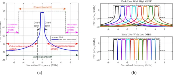
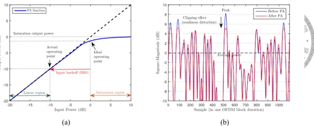
1.1 Illustration of OSBE: (a) the spectral leakage, outside the guard band, of a user assigned to a portion of contiguous OFDM subcarriers (b) more users multiplexing in a channel bandwidth if each of them has low OSBE. . . . 2 1.2 Illustrations of (a) a PA operation model (b) PA nonlinear distortion im-
posed on transmitted baseband signals. . . 3 1.3 Illustrations of (a) spectral regrowth effect (b) mixing products between
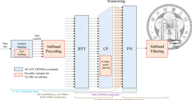
the individual frequency components due to PA nonlinearity. . . 3 1.4 Transmitter structure of OFDM-based waveform for 5G NR. . . 4
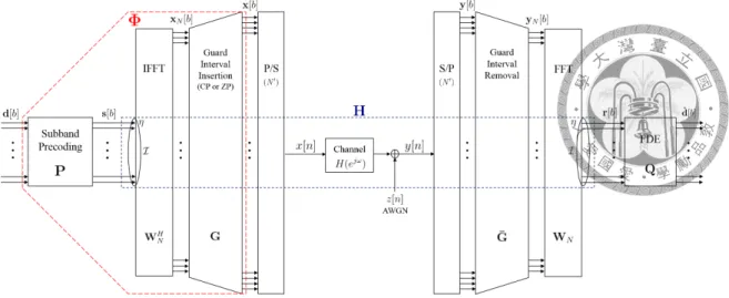
2.1 Subband-wise precoded-OFDM baseband transceiver system model. . . . 13 2.2 Proposed CPS-OFDM baseband transmitter model. . . 18 2.3 Three time-frequency structure illustrations in which CPS-OFDM can be
viewed as a generalized form of OFDMA and SC-FDMA. . . 19 2.4 Propsoed CPS precoder with (a) direct implementation (2.29a), (b) frequency-
domain implementation (2.29b), and (c) characteristic-matrix-domain im- plementation (2.29c). . . 22 2.5 A generalized simulation flowchart of different waveform generation at
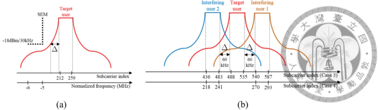
the transmitter. . . 31 2.6 Illustrations of the settings of the required guard band size ∆ for (a) Case
1b, (b) Case 3 and Case 4. . . 32 2.7 Illustrations of the optimized prototype shaping vectors obtained by Al-
gorithm 1 with respect to different parameter settings of CPS-OFDM in Case 1b. . . 40
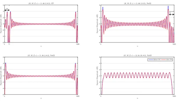
2.8 Visualization of the optimized CPS-OFDM waveforms for the setting of
|K| ≥ 2 with different GI types. . . 41 2.9 Visualization of the optimized CPS-OFDM waveforms for the setting of
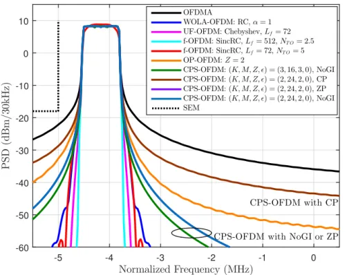
|K| = 1 with different GI types. . . 41 2.10 Simulated PSD results of the waveforms claiming low OSBE in the ab-
sence of PA, where WOLA-OFDM, UF-OFDM, and f-OFDM ideally have extremely low OSBE at the cost of increased PAPR and induced IBI. . . . 42 2.11 PAPR performance results of the waveforms claiming low OSBE, where
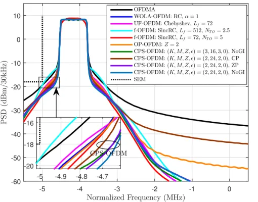
CPS-OFDM yields much lower PAPR and so ensures better PA efficiency as compared to the others. . . 42 2.12 Simulated PSD results of the waveforms claiming low OSBE in the pres-
ence of PA with the IBO of 3 dB, where CPS-OFDM in practice leads to the lowest amount of OSBE in adjacent bands because of its low PAPR. . 43 2.13 Single user detection performance results in terms of uncoded 16-QAM,
IBO of 3 dB, and TDL-C-300 channel, where CPS-OFDM with CP pos- sesses the best signal reliability at the receiver. . . 43 2.14 Simulated PSD results of the waveforms claiming low PAPR in the ab-
sence of PA, where SC-FDMA and SS-SC-FDMA do not address OSBE issues and the controllable passband fluctuation of CPS-OFDM can be seen. 44 2.15 PAPR performance results of the waveforms claiming low PAPR, where
CPS-OFDM can further reduce the PAPR by allowing some NEP (ϵ > 0) for the optimal prototype shaping vector design. . . 44 2.16 Simulated PSD results of the waveforms claiming low PAPR in the pres-
ence of PA with the IBO of 3 dB, where CPS-OFDM benefited from the design flexibility can handle the issues of OSBE, PAPR, and NEP adaptively. 45 2.17 Single user detection performance results in terms of uncoded 16-QAM,
IBO of 3 dB, and TDL-C-300 channel, where CPS-OFDM with|K| < K can further improve the BER thanks to the frequency diversity. . . 45
2.18 Target user BER performance comparison of the waveforms claiming low OSBE in the asynchronous multiuser uplink case with IBO of 3 dB, where CPS-OFDM with CP is much more robust to the relative TOs than the others. 46 2.19 Target user BER performance comparison of the waveforms claiming low
PAPR in the asynchronous multiuser uplink case with IBO of 3 dB, where CPS-OFDM can outperform the others by selecting proper parameters. . . 46 2.20 Target user BER performance comparison of the waveforms claiming low
OSBE in the mixed numerology multiuser uplink case with IBO of 3 dB, where the superiority of CPS-OFDM over the others can be found. . . 47 2.21 Target user BER performance comparison of the waveforms claiming low
PAPR in the mixed numerology multiuser uplink case with IBO of 3 dB, where CPS-OFDM offers better detection reliability compared to the others. 47 2.22 Spectral efficiency comparisons of the waveforms claiming low OSBE in
the interference-free single user case, the asynchronous multiuser case, and the mixed numerology multiuser case at Eb/N0 = 25 dB. . . 48 2.23 Spectral efficiency comparisons of the waveforms claiming low PAPR in
the interference-free single user case, the asynchronous multiuser case, and the mixed numerology multiuser case at Eb/N0 = 25 dB. . . 48 2.24 Illustration of the MM procedure. . . 54 2.25 Simulated PSD results of CPS-OFDM waveforms using different proto-
type shaping vectors in the absence of PA, where the traditional use of the RRC vector leads to the worst OSBE performance. . . 57 2.26 PAPR performance results of CPS-OFDM waveforms using different pro-
totype shaping vectors, where the PAPR can be reduced mainly by allow- ing NEP (ϵ > 0). . . . 57 2.27 Simulated PSD results of CPS-OFDM waveforms using different proto-
type shaping vectors in the presence of PA with the IBO of 3 dB. . . 58
2.28 Single user detection performance results in terms of uncoded 16-QAM, IBO of 3 dB, and TDL-C-300 channel, where using the optimized proto- type shaping vectors have much better detection reliability than using the
RRC vector with large NEP. . . 58
2.29 OFDM baseband transceiver system model. . . 60
2.30 WOLA-OFDM baseband transceiver system model. . . 60
2.31 UF-OFDM baseband transceiver system model. . . 60
2.32 f-OFDM baseband transceiver system model. . . 61
2.33 DFT-S-OFDM (a.k.a. SC-FDMA) baseband transceiver system model. . . 61
2.34 SS-SC-FDMA baseband transceiver system model. . . 61
2.35 ZT DFT-S-OFDM baseband transceiver system model. . . 62
2.36 CPS-OFDM baseband transceiver system model with NoGI. . . 62
3.1 CPS-OFDM baseband transceiver system model with constellation shaping. 66 3.2 Scatterplots of the optimized offset data symbols in terms of different EVMmaxvalues for OFDM and CPS-OFDM. . . 73
3.3 The proposed optimal offset data vector design (3.20) can further reduce the RCM of CPS-OFDM signals to meet the requirement of high PA effi- ciency. . . 75
3.4 Simulated PSD results (IBO = 0 dB) that the spectral containment of CPS-OFDM can be further improved by the proposed scheme (3.20). . . . 75
3.5 Uncoded 16-QAM BER results that the utilization of constellation shaping is accompanied with slight detection performance degradation. . . 76
3.6 Spectral efficiency improvement through the proposed constellation shap- ing technique mainly due to the decrease of the required guard bands. . . 76
4.1 Illustration of the proposed spectrum shaping idea for a 4G LTE downlink band sharing with a 5G RAT using different numerology. . . 81
4.2 An OFDMA-based transceiver architecture in which the precoder P is to be designed for spectrum shaping. . . 82
4.3 A profile of the proposed fragmented spectrum assignment in a licensed LTE downlink band. . . 85 4.4 Time-frequency structure of adopting CPS-OFDM, namely, embedded-
GFDM, when the RB is used for the 5GRAT. . . 86 4.5 Tight spectral containment achieved by CPS-OFDM with Kg = 1 and
Mg= 2 for the downlink transmission in the BB. . . 90 4.6 CPS-OFDM functioning as the spectrum shaping of legacy OFDMA trans-
mission gaining much more spectrum efficiency compared to GB utilization. 92 4.7 Illustration of the flexibility of CPS-OFDM that the level of spectrum
shaping depends on the frequency range of the BB . . . 92 4.8 No additional PA burden for the legacy BS when introducing the proposed
CPS-OFDM to the BB. . . 93 4.9 No detection performance degradation for the legacy UE due to orthogo-
nality preservation with the advanced UE and only 2 dB BER gap for the advanced UE due to the additional precoder P being non-unitary causing NEP. . . 93
List of Tables
1.1 List of abbreviations. . . 10 2.1 Summary of representative simulation results for Case 1b, Case 3, and
Case 4 with four different transmission types. . . 49 4.1 OFDMA system parameters. . . 89 4.2 CPS-OFDM parameters for the BB communication. . . 89
Chapter 1 Introduction
The Third Generation Partnership Project (3GPP) has initiated the standardization activity for the fifth generation (5G), officially named as New Radio (NR), since 2016. The new air-interface has been envisioned to support diverse use cases, broadly classified as en- hanced mobile broadband (eMBB), ultra-reliable low-latency communications (URLLC), and massive machine type communications (mMTC), operated in a wide range of frequen- cies and deployment scenarios [1]. Waveforms of NR, on basis of orthogonal frequency division multiplexing (OFDM) [2], are being developed to flexibly address various emerg- ing applications and physical layer signal requirements by providing different transmission properties. Support of discrete Fourier transform spread OFDM (DFT-S-OFDM) based waveforms is mandatory for user equipments (UEs) in view of link budget [2].
OFDM has achieved great success in Long Term Evolution (LTE) of the fourth gen- eration (4G) due to its several merits such as robustness to channel frequency selectivity, plain channel estimation, flexibility in frequency-domain multiple access, easy integra- tion with multiple-input multiple-output (MIMO) technologies, etc [3]. However, differ- ent from 4G LTE, there are new application scenarios such as fragmented spectrum usage including asynchronous transmissions and mixed numerologies, low-cost machines, and communications at high carrier frequencies in upcoming 5G wireless systems [4–6]. Two additional demands, namely, tight spectral containment and resistance to power amplifier (PA) nonlinearity, emerge to fit these new scenarios [7, 8].
1.1 5G Physical-Layer Signal Requirements
The first demand is to lower the out-of-subband emission (OSBE) of a user assigned to a portion of contiguous OFDM subcarriers in a carrier. Figure 1.1(a) illustrates the OSBE, which is different from out-of-band emission that merely concerns the spectral leakage outside the channel bandwidth. For a user with low OSBE, the incurring sidelobe leakage interference imposed on frequency-domain adjacent users in the carrier, for lack of orthog- onality, can be mitigated [9]. More user may be multiplexed together as depicted in Fig.
1.1(b). The virtue of low OSBE makes relaxing stringent synchronization requirements as specified in 4G LTE possible, so as to facilitate grant-free mechanisms potentially aris- ing from URLLC and mMTC. Also, accommodating several services in terms of different subcarrier spacing with diminished guard bands in the channel bandwidth becomes viable.
Normalized Frequency (MHz)
-6 -4 -2 0 2 4 6
PSD(dBm/30kHz)
-50 -40 -30 -20 -10 0 10 20
Mask One user transmission
Out-of-subband emission (OSBE)
Out-of-subband emission (OSBE)
Sampling bandwidth Out-of-band
emission (OOBE)
Out-of-band emission (OOBE) Channel bandwidth
Guard band
Guard band
(a)
-6 -4 -2 0 2 4 6
PSD(dBm/30kHz)
-40 -20 0
Each User With High OSBE
Normalized Frequency (MHz)
-6 -4 -2 0 2 4 6
PSD(dBm/30kHz)
-40 -20 0
Each User With Low OSBE
(b)
Figure 1.1: Illustration of OSBE: (a) the spectral leakage, outside the guard band, of a user assigned to a portion of contiguous OFDM subcarriers (b) more users multiplexing in a channel bandwidth if each of them has low OSBE.
The second demand is to lower the peak-to-average power ratio (PAPR) of baseband signals, where PAPR is the ratio of the peak power to the average power during an inter- val to quantify the signal envelope fluctuation. By doing so, the input backoff (IBO) to maintain the operation in PA linear region can be decreased in order to substantially im- prove the power efficiency, the battery life, and the coverage range of a UE. It also brings down the cost of hardware implementation, particularly for uplink and sidelink devices supporting very high carrier frequencies. Figure 1.2(a) and (b) illustrate a PA operation model and PA nonlinear distortion imposed on transmitted baseband signals, respectively.
Input Power (dB)
-20 -15 -10 -5 0 5 10
OutputPower(dB)
-20 -15 -10 -5 0 5 10
PA function
Saturation output power
Linear region
Input backoff (IBO)
Saturation region Actual
operating point
Ideal operating point
(a)
Sample (in one OFDM block duration) 0 100 200 300 400 500 600 700 800 900 1000
Square-Magnitude(dB)
-10 -8 -6 -4 -2 0 2 4 6 8 10
Before PA After PA Clipping effect
(nonlinear distortion) Peak
Average power
(b)
Figure 1.2: Illustrations of (a) a PA operation model (b) PA nonlinear distortion imposed on transmitted baseband signals.
A joint consideration of lowering OSBE and PAPR together is essential, since unde- sirable PA nonlinearity actually causes spectral regrowth that may deteriorate expected spectral compactness virtue as revealed in Fig. 1.3(a). In more detail, PA nonlinearity imposing on the transmitted signal makes that mixing products between the individual frequency components occur [10] as depicted in Fig. 1.3(b).
Normalized Frequency (MHz)
-5.5 -5 -4.5 -4 -3.5 -3 -2.5 -2 -1.5 -1 -0.5 0
PSD(dBm/30kHz)
-60 -50 -40 -30 -20 -10 0
10 Mask
After PA, IBO = 3 dB After PA, IBO = 8 dB Before PA
Spectral regrowth
Spectral regrowth
(a) (b)
Figure 1.3: Illustrations of (a) spectral regrowth effect (b) mixing products between the individual frequency components due to PA nonlinearity.
Pure OFDM waveform and its orthogonal frequency division multiple access (OFDMA) usage, known to possess severe OSBE and rather high PAPR, need to be improved [4–8].
It is also desirable that newly developed OFDM-based transmission schemes are capable of flexibility in parameter adaptation with backward and forward compatibility [11].
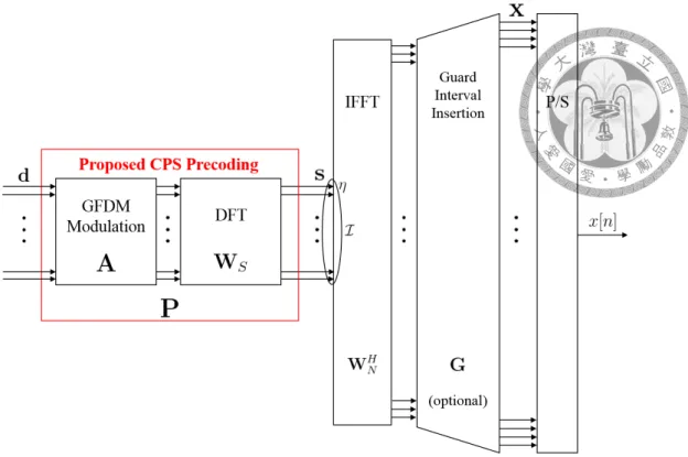
Figure 1.4: Transmitter structure of OFDM-based waveform for 5G NR.
1.2 State-of-the-Art of 5G New Waveform Development
To deal with the two challenging yet crucial issues, auxiliary techniques such as window- ing, filtering, and precoding have been proposed and studied for years [12,13]. Many new waveform candidates arose since then [14, 15]. Most of waveforms studied by 3GPP for 5G NR can be described as a special case depicted in Fig. 1.4, which illustrates a typi- cal transmitter block diagram for OFDM-based waveforms [7]. The inverse fast Fourier transform (IFFT) operation followed by cyclic prefix (CP) is the basic building block in a classical CP-OFDM transmitter. Based on this foundation, additional windowing, sub- band filtering, subband precoding along with zero padding (ZP) in part of data symbols, or alternative type of guard interval (GI) such as ZP and internal GI are considered for further enhancements in various criteria.
1.2.1 WOLA-OFDM
Weighted overlap-and-add (WOLA) OFDM [15–17], as a straightforward windowing ap- proach merely for OSBE suppression, prevents abrupt changes between two rectangularly pulsed OFDM blocks. A widely-known actualization is to multiply the time-domain sam- ples resided in the extended block edges by raised-cosine coefficients (see Fig. 1.4). This
technique generally causes little PAPR overhead and inter-block interference (IBI), which will degrade the reliability of signal reception.
1.2.2 UF-OFDM and f-OFDM
Universal-filtered OFDM (UF-OFDM) [18, 19] and filtered-OFDM (f-OFDM) [20, 21]
introduce the functionality of subband-wise filtering, which ideally results in extremely low OSBE but in practice causes increased PAPR with significant spectral regrowth [22].
The aforementioned two waveforms even give rise to IBI at the receiver, if the GI such as CP and zero padding (ZP) cannot accommodate the composite delay spread of wireless channel and block extension. The finite impulse response (FIR) filter optimization of UF-OFDM and f-OFDM with different filter design philosophies can be found in [23, 24]
1.2.3 DFT-S-OFDM and Its Variants
In contrary to the filter utilization, precoding techniques are usually helpful to PAPR reduction without imposing GI burden. One representative waveform is DFT-S-OFDM that has been adopted in 4G LTE uplink specification, in the name of single-carrier fre- quency division multiple access (SC-FDMA) [25]. Spectrally shaped SC-FDMA (SS- SC-FDMA) [26] is able to achieve a lower PAPR than that of DFT-S-OFDM at the cost of excess bandwidth and noise enhancement penalty (NEP) [27]. The optimization of the spectrally shaping coefficients to statistically reduce the PAPR has been studied in [28,29].
Moreover, DFT-S-OFDM based waveforms can easily yield low OSBE when few input data symbols and CP are replaced by zeros. A famous example is zero-tail (ZT) DFT-S- OFDM [30], although it leads to a slightly higher PAPR than that of DFT-S-OFDM. There are also some studies to change the input zero symbols into specific coefficients for further enhancement [31, 32].
1.2.4 GFDM
Generalized frequency division multiplexing (GFDM) [33], known for its circular pulse shaping [34], can be viewed as a kind of precoded OFDM that flexibly constructs K spec-
trally shaped M -point DFT precoders in front of OFDM modulator implemented with KM -point inverse fast Fourier transform (IFFT) [35]. GFDM is capable of offering lower out-of-band emission and PAPR than those of OFDM [36]. Nevertheless, GFDM has dif- ficulty in multiple access support, since its spectral shaping after each M -point DFT is basically performed on the whole KM subcarriers, unless otherwise specified (e.g., raised cosine shaping with at most 2M coefficients and some null subcarriers are used [37, 38]).
A complex equalization corresponding to the whole KM subcarriers is generally required by the GFDM receiver. GFDM has been proposed to be embedded in OFDM within a sub- band, together with incumbent 4G transmissions, to facilitate future heterogeneous access in legacy spectra [39].
1.2.5 Precoded-OFDM
Apart from DFT-based precoding techniques, other precoder types found in the literature (e.g., [40–43]) often have undesirable complexity and compatibility issues for 5G NR actualization. In particular, the precoders given by [40–43] are only used for out-of-band emission reduction without handling PAPR issues. Among the aforementioned waveform candidates, an optimal subband-wise waveform design to jointly reduce the OSBE and the PAPR with controllable NEP is absent.
1.3 Main Contributions of the Dissertation
In this dissertation, we propose a new circularly pulse-shaped (CPS) precoding OFDM waveform called CPS-OFDM and is transceiver optimization design for 5G NR and be- yond. CPS-OFDM features a generalized low-complexity DFT-based subband precoder structure, which possesses degrees of freedom (DoF) jointly reducing the OSBE and the PAPR with controllable NEP. The proposed CPS precoder can be regarded as a frequency- domain representation of GFDM modulation corresponding to a certain set of contiguous OFDM subcarriers. Similar to the implementation of GFDM modulation [35, 44], the DoF built in the CPS precoder can be treated as either a prototype vector or a charac-
teristic matrix producing all entries of the CPS precoding matrix. To optimize the CPS precoder invariant of incoming data, we consider the statistical quantities of OSBE and PAPR derived from the power spectral density (PSD) and the variance of instantaneous power (VIP), respectively. A quartic minimization problem with complex variables is accordingly formulated to find the optimal prototype vector. As the original problem is difficult to solve, we propose to convert it into a series of simple semidefinite program- ming (SDP) relaxation problems under the majorization-minimization (MM) algorithmic framework [45]. With our proof of the original objective function in matrix quadratic form being convex, the globally optimal solution of the original problem is guaranteed to be attained via MM iteration process [46]. In addition, we introduce a method of choos- ing the initial point, which must be in the feasible set of the first SDP relaxation problem.
These achievements in CPS-OFDM can serve as a universal optimization framework for SS-SC-FDMA [27–29] and GFDM [33].
It is worthy to note that lowering both OSBE and PAPR by such linear precoding also prevents imposing distortion on the transmitted signal, additional power consumption and real-time computation at the transmitter, and side information required by the receiver, as compared to other techniques such as clipping, cancellation carrier, constrained constel- lation shaping, and selective mapping enumerated in [12, 13]. Different from GFDM [33]
and precoded GFDM [47], the proposed CPS-OFDM is a particular form of precoded OFDMA. On the foundation of an OFDMA system, the CPS-OFDM receiver can orthog- onally perform subband-wise equalization for each user in the system friendly to multiuser uplink usage.
1.4 Organization of the Dissertation
This dissertation is organized as follows. In Chapter 2, the proposed CPS-OFDM will be completely introduced by displaying its key ideas, system implementation, optimiza- tion design, and performance evaluations. Particularly, in Section 2.1, a subband-wise precoded-OFDM baseband transceiver system model is first presented in detail. Then, the performance metrics to quantify the spectral sidelobe leakage and the envelope fluctuation
are specified. Lastly, the subband precoder design problem of our interest is qualitatively described. In Section 2.2, a new multicarrier waveform called CPS-OFDM is proposed for 5G NR and beyond. Three equivalent CPS precoder implementation methods are provided along with their complexity analysis. The closed-form expressions of the OSBE power (OSBEP), the VIP, and the NEP of CPS-OFDM are analytically derived. Hence, an opti- mal prototype shaping vector design problem can be mathematically formulated in Section 2.3. The MM procedure of solving the proposed optimization problem is then revealed and summarized as algorithmic pseudo codes. The proposed algorithmic framework en- ables the realization of CPS-OFDM adaptively satisfying the physical-layer requirements of low OSBE and low PAPR in a variety of use cases. In Section 2.4, simulation results exhibit the performance gains of applying the proposed CPS-OFDM to 5G NR in terms of OSBEP, PAPR, bit error rate (BER), and spectral efficiency (SE), as compared to the other waveform candidates including OFDMA, WOLA-OFDM, UF-OFDM, f-OFDM, SC-FDMA, ZT DFT-S-OFDM, and SS-SC-FDMA.
In Chapter 3, a constellation shaping optimization method is proposed to further reduce the cubic metric (CM) of CPS-OFDM signals for the case that demands rather high PA efficiency at the transmitter (e.g., a smart factory with intercommunicating machinery).
Benefited from the extremely low CM, the spectral regrowth is mitigated at the same time so that the overall SE can be improved by diminishing the required guard band size.
In Chapter 4, the idea of spectrum shaping using CPS-OFDM is proposed to facilitate heterogeneous LTE downlink spectrum access. The proposed scheme enables smooth mi- gration from 4G to 5G in the viewpoints of spectrum engineering and commercial cellular operators. The reason is that many upcoming 5G applications may still require backhaul signaling provided by widely-deployed LTE infrastructure and physical characterizations of the bands below 6 GHz for wide coverage and mobility support.
Finally, Chapter 5 summarizes the contributions of this dissertation and makes recom- mendations for future work.
Most of the contents of Chapters 1 and 2 have been published in IEEE Communica- tions Magazine in 2017 [7], IEEE Access (Special Section on New Waveform Design and
Air-Interface for Future Heterogeneous Network towards 5G) in 2018 [48], and the 3GPP technical documents in the early phase of 5G NR standardization in 2016 [49–55]. The material in Chapter 3 has been presented in the proceeding of IEEE Vehicular Technology Conference (VTC) in 2018 [56]. The work in Chapter 4 has been presented in the proceed- ing of IEEE International Conference on Communications (ICC) Workshop on 5G RAN Design in 2016 [39] and published in the 3GPP technical document [57].
1.5 Notations
Boldfaced lower case letters such as x represent column vectors, boldfaced upper case letters such as X represent matrices, and italic letters such as X represent scalars. Super- scripts as in XT, XH, X−1, and X◦−1denote the transpose, transpose-conjugate, inverse, and Hadamard inverse operators, respectively. Calligraphic upper case letters such asI represent sets of discrete indices or continuous intervals. The cardinality of the discrete set I is described as |I|. The submatrix of X formed by the column vectors with the ordered indices given inI is denoted by [X]I. Similarly, the subvector of x is denoted as [x]I. Let 0N×M, 1M, IN, and diag (x) be the N × M zero matrix, the M × 1 vector of ones, the N× N identity matrix, and the diagonal matrix containing x on its diagonal, respectively.
The (N×M)-dimensional complex matrix space is expressed as CN×M. Functions tr (X), vec (X), rank (X), and λmax(X) are the trace, the column-wise vectorization, the rank, and the largest eigenvalue of X, respectively. OperatorsE{·}, ℜ{·}, |·|, ∥·∥2,∥·∥6,∥·∥∞,⟨·⟩S, and⊗ denote expectation, real part of a complex number, modulus of a complex scalar, Euclidean norm, 6-norm, infinity norm, modulo S, and Kronecker product, respectively.
The Kronecker delta is δk,k′ = 1 for k = k′, and δk,k′ = 0 otherwise. The expression X⪰ (≻)Y means that X−Y is a positive semidefinite (definite) matrix. The decibel (dB) representation of a real number C is shown as C|dB.
Throughout the dissertation we adopt zero-based indexing. The N -point normalized DFT matrix denoted by WN is defined as that the (k, n)th entry of WN is e−j2πkn/N/√
N . The ith entry of x and the (i, j)th entry of X are denoted by [x]i and [X]i,j, respectively.
Given any positive integer N ,ZN stands for the set{0, 1, · · · , N − 1}. For any positive
integers K and M , the M×K matrix denoted by reshape (x, M, K) has the (m, k)th entry being [x]kM +m,∀m ∈ ZM, k∈ ZK. The root mean square value of [x]nfor all n∈ ZN is represented by rms([x]n) =
√
1 N ∥x∥22.
1.6 Acronyms
The commonly used abbreviations in the dissertation are listed in Table 1.1 for readability.
3GPP The Third Generation Partnership Project 4G The Fourth Generation Wireless Systems 5G The Fifth Generation Wireless Systems
BER Bit error rate
CI Convex iteration
CP Cyclic prefix
CPS-OFDM Circularly pulse-shaped OFDM
DFT-S-OFDM Discrete Fourier transform spread OFDM
f-OFDM Filtered OFDM
GFDM Generalized frequency division multiplexing
GI Guard interval
IBI Inter-block interference
IBO Input backoff
LTE Long Term Evolution
MM Majorization-minimization
MMSE Minimum mean square error
NEP Noise enhancement penalty
NoGI Without GI
NR New Radio
OFDM Orthogonal frequency division multiplexing OFDMA Orthogonal frequency division multiple access
OSBE Out-of-subband emission
OSBEP OSBE power
PA Power amplifier
PAPR Peak-to-average power ratio
PSD Power spectral density
SC-FDMA Single-carrier frequency division multiple access SS-SC-FDMA Spectrally shaped SC-FDMA
SE Spectral efficiency
UF-OFDM Universal-filtered OFDM VIP Variance of instantaneous power WOLA-OFDM Weighted overlap-and-add OFDM
ZP Zero padding
ZT DFT-S-OFDM Zero-tail DFT-S-OFDM Table 1.1: List of abbreviations.
Chapter 2
Circularly Pulse-Shaped Precoding for OFDM and Its Optimal Prototype
Shaping Vector Design
A new waveform called circularly pulse-shaped OFDM (CPS-OFDM), along with its op- timal prototype shaping vector design, is fully introduced in this chapter. CPS-OFDM, characterized by user-specific DFT-based precoder flexibility, possesses the advantages of both low out-of-subband emission (OSBE) and low peak-to-average power ratio (PAPR).
CPS-OFDM prevents block extension causing extra inter-block interference (IBI) and en- velope fluctuation unfriendly to signal detection and power amplifier (PA) efficiency, re- spectively. An optimization problem of the prototype shaping vector is formulated to minimize the variance of instantaneous power (VIP) with controllable OSBE power (OS- BEP) and noise enhancement penalty (NEP). To solve the optimization problem involving a quartic objective function, we exploite the majorization-minimization (MM) algorithmic framework. The convexity of the proposed problem is proved so that the globally optimal solution invariant of incoming data is guaranteed to be attained. Simulation results show the merits of the proposed waveform scheme in terms of detection reliability and spec- tral efficiency (SE) for practical 5G cases such as asynchronous transmissions and mixed numerologies. Most of the contents in this chapter were published in [48].
2.1 System Model and Problem Statement
We consider a precoded OFDM system equipped with N OFDM subcarriers, among which each user in the system is assigned to a certain set of contiguous subcarriers. The baseband uplink transceiver model of the system in the view of a single user is schematized in Fig.
2.1. At the transmitter, the input S × 1 data vector of the bth block transmission d[b]
is first precoded by an S× S precoding matrix P to obtain s[b] = Pd[b]. The precoder P can be designed to obtain desired waveform properties. The precoded symbols s[b]
are then assigned to S contiguous OFDM subcarriers, whose indices are given inI = {η, η + 1, · · · , η + S − 1} with η ≥ 0 and η+S ≤ N. An N-point IFFT, characterized by WHN, is used for OFDM modulation. To prevent inter-block (IBI) stemmed from channel delay spread, a guard interval (GI) is added on each time-domain block signal xN[b] = [WHN]
Is[b]. The GI insertion can be represented by a matrix G chosen to be either
Gcp =
0G×(N−G−W ) IG IN
or Gzp =
IN 0G×N
(2.1)
for cyclic prefix (CP) or zero padding (ZP) of length G, respectively. Thus, the transmitted signal of the bth block containing N′ = N + G samples is formulated as
x[b] = GxN[b] = G[ WHN]
IPd[b], (2.2)
where G = Gcp or G = Gzp, depending on the choice of GI. We denote Φ = G[ WHN]
IP and call it a synthesis matrix. After parallel-to-serial conversion (P/S) of (2.2), the digital baseband transmit signal
x[n] =
∑∞ b=−∞
S−1
∑
i=0
[Φ]⟨n−bN′⟩
N ′,i[d[b]]i (2.3)
is sent over a frequency-selective channel. The channel can be modeled as a linear time- invariant finite impulse response (FIR) filter H (ejω) =∑L
l=0h[l]e−jωlwith channel order L. The channel impulse response vector is h = [h[0] h[1]· · · h[L]]T ∈ C(L+1)×1.
Figure 2.1: Subband-wise precoded-OFDM baseband transceiver system model.
At the receiver, serial-to-parallel conversion (S/P) of sequentially incoming y[n] =
∑L
l=0h[l]x[n−l]+z[n] is first performed, where z[n] is a complex additive white Gaussian noise (AWGN) with variance N0. The received signal of the bth block can be written as [58]
y[b] = Tlowx[b] + T|upx[b{z− 1]}
IBI
+z[b], (2.4)
where Tlowis an N′×N′lower triangular Toeplitz matrix with its first column[
hT 0· · · 0]T
, Tupis an N′× N′upper triangular Toeplitz matrix with its first row [0· · · 0 h[L] · · · h[1]], and z[b] is a blocked noise vector with its covariance matrix N0IN′. For CP removal or overlap-add manipulation [58], a matrix ¯G is chosen as
G¯cp = [
0N×G IN ]
or ¯Gzp =
IG 0 IG 0 IN−G 0
, (2.5)
respectively. Under the assumption of G≥ L, we can extract the N × 1 received vector yN[b] from (2.4) without IBI, i.e.,
yN[b] = ¯Gy[b] = ¯GTlowx[b] + ¯Gz[b], (2.6)
where ¯G = ¯Gcpor ¯G = ¯Gzp, depending on the type of G used in the transmitter. Then, an
N -point FFT is applied to yN[b]. The received frequency-domain signal to be processed is expressed as [59, Ch. 7]
r[b] = HPd[b] + v[b], (2.7)
where H = diag([WN[hT 0T(N−L−1)×1]T]I) has diagonal elements corresponding to chan- nel frequency response on the occupied S subcarriers and v[b] =[
WTN]T
I Gz[b] is the noise¯ vector. Finally, the received data vector can be linearly obtained by
d[b] = Qr[b],ˆ (2.8)
where Q is a frequency-domain equalization (FDE) matrix in zero forcing (ZF) or mini- mum mean square error (MMSE) sense.
In some cases, the data vector d[b] is composed of D data symbols drawn from a quadrature amplitude modulation (QAM) constellation and Z zeros, S = D + Z. Let D ⊆ ZS be the set of indices indicating the locations of D data symbols in d[b],∀b. All data symbols are assumed to be zero-mean, independent and identically distributed (i.i.d.) with symbol power Es, i.e.,
E {[d[b]]D} = 0D×1, ∀b, (2.9)
E{
[d[b]]D[d[b′]]HD }
= EsIDδb,b′, ∀b, b′, (2.10)
and jointly wide sense stationary and uncorrelated with noise. Let ¯P = [P]D. The matrix Q in (2.8) can be chosen as [59]
QZF = [
(H¯P)H(H¯P) ]−1
(H¯P)H (2.11)
or
QMMSE = [
(H¯P)H(H¯P) + N0 EsID
]−1
(H¯P)H (2.12)
in the sense of ZF-FDE or MMSE-FDE, respectively.
2.1.1 Quantifying Spectral Sidelobe Leakage Using OSBEP
Spectral sidelobe leakage of a user, referred to as out-of-subband emission (OSBE), is evaluated by calculating the power spectral density (PSD). Under the assumptions of (2.9) and (2.10), the PSD of (2.3) is given by [59]
Sx( ejω)
= Es
N′
∑
i∈D
Φi(
ejω) 2, ω∈ [−π, π), (2.13) where Φi(ejω) =∑N′−1
n′=0 [Φ]n′,ie−jωn′ represents the synthesis filter used for the ith data stream (i.e., [d[b]]i,∀b). We denote FOSB ⊂ [−π, π) as an out-of-subband (OSB) region to be concerned. To quantify the OSBE, a commonly used approach is to compute its total power, namely, OSBE power (OSBEP) [40–42], [59, Ch. 9]
γx =
∫
ω∈FOSB
Sx
(ejω) dω
2π. (2.14)
It is worthy to note that an actual baseband PSD expression involves an interpolation filter used in a digital-to-analog converter (DAC). Specifically, the analog transmitted signal x(t) is obtained by passing x[n] through a DAC with a sampling period Ts and an interpolation filter G(f ). The PSD of x(t) is Sx˜(f ) = T1
sSx( ejf Ts)
|G(f)|2 [59, Eq.
(6.32)]. Since G(f ) mainly affects the spectral attenuation outside the sampling bandwidth [−π/Ts, π/Ts), for simplicity we assume |G(f)| = 1 for |f| < π/Ts and |G(f)| = 0 otherwise, and address the amount of OSBE by (2.14) in this study.
2.1.2 Quantifying Envelope Fluctuation Using VIP
A measure closely related to the nonlinear distortion caused by a power amplifier (PA), namely, variance of instantaneous power (VIP), is known as a more practical metric than peak-to-average power ratio (PAPR) [92]. The main reason is that keeping power effi- ciency sufficiently high is usually much more important to a user equipment (UE) than taking large input backoff (IBO) [61]. The VIP averaged over the bth block is defined as [28, 29, 37, 41]
¯ σ2x = 1
N
N∑−1 n=0
E{[
|xn[b]|2− ¯µx
]2}
= 1 N
N∑−1 n=0
E{
|xn[b]|4}
− ¯µ2x, (2.15)
where xn[b] = [xN[b]]nfor n ∈ ZN and ¯µx is the mean of instantaneous power averaged over the bth block given by
¯ µx = 1
N
N∑−1 n=0
E{
|xn[b]|2}
. (2.16)
With (2.9) and (2.10), we further define σ4d =E{|[d[b]]i|4}, ∀i ∈ D, ∀b. Then, it can be easily found that (2.15) and (2.16) are independent of the block index b.
In the subsequent contents, the block index “[b]” is omitted for notational brevity, since the design of P taking (2.13)-(2.16) into account is invariant of incoming data and there is no IBI (2.6).
2.1.3 Subband Precoder Design Problem
This chapter studies the subband precoder design problem for the precoded OFDM system described in Section 2.1. Specifically, we intend to design the S× S precoding matrix P such that the OSBEP (2.14) and the VIP (2.15) can be simultaneously reduced as compared to OFDMA. The detailed problem statement will be formulated in Sections 2.2.2, 2.2.3, and 2.3.
In addition, it is also desirable for the precoding matrix P to possess a low-complexity implementation and at the same time not to cause significant receiver performance degra-
dation. For the complexity concern, we notice that in the most general form, there are S2 complex-valued coefficients in P to be specified, resulting in an undesired quadratic order complexity (i.e., O(S2)). We thus seek some constraints on the precoder structure to make the implementation efficient in linearithmic order. On the other hand, for the concern of performance degradation, it will be helpful when the precoder P is chosen to be unitary (i.e., PHP = IS), so that the noise enhancement penalty (NEP) at the receiver will be avoided. The above two issues will be addressed in more details in Sections 2.2.1 and 2.2.4, respectively.
2.2 Circularly Pulse-Shaped Precoding for OFDM
To tackle the problem stated in Section 2.1.3, we propose a circularly pulse-shaped (CPS) precoding method for OFDM in this section. Figure 2.2 depicts the block diagram of the CPS-OFDM baseband transmitter. Specifically, the CPS precoding matrix is designed as
P = WSA, (2.17)
where WS is an S-point normalized DFT matrix and A is an S× S generalized frequency division multiplexing (GFDM) modulation matrix with the (kM + m)th column vector ak,mderived from an S× 1 prototype pulse vector a0,0, i.e.,
[ak,m]s = [a0,0]⟨s−mK⟩Sej2πKks, (2.18)
∀s ∈ ZS, k ∈ ZK, m ∈ ZM, S = KM [33]. As a frequency-domain representation of A, the CPS precoder (2.17) enjoys the merits of a prototype vector serving as degrees of freedom (DoF) to be optimized, low-complexity implementation in linearithmic order, and support of being a unitary matrix as indicated by [44] as well. The subband-wise transmitted signal (2.2) is then reformulated as
x = GxN = G[ WHN]
IWSAd, (2.19)
Figure 2.2: Proposed CPS-OFDM baseband transmitter model.
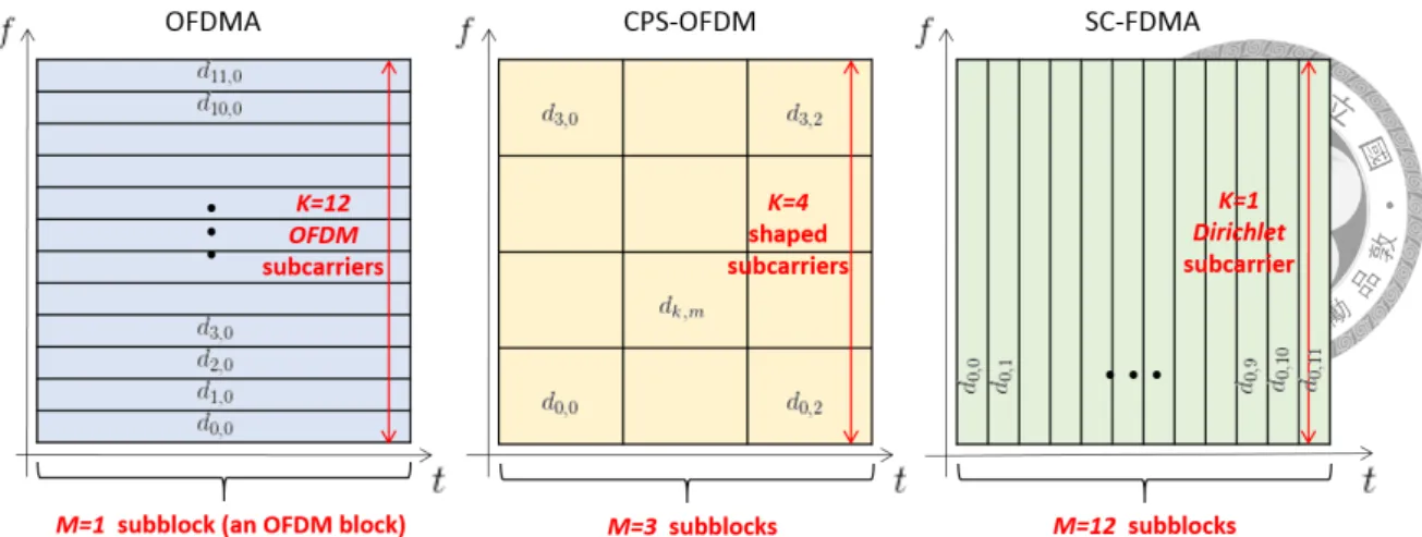
which can inherit the desired properties of tight spectral containment and reducing PAPR from the GFDM [62]. This proposed waveform, called CPS-OFDM, endows every user with flexibility to determine its own circular pulse shaping in terms of K, M , and a0,0, while preserving frequency-domain orthogonality with other users in the system. The physical meanings of K and M are the number of shaped subcarriers and the number of subblocks, respectively. Three time-frequency structures depending on different K and M are illustrated together in Fig. 2.3, where CPS-OFDM can be considered as a generalized form of OFDMA and SC-FDMA.
In the following subsections, we will elaborate on the precoder implementation, the OSBEP, the VIP, and the NEP of CPS-OFDM. Based on these analytic derivations, we are able to formulate an optimization problem in Section 2.3.
2.2.1 CPS Precoder Implementation and Complexity Analysis
Three equivalent CPS precoder implementation methods and their complexity are studied in this subsection. The first is a direct implementation done by the matrix multiplication in (2.17). The second is referred to as a frequency-domain implementation with the prototype
Figure 2.3: Three time-frequency structure illustrations in which CPS-OFDM can be viewed as a generalized form of OFDMA and SC-FDMA.
shaping vector
p = WSa0,0. (2.20)
The third is called a characteristic-matrix-domain implementation with the characteristic matrix
Γ =√
S/ρ reshape (p, M, K) WHK, (2.21)
where ρ = ∥p∥22 denotes the energy of p. Note that a0,0, p, and Γ are invertible linear transformations of one another.
Frequency-Domain Implementation Method
In the frequency-domain implementation, we consider the CPS precoding matrix P com- posed of K submatrices, i.e., P = [P0|P1| · · · |PK−1], where the kth submatrix is Pk = [P]I
k, Ik = {kM, kM + 1, · · · , kM + M − 1}. According to (2.18), the kth submatrix of A, defined as Ak≜ [A]Ik, can be expressed as [35]
Ak ≜ [A]Ik = WHSCkMdiag (p) RWM, (2.22)
where R = 1K ⊗ IM is a repetition matrix and CkM defined as
C0 = IS, CkM =
0 IkM
IS−kM 0
,
is a downshift permutation matrix. Hence, the kth submatrix of P is obtained by
Pk = WSAk= CkMdiag (p) RWM, (2.23)
which can be interpreted as the spectrally shaped M -point DFT precoder applied to the kth subvector of the data vector d, i.e., dk = [d]I
k.
There is an another way to understand the frequency-domain implementation. Con- sidering that (2.18) can be equivalently written as
[ak,m]s= ej2πkMS s·(
[a0,0]s⊛Sδ[s− mK])
, (2.24)
the ith element of the (kM + m)th column vector of P is obtained by performing the S-point DFT on (2.24), i.e.,
[pk,m]i = [P]i,kM +m =
S−1
∑
s=0
[ak,m]se−j2πSis (2.25a)
= δ[i− kM] ⊛S
(
[p]i· e−j2πMim)
(2.25b)
= [p]⟨i−kM⟩
Se−j2πMmi. (2.25c)
By arranging [pk,m]i for all i∈ ZSand m∈ ZM together, we are able to observe
Pk =
0 IkM IS−kM 0
| {z }
CkM
diag (p) [IM · · · IM]T
| {z }
R
WM, (2.26)
which is the same as (2.23). Furthermore, (2.25c) clearly reveals that the proposed CPS precoding matrix can be regarded as a kind of GFDM modulation matrices.
Characteristic-Matrix-Domain Implementation Method
In the characteristic-matrix-domain implementation, we refer to the results in [44, Lemma 1(c)] for A, and by analogy derive the (kM + m)th column vector of the CPS precoding matrix P as
pk,m = 1
√Svec (
diag(√
M [WM]m )
ΓWKC¯k )
(2.27a)
= 1
√Svec (
diag(√
M [WM]m )
Γdiag(√
K[ WHK]
k
) WK
)
(2.27b)
=
√KM
√S vec(
diag ([WM]m) Γdiag([
WHK]
k
)WK)
(2.27c)
= (WK⊗ IM) vec(
diag ([WM]m) Γdiag([
WHK]
k
)) (2.27d)
= (WK⊗ IM)[
diag (vec (Γ))(
WHK⊗ WM
)]
kM +m, (2.27e)
where ¯Ck =
0 IK−k Ik 0
is an upshift permutation matrix. Therefore, the CPS precoding
matrix can be decomposed as
P = (WK⊗ IM) diag (vec (Γ))(
WHK⊗ WM
). (2.28)
With this form, the unitarity of the CPS precoding matrix can be easily identified, i.e., P is unitary if and only if| [Γ]m,k| = 1, ∀k ∈ ZK, m ∈ ZM. Interested readers may refer to [44, Theorem 1] for more details about unitary GFDM matrices.
In summary, the CPS precoded symbols on the OFDM subcarriers indexed byI can be produced with
s = WSAd (2.29a)
=
K∑−1 k=0
CkMdiag (p) RWMdk (2.29b)
= (WK ⊗ IM) diag (vec (Γ))(
WHK⊗ WM
)d, (2.29c)
whose building blocks are displayed in Figs. 2.4(a), 2.4(b), and 2.4(c), respectively.