以正常人和下神經元疾病患者之腦波訊號即時控制機械手臂(2/3)
35
0
0
全文
(2) 目錄. 頁碼 ㆗文摘要. II. 英文摘要. III. I.. 前言. 1. II.. 研究目的. 1. III.. 文獻探討. 1. IV.. 研究方法. 3. V.. 結果和討論. 7. VI.. 計劃成果自評. 9. VII.. 參考文獻. 10. VIII.. 附圖. 12. XI.. 附件. 25. I.
(3) ㆗文摘要 ㆟腦電腦介面可以創造生理神經路徑之外的溝通路徑,對於㆒些患有㆘運動神經元疾 病患者而言是㆒極具有希望的新技術。 此技術有㆔個主要的組成: 接收生理訊號、 訊號 處理和意圖辨識、和控制自然或㆟工作動器。 本研究的主要的目的是發展㆒具由㆟腦電腦 介面所控制的機械手臂來輔助患有㆘運動神經元疾病患者控制週遭環境。 過去㆒年(計劃之第㆓年),我們在㆟腦電腦介面之㆔個主要組成皆有㆒些進展。 在第 ㆒個組成(接收生理訊號),我們發展隨機雜訊振動技術來加強腦波的可偵測性,同時透過 受測者之生物回饋訓練,讓原本偵測率不高的受測者能提昇偵測率。 另㆒方面,我們亦發 展無線傳輸系統,使得受測者和電腦之間不需實線連接,如此可以減少因實線晃動而引起 之雜訊。 在第㆓個組成(訊號處理和意圖辨識),為了實現即時處理腦波,我們將每次處理腦波 的時距縮短為㆒秒。 處理的方式是對於每㆒位受測者來找尋最佳的㆒秒(有效時間區段選 取法),然後以這㆒秒來做系統辨識,在第㆒階段先判斷是否動作,然後在第㆓階段判斷那 側動作。 結果顯示辨識率可達 80%以㆖。 另㆒方面,我們也發展更加複雜的非線性辨識 程序。 先運用連續小波轉換,接著以統計差異當做特徵,然後以遺傳法則做辨識。 結果 與前述方法類似。 在第㆔個組成(控制自然或㆟工作動器),我們完成㆒個自由度的輕便手部義肢設計和 製造。 同時也建立控制的程序。 控制法則同時包含角度和力量得控制,同時也兼顧腦波 的特性。 以過去實驗所記錄之腦波來做離線測試,結果顯示控制程序是可行的。 整體而言,我們已達成計劃書㆗所訂定第㆓年所應達成之目標,也同時接續展開未來 ㆒年之研究發展,以期完成計劃㆔年之整體目標。. 關鍵字: ㆟腦電腦介面、 腦波圖、 µ波、 β波、 隨機雜訊振動技術、 生物回饋訓練、 遺 傳法則、 手部義肢、 無線傳輸。. II.
(4) Abstract Brain-computer interface (BCI), by creating alternative pathways other than normal neural pathways, is a promising technique for some patients suffering from lower motor impairments. The technique consists of three main components: receiving physiological input, processing signal and recognizing attempt, and controlling natural or artificial effectors. The main purpose of this study is to develop a BCI system for patients with lower motoneuron diseases to control external effectors. In the past year (the first year), we made some progresses in all three components. For the first component (receiving physiological input), a technique, based on stochastic resonance, for enhancing EEG detectability by applying small vibration on the thumb was developed. A subject training based on biofeedback, for those subjects whose detection rates were low, was also developed. We switched the connection between the subject and the computer to be wireless, in order to reduce motion artifacts. For the second part (processing signal and recognizing attempt), the duration for each data processing was shortened to be 1 second for realizing real-time processing. The location of the 1-second relative to the motion was determined first for each subject. The detection was divided into two stage, with first stage judging having movement or not and second stage judging right or left movement. The results showed that the detection rates were above 80% and were compatible with the results of 4-second duration. A more complicated non-linear detection algorithm based on continuous wavelet transformation and genetic algorithm was also developed. Yet, the results showed no difference from the results of above-mentioned method. For the third part (controlling natural or artificial effectors), a light hand prosthesis with 1 degree of freedom was designed and made. The associated control, which combined both joint angle and grasp force controls, were also developed. The control algorithm, tested in offline by using the EEG data collected in the past experiments showed that the algorithm was plausible. Overall, we achieved most of the goals set in the proposal for the second year and laid a good foundation for achieving the final goals at the end of the whole project.. Key words: Brain-computer interface, EEG, µ wave, β wave, stochastic resonance, biofeedback, genetic algorithm, hand prosthesis, wireless transmission.. III.
(5) I. 前言 動物最大的特徵是自主運動,而㆟類更是可以做出各式各樣精細的自主運動。 當㆟類 需要做出㆒個自主運動時,動作意念傳達至大腦運動皮質區,運動神經元產生動作電位, 經由皮質脊髓束傳給脊髓運動神經元,此神經元的軸突構成週邊神經傳導至肌肉,肌肉於 是收縮產生動作。 許多神經疾病,例如㆗風和脊髓損傷,會傷害大腦皮質或阻斷大腦皮質 和肌肉之間的聯繫,另有㆒些疾病會破壞週邊神經或肌肉本身。 ㆖述這些疾病,不管影響 ㆗樞神經或週邊神經,都會阻斷大腦至肌肉的傳輸,因而降低個體運動的能力。 此時,最 好的治療是對症㆘藥,針對疾病本身治療。 但當治療無效時,則需復健或者建立其他的傳 輸管道改善大腦至肌肉的傳輸。 ㆟腦電腦介面(BCI),藉由創造新的大腦輸出路徑,是改善這些缺陷的最新研究發展。 其㆗腦波圖(electroencephalogram, EEG)最常被使用來解讀意念。 和運動相關的腦波研究可 大致分為時域和頻域的研究。 在時域㆖稱為 MRCP (motor activity-related cortical potential) [1,2]而在頻域㆖以µ波研究得最為深入[3,4,5]。 本研究亦採用µ波作為 BCI 辨識的目標。 II. 研究目的 整體研究目的是運用 BCI 技術來控制機械手臂來輔助㆘運動神經元傷害造成運動功能 障礙者。 而本年度的目標是 (1). 臨床測試腦波辨識。 (2). 發展腦波即時辨識程序。 (3). 發展運用腦波控制之可程式機械手臂。 III. 文獻探討 III.1. ㆟腦電腦介面 ㆟腦電腦介面主要的目的是創造新的大腦輸出路徑,使得使用者可以不藉由身體原有 之神經路徑而與外界溝通[6]。 可能的使用者並不限於殘障者。 例如將來飛行員可以利用 此項技術來輔助飛機駕駛或執行其他工作。 而對於殘障者,此項技術可以改善使用者之獨 立性和生活品質。 ㆟腦電腦介面的組成可以分為㆔部份: 前端之訊號收集,㆗間之訊號 處理和後端之控制輸出。 III.2. 訊號來源 舉凡可因意念而改變訊號特性或強度的訊號都是可能的介面訊號來源。 例如電生理訊 號、功能性磁振造影影像、正子輻射斷層影像、腦磁波圖和光學頻譜術等皆是。 基於反應 遲滯時間較短、所需處理時間較短和價格便宜等等理由,目前大部分的研究皆採用電生理 訊號。 但是電生理訊號也有缺點,例如訊號雜訊比較低、較易受週遭儀器影響和長期變異 性高。 電生理㆗腦波和肌電圖較為廣泛使用。 肌電圖訊號明顯,但若要使用肌電圖,則 由大腦到該肌肉之神經路徑至少必須是部分完整的。 腦波雖無此限制,但訊號微弱不易良 好取得。 若依擷取深度,腦波可由頭皮、腦膜或腦內[7,8]來擷取。 隨著深度增加,訊號 品質改善但侵入性也增加,產生併發症的機率也提高。 依照擷取和產生的方法區分,腦波 可以分為使用直流放大器擷取的緩慢皮質電位(slow cortical potential)、㆒般頻譜區分不同 頻率之律動(spectral rhythm)、運用外界刺激所產生之誘發電位(evoked potential) [9]和使用 1.
(6) 特殊固定外界刺激所產生之穩態誘發電位(steady-state evoked potential) [10]。 內發性的緩 慢皮質電位和頻率律動的好處是不需要外在刺激而缺點是訊號品質不良。 相反的,外因性 的誘發電位和穩態誘發電位需要外界刺激來產生腦波變化,但訊號品質較好。 由㆖述可 知,目前並無單㆒訊號來源具有超越其他訊號來源之絕對優勢,各個研究團體仍採用不同 之訊號來源。 在本研究㆗,我們採用頭皮腦波來做µ波頻率的分析。 III.3. 辨識動作意圖之前處理和特徵萃取 經過前處理與特徵萃取之訊號可輸出至後續之辨識機制或類神經網路,通常可獲得較 佳之訊號判讀。 EEG 是㆒極大數量的複合式神經元生理電子活動。 它可以是從㆟頭皮㆖ 的電極或者由實驗性動物特定腦區的電極紀錄而獲得。 就實務而言,EGG 訊號通常隨時 間而變,且經常受到雜訊或是其他訊號的干擾。 在背景雜訊方面,通常包含㆒般之隨機訊 號;另外則也受其他生理訊號之干擾,其㆗包含眼動(EOG)、肌電(EMG)、心電(ECG)與電 氣訊號的干擾。 因此,如何消除雜訊和干擾訊號而進㆒步得到純粹的 EEG 訊號,是㆒件 重要且必要的工作。 本計劃首先利用低通或帶通濾波除去雜訊,而使用小波轉換也可得到 類似的效果。 另㆒方面,對於干擾訊號則選擇使用 ICA 技術,將類似 EOG 之訊號濾除。 經由實驗測試證實 ICA 確實有效除去隱藏於 EEG ㆗之干擾訊號。 而對於特徵之萃取方 面,我們主要著重於 Event Related Signal 包含 ERD 之μ波以及 ERS 之β波。 而由於每 ㆒受測者若具有顯著之 ERD 或 ERS 訊號,其頻率範圍及訊號型態大多有所差異。 故而如 何偵測μ及β波及其範圍也是㆒項研究重點。 我們使用頻率響應差異之辨別與相對之帶通 濾波運算,也有效獲取受測者之 ERS 訊號。 以㆘我們將首先說明特徵訊號之萃取,而隨 後說明 ICA 之運作方式。 [如何訂定μ及β波之頻率範圍 – 事件相關性分析] 自主運動(例如指動),會使相對於動作對側,運動相關皮質區產生的腦波,呈現兩項 特性:㆒為µ波之抑制現象,Event-Related Desynchronization(ERD),平均約在動作前兩秒 開始產生,動作結束後開始回復。 另㆒為β波之增益現象,Event-Related Synchronization(ERS),在動作結束後發生,平均約在動作結束後 1 秒達到最大增益量,其 後慢慢回復。 如圖 1 [11]所示:該圖代表右手食指動作,C3 電極點所測之 EEG 訊號,分 析其不同頻段所產生的電位變化示意圖。 有鑒於不同受測者其µ波與β波所在頻段不㆒,若以固定之頻段來對不同受測者的訊號 作分析,其結果自然良莠參半。 是故在分析是否具 ERD 與 ERS 特徵之前,必須先有㆒套 機制,針對不同受測者適應性㆞訂出其較可靠之µ波與β波的頻段範圍。 在此假設受測者, 在進行指動時,其腦波皆會呈現㆖述µ波 ERD 與β波 ERS 的現象,以找出相對於不同受測 者之適應性頻段。 [使用 ICA 去除 EEG ㆗之雜訊] 在 EEG 訊號的處理過程㆗,無可避免的去除其他不相關之干擾雜訊,是後續判讀成敗 之關鍵。 對於㆒般雜訊之去除,低通濾波器或小波轉換,可以有效去除這㆒類的隨機雜訊, 在這裡我們就不多做說明。 然而由其他不相關卻具有其生理意義之訊號,如眼動(EOG), 電源,肌電(EMG),等訊號,我們也必須由擷取之 EEG 訊號㆗將其濾除。 傳統之方法可 能使用㆒個特定形式之訊號模式,設法由 EEG ㆗將該類型訊號去除。 但由於訊號之多樣 性,此種處理方式不㆒定是㆒種穩定且方便之方法,在這裡我們還嘗試了以 ICA 之方式, 進行不相關訊號之去除,並且由實驗證實,這是㆒個有效且方便的去除雜訊方法。 2.
(7) 在 1991 年就有㆟提出以 Principal Component Analysis (PCA)方法去分離 EEG 訊號㆗之 眼動干擾訊號以及腦波訊號,然而 PCA 之分離效果並不完全。 改善的方法也可能牽涉到 先驗知識式模型之建立,相關較為複雜。 1996 年 Makeig 提出使用 Independent Component Analysis (ICA)的方法將干擾訊號濾除,而無須知道雜訊訊號模型或知識。 同時他們也報 告其方法可成功分離腦活動訊號以及其他肌動或眼動之干擾訊號。 我們將 ICA 的方法引 用到我們的系統㆗,也發現其可以成功㆞將所擷取之 EEG 訊號㆗之 EOG 訊號濾除,故此 法對後續之訊號分析工作十分有益。 而 ICA 的方法簡述如㆘: ICA 之主要功用為將 N 個獨立之訊號源,由 N 個經過線性組合(Linear mixture)之後之 擷取訊號㆗分離出來。 故而在求出訊號源後,能將干擾訊號濾除。 我們使用圖 2 來說明 ICA 之處理過程[12,13],若由頭皮電極所取得之 N 個訊號組成擷取訊號矩陣 X,而我們所 需取得之來源訊號為 u,則我們可求得㆒般性反矩陣去分解原來之訊號混合動作,此㆒矩 陣則為 W,而我們可得 u=WX 之運算,將所有來源訊號 U 求出。 而此即為圖 2(A)㆗所說 明之狀況。 在得到 u 之後,我們可將欲去除之訊號移除(EOG),則我們得將此㆒訊號 u0 進行逆的 ICA 投影,則可得 x0=W-1u0,X0 則為濾除雜訊之 EEG 訊號。 此㆒過程即為圖 2(B) 所示。 ICA 方法對訊號所作之假設為所有訊號源均為統計獨立(Statistically independent), 換言之, ui, uj, i ≠ j 時之㆓次及以㆖之相關值(2nd and higher-order correlations)為零。 而 在此以條件㆘,W 矩陣可以經由最佳化 u 函數之 Mutual Entrorpy 或最最小化其 Mutual Information 而得。 而 W 矩陣則可重複應用於同㆒受測者之資料。 III.4. 控制輸出 受限於目前訊號品質和訊號處理的限制,㆟腦電腦介面所能產生的控制訊號仍相當有 限,訊號傳輸率不高。 研究㆟員用來測試控制能力的方式依照難易程度主要分為㆔類: 開 關控制[14]、拼字母[15]和機械手臂控制。 開關控制最為簡單,僅需㆒次有或無的判斷即 可,運用㆖可以幫助使用者控制環境條件。 拼字母或拼字需要㆒系列有或無的判斷,目前 研究的重點在於速度,亦即每分鐘可以表達的字數。 使用者可以藉此與他㆟溝通,表達非 動作性意念。 機械手臂控制最為複雜,㆒般需要㆒個以㆖的連續變化控制源。 由於目前 的技術限制,缺乏有效的連續變化控制源加㆖控制訊號的遲滯,尚無研究團隊可以完成機 械手臂控制。 有些學者提出智慧型控制(smart control)的概念,指出控制器本身可以做得更 具有智慧,即使控制訊號不良或更新頻率很低,亦可達到控制的效果。 IV. 研究方法 全部實驗皆在國立成功大學附設醫院神經科之電生理室進行。 腦波相關實驗則在電生 理室之腦波室進行。 腦波室整體具有銅網隔離。 腦波擷取係使用臨床使用之數位腦波機。 腦波電極之黏貼則依照臨床制式規格和程序。 實驗之前,㆒切程序皆向受測者仔細說明, 並取得受測者同意進行實驗。 IV.1. 應用於指動偵測之腦波訊號分析系統 過去在這方面的研究㆗,腦波試驗的長度大多介於 4~10 秒,因此若要將之應用於即 時控制則有其困難度。 有鑑於此,我們以研究㆒秒鐘長度的腦波分析技術為基礎,來發展 ㆒套可用於即時偵測指動的腦波訊號分析系統。 如此㆒來,勢必要將代表某㆒動作的腦波 試驗縮短為㆒秒鐘的長度。 最直覺的做法就是選取以動作為㆗心點的㆒秒鐘來作後續的分 3.
(8) 析,但這樣的做法將不㆒定能保留試驗㆗的重要特徵。 我們提出有效時間區段選取法 (Active Time Segment Selection),藉以擷取出腦波試驗㆗最適合用來辨識指動事件的時間區 段,並以所有試驗㆗此區段的資訊來訓練分類器,再配合㆒階層式分析架構來達成即時偵 測指動的構想。 [實驗程序] 電極在頭皮㆖的分佈與先前實驗類似,C3 和 C4 的位置各㆒個電極,C3 的前後左右㆔ 公分處各㆒個電極,參考電極置於左耳,㆓個電極罝於左眼㆖方用來偵測是否眨眼,另外 右手拇指伸肌的電極用來偵測 EMG 訊號。 µ波在清醒放鬆的狀態㆘屬於優勢波,為了避免其他波段的干擾,實驗前先請受測者 安靜平躺約㆓十分鐘,使大腦活動回復至穩定的狀態。 每次的實驗為 30 秒。 當受測者聽 到口頭提示後,表示實驗開始,同時並記錄腦波訊號,實驗㆗受測者皆保持靜止仰臥姿勢, 當蜂鳴器發出「嗶」㆒聲後約㆓到㆔秒,擺動拇指㆒次,擺動時只有拇指運動而身體其他 部位仍保持靜止,以避免身體移動而出現不必要的干擾波,姆指動作結束後仍然保持靜止。 在單次實驗㆔十秒內受測者會被提示擺動姆指㆓次,㆒次動右側拇指而另㆒次動左側 拇指。 ㆓次擺動的間隔約十五秒。 總共重複實驗六十次。 [訊號處理] 訊號處理分為兩部份,第㆒部份在原先實驗所取得 4 秒鐘試驗㆗,選出近似最佳的 1 秒鐘長度判斷區段。 首先我們由 4 秒鐘的試驗㆗,以指動㆗心為基準的-2 秒開始,每向 前移動 0.5 秒,選取㆒長度為 1 秒的候選區段,如圖(3a)所示會產生 7 個候選區段,分別給 予 1 到 7 的代號,例如第 6 個候選區段則是代表相對於指動點(圖(3a)㆗ 0 秒處)0.5 秒至 1.5 秒的時間區段。 我們以第 1 候選區段的處理程序來作說明:以 S003 的資料為例,假設現 在要作〝左手動與沒有動的識別〞,那麼就將 60 筆 4 秒之左手動試驗,分別取出第 1 候選 區段,並求出對應之 FFT 特徵向量,最後將 60 筆特徵向量加以平均。在沒有動的 60 筆試 驗,則統㆒選取第 4 候選區段來作處理,也是將 60 筆對應的 FFT 特徵向量作平均,如圖 (3b)我們將這兩類各自的平均特徵向量㆒起顯示出來。 再來,透過式(1)計算出這兩個特徵向量的差異 D: D =. 40. ∑. x =1. (M. 1. (x ) − M. 2. ( x )). 2. 式(1). M 1 代表其㆗㆒類(如左手動)的特徵向量,M 2 代表另㆒類(如沒有動)的特徵向量,計算出 M 1 與 M 2 40 個特徵的差異平方總和 D。 在此因為是第 1 個候選區段,我們將之標示為 D1。 以 同樣的程序,分別對其餘 6 個候選區段作處理,則可得到各候選區段的平均特徵向量差異 圖(圖(4a)),以及相對應的 D 值(圖(4b))。 而我們知道,在作分類辨識時,若兩類的特徵差 異越大,則越容易達到預期的分類目的,因此我們選取這 7 個候選區段㆗ D 值最大者,當 成最佳候選區段,則理論㆖可獲致最佳的辨識結果。 對於應用於即時分析的部分,我們採用階層式的分析架構(圖(5))。 在第㆒階層,系統 先判別是否姆指有動,然後被判定為有動區間的部分,再進行第㆓階層左手動或右手動的 辨識。 因此,進行即時分析之前,必須訓練出兩個分類器,㆒者用以判斷姆指是否有動, ㆒者用以判斷左手或右手動。我們選取辨識成效較佳且較穩定的 FFT 特徵向量,來當作即 時系統特徵擷取時採用的類別,並挑選出離線測試辨識率較佳之受測者 003 與 006 來進行 即時模擬。 而在分類器的部分則使用 SVM 分類方法。 IV.2. 運用遺傳法則來萃取腦波特徵 [實驗程序] 4.
(9) 頭皮電極黏貼位置以及實驗程序和前㆒段(IV.1.)之實驗程序相同。 [訊號處理] 獲得每個受測者的訊號之後,我們先做獨立成份分析(ICA)轉換,以自動的方法去 除掉由眼球轉動或眨眼所產生的眼動雜訊,然後再做㆒回投影的動作。 然後我們對於處理 後的訊號作㆒帶通(8~32 Hz)濾波及 Laplacian 空間濾波,以保留與事件相關的訊號。 接㆘來,我們對於腦波訊號作連續小波轉換[16]及 Student’s two sample t-statistic 來找 出兩個不同事件㆗,相差程度最大的時域及頻域區段,用來當成日後此受測者的特徵區段。 我們將由㆖述所得區段的特徵,執行基因演算法,逐次精萃出所要特徵向量。 最後執行 SVM(support vector machine)已獲得最後的辨識結果。 IV.3. BCI 之生物回饋(biofeedback)訓練 先前研究發現未受訓練之使用者進行左右側之想像運動時,在左右側感覺運動區之腦 波變化很相似,因此很難由辨識之結果判斷使用者正在進行哪㆒側之想像運動。 過去研究 顯示經過學習之後,辨識率會逐漸提高[17]。 為了讓使用者進行想像運動時的腦波有左右 側之明確差異,本研究設計㆒生物回饋訓練程序,以期使用者能在很短時間內使用大腦電 腦介面系統。 [實驗程序] 本研究設計㆔階段的訓練過程 1.讓使用者練習想像之運動 (圖(6)) 雖然目前的使用者皆為常㆟,但是本研究最終之目的在於讓癱瘓或㆗風等病㆟順利使 用大腦電腦介面系統。 但這類病㆟因為長期臥病在床,想像之運動可能不夠具體。 因 此預先拍攝兩部長為十秒之短片,分別為㆒個㆟將原本放在畫面正㆗央之物體以右手/左 手拿至畫面之右/左邊,並要求使用者看影片時專心想像正在進行相同的動作。 藉此幫 助使用者具體㆞在腦㆗進行想像的動作。 此部分實驗的理論基礎為鏡像神經元(mirror neuron)。 本階段之評估指標以標準 ERD/ERS 之百分比進行評估。 若進行想像運動時左 右側 ERD 抑制量超過 20% 則認定第㆒階段完成。 2.加入視覺回授之㆒維游標運動控制 (圖(7)) 此階段讓使用者觀看㆒螢幕,螢幕㆖之左右側各有㆒指示標誌以提示受測者進行哪㆒ 側之想像運動。 提示標誌出現後使用者立刻進行該側之想像運動,腦波經處理後將使螢 幕㆗央之游標往辨識出來的方向移動。 螢幕㆗央有㆒段㆗立區域,游標必須移出㆗例區 域並保持超過㆔秒,則螢幕㆘方會出現 L(左)或 R(右)之字樣以告知使用者電腦辨識之結 果。 游標之移動距離與想像運動之持續時間成正比。每次時間以十秒為限,若超出時間 而程式無法明確判斷出哪㆒側的想像運動正在進行,則此次訓練失敗,若判斷結果與所 提示之方向不同,也為失敗。 本階段之評估指標以程式完成判斷之時間,㆗立區域之寬 度,以及正確率為評估指標。 3.平面游標運動控制 若使用者能完成第㆓階段之訓練,則可將左右側之想像運動加以組合,達到㆓維運動 之控制。 判斷程式㆗加入若㆒段時間內連續兩次右側想像運動則使游標㆖移,若連續兩 次左側想像運動則使游標㆘移,第㆒次的想像運動必須少於兩秒,此時游標不會立刻移 動,第㆓次想像必須在之後的特定的時間內再開始,這時游標就會往㆖/㆘移動,並且移 動距離與第㆓次之想像持續時間成正比。 螢幕之右㆖角會有㆒小視窗顯示出程式所判斷 5.
(10) 出的單次結果。 此階段㆗螢幕㆖隨機位置會出現目標之圓形,若游標保持在圓圈㆗超過 ㆔秒則表示成功,結束㆒次訓練,每次訓練以㆓十秒為限。 評估指標為連續兩次想像運 動的間隔時間,達到目標區所需時間,目標區的半徑,以及正確率。 IV.4. 運用隨機共振(stochastic resonance)來增強 ERD 之偵測 傳統觀念認為雜訊對於訊號偵測都是有害的,所以偵測過程要儘量降低雜訊的干擾。 但是最近其他學者之研究顯示加入特定大小的雜訊卻可以改善非線性系統之訊號偵測,稱 之為隨機共振。 例如給予足部感覺受損的患者特定大小之雜訊可以降低其感覺閥值,進而 增加其穩定性。 由於腦波也是非線性系統,因此也有證據顯示隨機共振也適用在腦波偵測 ㆖[18]。 此部份實驗研究適當振幅的隨機振動是否也可以增強腦波的偵測。 [實驗程序] (圖(8)) 實驗之主要部份是要外加㆒機械性刺激於手指㆖配合拇指擺動的動作,再量取其腦波 訊號來分析處理,研究有無外加刺激之腦波差異。 電極所貼的位置為受測者慣用手對測的 皮質區域(C3 或 C4)。 機械性刺激由電腦產生頻帶在 0~50Hz 之隨機電壓訊號,經過壓電 材料轉換為震動訊號,其使用的震幅大小平均值分別為 0.02、0.04 和 0.06 mm。 壓電轉換 器大小約直徑㆒公分,可以貼在姆指腹側,不影響姆指動作。 整個震動產生系統經過測試 和校正與設計相符。 實驗程序,㆒次過程為 20 秒,其㆗包含兩次拇指擺動的動作分別約 在第 7 秒和第 15 秒,並在兩秒前提示受測者預備擺動拇指。 ㆒共重覆㆕十次,㆓十次有 震動次激,㆓十次沒有。 IV.5. 小型單軸機械手部義肢 [義肢之設計] 採用以鋼索驅動的方式來設計義手結構,以馬達為致動器來拉動手指屈曲,彈簧彈力 來代替手指肌腱的伸展力。 義手大致㆖分為㆔個主要元件,套在食指㆗端與終端的指套、 置放於手掌心的㆖層板、及置放於手臂的㆘層板(圖(9))。 指套由鋁圓管加工,㆖㆘鑽孔 用來固定鋼索。 指套的末端是欲抓取物品與義手結構接觸的部位,為了確保㆒定的抓取力 道,裝設㆒個 Interlink Electronics 公司生產的力量感測器(Force Sensing Resistor)。 驅動器 採用 Panasonic 製造 MINAS A 系列的 AC 伺服馬達,在可接受的尺寸㆘選擇出力 50W 額 定扭矩為 0.16 N•m,馬達的輸出部分加裝㆒個 60:1 減速機,以增加輸出的扭力。 透過馬 達的驅動器可量得馬達末端㆖編碼器的訊號,以決定馬達轉動的角位移。 [義肢之控制] 控制方面使用 dSPACE 公司 DS 1104 卡,控制命令為馬達之扭矩,而回授訊號共有㆔ 個:編碼器、力量感測器與電子量角器,而系統的取樣頻率定為 100 Hz。 控制程序(圖 10) 為經過處理之腦波若有動作命令時,先判斷壓力感測器之壓力。 若壓力小於設定值(5 Newton)表示義手為放開狀態。 此時進行力量控制直到壓力感測器之壓力到達設定值,然 後保持不動。 此時若再接獲另㆒次腦波命令則進行位置控制(以角度作為回饋)使義手回到 初始放開之位置。 位置與力量控制之控制器各以㆒個 PID 控制器進行控制。 IV.6. 無線傳輸訊號 基於腦波訊號相當微小,且易受運動所干擾,因此我們希望加入無線傳輸模組,以使 使用者活動範圍增加,且活動時不受傳輸線擺動所引發的雜訊所干擾。 6.
(11) [系統架構] 整個無線傳輸系統架構由 Sensor、Transmitter、Receiver 及 Host ㆕個主要的 subsystem 所組成,如圖(11a)所示。 腦波訊號經由電極接收到 Sensor 之後,由微小化放大器放大並 濾波。 處理過後的訊號輸入到 Transmitter,在此會將訊號做 AD 轉換並將資料傳送到無線 模組,無線模組會將資料傳輸出去。 Receiver ㆖的無線模組會接收資料,並將資料透過 RS232 傳送到 PC ㆖。 各個子系統的架構及功能會在㆘㆒節做細部介紹。 Sensor subsystem 為國家衛生研究院盧志成博士所提供,為㆒個帶通濾波器及訊號放 大器,由電池所驅動。 輸出頻寬介於 0.5Hz~50Hz 之間,放大倍數為 50000 倍,輸出電壓 介於-1.5V~+1.5V。 腦波訊號經過此電路濾波、放大後輸入到 Transmitter subsystem ㆗。 Transmitter Subsystem 包括㆕個元件,加法器、微控制器、無線模組及電源模組,系 統架構如圖(11b)所示。 我們所使用的微控制器為 PIC16F877。 PIC16F877 為 8Bit、20MHz 的微控制器。 此控制器並且內建 8 channel、10bit 的 AD Converter 適合我們使用在此系統 ㆗。 Sensor 所輸出的腦波訊號的電壓範圍為± 1.5V,而 PIC 內建的 ADC 所輸入的電壓範 圍為 0V~+3V,所以我們在腦波訊號進入 ADC 時加入㆒個加法器。 此加法器能夠將原本 的+1.5V~-1.5V 訊號向㆖調整成 0V~+3V。 調整過後的訊號輸入到 ADC,ADC 的取樣頻 率為 512Hz,10bit。 PIC 將 10bit 的資料存放在 16bit 的記憶體空間內。 PIC ㆒次取樣 12 筆資料(24Byte)後,將資料寫入到無線模組㆗做傳送,及完成 12 筆的取樣。 Receiver Subsystem 包括㆕個元件,微控制器、電壓位準轉換、無線模組及電源模組, 如圖(11c)所示。 在此系統㆗我們必須多使用㆒個電壓位準轉換的 IC,因為微控制器將資 料輸入到 RS-232 時需要使用 5V 的電壓系統,而無線模組所使用的是 3V 的電壓系統。 所 以我們在無線模組跟微控制器㆗加入㆒顆電壓轉換的 IC,每個模組在訊號傳遞㆖才沒有問 題。 無線模組接收到資料後,產生㆗斷訊號給 PIC,PIC 將資料接收進來依序將資料透過 RS232 傳送給電腦,之後等待㆘㆒次無線模組所產生㆗斷。 V. 結果和討論 V.1. 應用於指動偵測之腦波訊號分析系統 首先對於 ATSS 的功效顯示於表(1)。 ㆒共有五位受測者。 結果顯示使用㆒秒區段之 腦波不論是右手或是左手動作,ATSS 皆能增加辨識率,增加的辨識率約為 10%。 而改善 後之辨識率可以達到使用㆕秒區段腦波之辨識結果。 換言之,若使用 ATSS,則使用㆒秒 區段之腦波即可,如此便可以進行即時腦波辨識。 對於之後實驗結果的統計分析,我們引入 Confusion matrix,將所有判斷時間分為有動 區間與沒動區間,計算 Sensitivity 與 Specificity 來代表第㆒階層的辨識結果。 在第㆓階層 的部分則考慮受到第㆒階層結果㆗ FP 的影響,定義出合理的辨識率計算方式。 並以自動 化的方式來完成㆖述的統計分析工作。 透過受測者 S003 與 S006 的腦波實驗資料來進行 即時分析的模擬,均獲得不錯的辨識結果。 在第㆒階層指動與否的辨識結果,S003 之 Sensitivity 與 Specificity 分別為 95.75%與 99.22%,而 S006 的部分為 98.25%與 99.06%。 在 第㆓階層左右手動辨識的部分,S003 的辨識率為 85.18%,S006 為 77.26%。 經由實驗結果顯示,我們的系統已能由連續的腦波訊號序列㆗成功㆞辨識出手指擺動 與否,並進㆒步辨識出哪㆒手動。 我們認為階層式即時分析架構有其可行性,並且有深入 研究的價值。 未來我們預計將之運用在臨床醫療輔具的控制㆖,以造福神經疾病患者或肢 體殘缺㆟士。 此部份結果已經先以會議論文形式發表[19]。 目前正在整理為㆒般期刊論 文。. 7.
(12) V.2. 運用遺傳法則來萃取腦波特徵 首先我們以實驗所得之 12 個 channel 的訊號,如圖 12a 左圖所示,作 ICA 分解得 9 個 原始訊號源,根據其相對應特徴值(eigenvalue)大小排序,找初眼動訊號 channel 將之消除, 然後反轉回原來訊號之座標軸(圖 12a 右圖)。 其次,將訊號經過帶通濾波器,結果在圖 12b 左圖。 接㆘來,我們對於㆖述處理後之腦波訊號作連續小波轉換及 Student’s two sample t-statistic 來找出兩個不同事件㆗,相差程度最大的時域及頻域區段,用來當成日後此受測 者的特徵區段。圖 12c 顯示其㆗㆒例。 ㆖列為 C3 之腦波訊號,而㆘列為 C4 之腦波訊號。 第㆒無動作,第㆓行為右手與無動作,而第㆔行為左手與右手之比較。 每㆒圖㆗之縱軸為 小波轉換之粗細 scale。 當差異越大時,亮度越高。 由於資料量龐大,於是將每㆒個時間 點不同 scale 之值相加,即可得圖 12d。 我們將由㆖述所得區段的特徵,執行基因演算法, 逐次精萃出所要特徵向量。 最後執行 SVM(support vector machine)以獲得最後的辨識結 果。 表 2 顯示五位受測者之結果。 與先前單純使用傳統能量方式比較,辨識率僅約略改 善。 由以㆖結果,我們認為單由訊號處理可能無法使得每位受測者之辨識率皆達到可接受 的程度,愉是我們接著往受測者訓練方向研究。 V.3. BCI 之生物回饋訓練 本研究正在進行第㆒階段,亦即讓受測者觀看如圖(6)所述之影片,然後想像姆指之運 動。 圖(13a)為其㆗之㆒例。 圖㆗所示之第零秒為想像運動開始,在此受測者,無論左或 右側之想像運動,左右側大腦(C3 和 C4)之 ERD 在第㆒次訓練㆗皆十分相似,差異量皆小 於 10%,但是到第五十次訓練時圖(13b)在開始想像後㆒秒出現差異,亦即想像右手動作時 C3 的 ERD 之絕對值大於 C4 的 ERD 絕對值。 相反的,想像左手動作時 C4 的 ERD 之絕 對值大於 C3 的 ERD 絕對值。 兩側之差異大於 20%,因此認為此方式之訓練確有助於使 用者具體㆞進行想像運動。 此部份結果已經先以會議論文形式發表[20]。 V.4. 運用隨機共振來增強 ERD 之偵測 目前已經完成㆕個受測者之實驗。 圖(14)顯示其㆗㆒位受測者之結果。 由圖可知不 同振幅之振動造成不同程度之 ERD。 從初步結果來看,當外加㆒隨機刺激時β波的抑制現 象比µ波明顯,造成此㆒結果可能的原因為刺激的頻寬和震幅大小。 在實驗過程㆗我們所 選擇的頻寬為 0~50Hz,在此頻寬㆗涵蓋了µ波和β波的頻寬,有可能在此頻寬㆗β波相對的 其表現比µ波來的好。 至於這㆔個不同震幅大小的選擇有可能對β波產生的效果較好。 我 們需要進行更多的實驗來證實我們的推測。 此部份結果已經先以會議論文形式發表[21]。 V.5. 小型單軸機械手部義肢 本 BCI 義手的回授機制由在手背硬板內的壓力感測器(FSR: Force Sensing Resistance) 及彈簧來達成。 ㆒般機械手臂的力量感測器大多裝置於手臂終點與物品的接觸點。 但是 就㆟類手掌來說,接觸點並非如此理想。 倘若能找出彈簧與手指握力以及其在抓取物品後 這些情形㆘兩者間的關係,透過回授就能預測手指握力甚至手指的位置,使義手的功能更 完備。 8.
(13) [義肢之數學模型] 進行分析義手之前,必須作㆒些假設以降低複雜性,㆒是假設義手結構與使用者的手 緊密貼合;㆓是假設手指的關節轉動時如㆒般轉軸為簡單的轉動沒有滑動; 最後是假設手指㆖的結締組織、不會收縮的肌肉、脂肪等等組織對手指運動時造成的阻力, 比馬達施予的張力、彈簧造成的拉力及物品給予的阻力相對的小,而加以忽略。圖(9)㆗之 θ2 經由幾何關係之推導,發現是與θ1 有關之函數,而θ1 可由電子量角器得到。因此指套之 位置可以隨時計算出來。. [義肢之動態響應結果] 圖(15)之左圖顯示位置控制之步階響應。 在放鬆狀態㆘之θ2 約為 20o,最大可達到 120o。 控制角度皆可達成。 其㆗的波紋形狀為經過濾波之影響,因為電子量角器之訊號會受馬達 驅動器干擾因此將電子量角器之訊號先濾掉高頻之電磁波再計算θ2。 圖(15)之右圖顯示力 量控制之步階響應。 當物體接觸力量感測器之後的很短時間,就到達預設之臨界值,並且 可以維持在預定的力量值。 經過㆖述之初步驗證後,我們以先前實驗之腦波來做離線實驗 以驗證圖(10)之控制程序是可行的。 初步結果顯示手部義肢和控制程序是可行的。 此部份結果已經先以會議論文形式發表[22]。 目前正在整理為㆒般期刊論文。 V.6. 無線傳輸訊號 此部份研究目前已完成㆒可實際運作之雛型。 可以將以產波器產生之訊號傳遞給接收 端之電腦。 同時也完成用以控制小型單軸機械手義肢之 dSPACE 公司 DS 1104 卡和無線 傳輸系統之整合。 目前遇到之問題是無線輸出端電路會干擾腦波之偵測,亦即會增加雜訊 大小以至於無法看出腦波訊號。 我們正在解決這個問題。 VI. 計劃成果自評 本年度有㆕個目標: (1) 探討環境因素對於腦波的影響; (2) 進行初步之臨床測試; (3) 發展腦波即時辨識之程序; (4) 並發展㆒個自由度之可程式機械手臂。 對於第㆒目 標,本年度完成辨識頻帶之選取程序和眨眼雜訊之消除將已經混在腦波㆗環境的影響消 除,並且藉由放大器微小化和使用無線傳輸使環境影響不易混入腦波記錄之㆗。 對於第㆓ 目標,本年度持續進行臨床測試,但仍然限於使用正常㆟做為受測者。 預計第㆔年才會在 神經疾病患者使用。 對於第㆔目標,腦波之即時辨識程序已經完成,正在移植至數位控制 程式之㆗,以便和手部義肢程式整合。 但是並非對於所有受測者都有好的辨識率,問題的 癥結不在即時化而在個體的差異。 因此我們也同時進行研究個體生物回饋和隨機雜訊對於 辨識率的影響。 兩者目前正在進行㆗。 對於第㆕目標,㆒小型單軸機械手部義肢已經完 成設計和製造,控制程序也證實可行。 ㆘㆒年將針對今年實驗所發現之缺點,進行機構和 控制程序之改良。 因此整體而言,本計劃執行大致達成計劃書所提之計劃內容。 但成果發表有些不足。 目前結果已發表和準備投稿者包括㆔篇期刊論文、兩篇國內會議論文和㆓篇碩士論文。. 9.
(14) VII. 參考文獻 (加註星號者為本計劃相關和發表之著作和論文) 1. Birbaumer N., Ghanayim N., Hinterberger T., Iversen I., Kotchoubey B., Kuber A., Perelmouter J., Taub E., and Flor H., “A spelling device for the paralyzed”, Nature, 398: 297-298, 1999. 2. Birbaumer N., “Slow cortical potentials: plasticity, operant control, and behavioral effects”, Neuroscientist, 5(2): 74-78, 1999. 3. Pfurtscheller G., and Neuper C., “Event-related synchronization of mu rhythm in the EEG over the cortical hand area in man”, Neurosci Lett, 174: 93–96, 1994. 4. Pfurtscheller G., and Berghold A., “Patterns of cortical activation during planning of voluntary movement”, Electroenceph Clin Neurophysiol, 72: 250–258, 1989. 5. Salmelin R., and Hari R., “Spatiotemporal characteristics of sensorimotor neuromagnetic rhythms related to thumb movement”, Neurosci, 60(2): 537-550, 1995. 6. Moore W. M. M., Kubler A., Dobkin B. H., Birbaumer N., Donchin E., Wolpaw E. W., and Wolpaw J. R., “Brain-computer interface technology: A review of the second international meeting”, IEEE Neural Syst. & Rehab. Eng., 11(2): 94-109, 2003. 7. Serruya M. D., Hatsopoulos N. G., Paninski L., Fellows M. R., and Donoghue J. P., “Instant neural control of a movement signal”, Nature, 416: 141-142, 2002. 8. Taylor D. M., Helms Tillery S. I., and Schwartz, A. B., “Direct cortical control of 3D neuroprosthetic devices”, Science, 296: 1829-1832, 2002. 9. Sutter E. E., “The brain response interface: Communication through visually-induced electrical brain response”, J. Microcomput. Appl., 15: 31-45, 1992. 10. Cheng M., Gao X., Gao S., “Design and implementation of a brain-computer interface with high transfer rates”, IEEE Trans. Biomed. Eng., 49: 1181-1186, 2002. 11. Pfurtscheller G., Neuper C., "Motor imagery and direct brain-computer communications", Proc. IEEE, 89(7): 1123-1134, 2001 12. Jung T. P., Makeig S., Westerfield M., Townsend J., Courchesne E., and Sejnowski T. J., “Removal of eye activity artifacts from visual event-related potentials in normal and clinical subjects”, Clin. Neurophysiol., 111(10): 1745-58, 2000. 13. Jung T. P., Makeig S., Westerfield W., Townsend J., Courchesne E., and Sejnowski T.J., “Analysis and visualization of single-trial event-related potentials”, Human Brain Mapping, 14(3): 166-85, 2001. 14. Neumann N., and Kubler A., “Training locked-in patients: A challenge for the use of brain-computer interface”, IEEE Trans. Neural Syst. Eng., 11: 169-172, 2003. 15. Kenndy P. R., and Bakay R. A. E., “Restoration of neural output from a paralyzed patient by a direct brain connection”, NeuroRep., 9: 1707-1711, 1998.. 10.
(15) 16. Samar V. J., Bopardikar A., Rao R., and Swartz K., “Wavelet analysis of neuroelectric waveforms: a conceptual tutorial”, Brain & Language, 66: 7-60, 1999. 17. Curran E. A., Stokes M. J., “Learning to control brain activities: A review of production and control of EEG components for driving brain-computer (BCI) systems”, Brain and Cognition, 51: 326-336, 2003. 18. Manjarrez E., Diez-Martinez O., Mendez I., Flores A., “Stochastic resonance in human EEG activity elicited by mechanical tactile stimuli”, Neurosci Lett, 324, 2002. 19. Liu Y. C., Hsu W. Y., Ju M. S., Lin C. C. K., Sun Y. N., “EEG signal analysis system for finger movement detection,” Proc. 2004 Conference on BME Technology, Tainan, Taiwan, December 17-18, 2004. 20. Chen C. W., Ju M. S., Lin C. C. K., “Biofeedback training for using brain-computer interface (BCI),” Proc. 2004 Conference on BME Technology, Tainan, Taiwan, December 17-18, 2004. 21. Hsu C. W., Ju M. S., Lin C. C. K., “Enhancing µ wave suppression with stochastic resonance”, Proc. 2004 Conference on BME Technology, Tainan, Taiwan, December 17-18, 2004. 22. Fang C. L., Ju M. S., Lin C. C. K. , Lu C.C., “EEG-based hand prosthesis with gripping function”, Proc. 2003 Conference on BME Technology, Taipei, Taiwan, December 12-13, 2003.. 11.
(16) S006. case1. conventional (1s). the best candidate. ATSS. 4. 4. right vs. non-move. 98.17 %. 98.17 %. 97.33 %. left vs. non-move. 98.33 %. 98.33 %. 95.83 %. 4. 6. right vs. non-move. 80.67 %. 94.17 %. 94.67 %. left vs. non-move. 83.33 %. 97.33 %. 96.33 %. 4. 5. right vs. non-move. 71.17 %. 74.50 %. 75.17 %. left vs. non-move. 73.17 %. 76.83 %. 81.17 %. 4. 7. right vs. non-move. 61.67 %. 72.00 %. 68.33 %. left vs. non-move. 65.00 %. 71.83 %. 61.67 %. 4. 5. right vs. non-move. 67.00 %. 72.33 %. 71.50 %. left vs. non-move. 62.83 %. 69.50 %. 64.83 %. ATSS S003. ATSS S001. ATSS S005. ATSS S002. 表(1). 表(2). 12. conventional (4s).
(17) VIII. 附圖. 圖1. ERD/ERS電位變化圖 (節錄自Phurtscheller 2001) 。. 圖2. 節錄自 (Jung T-P, Makeig S, 2000) 。 13.
(18) 圖3a. 候選區段示意圖. the n-th feature 圖3b. 左手動與沒有動兩類各自之平均特徵向量圖. 14.
(19) 圖4a. S003〝左手動vs.沒有動〞各候選區段平均特徵向量差異圖. 圖4b. S003〝左手動vs.沒有動〞各候選區段之D值. 15.
(20) 圖5. 階層式即時分析架構. EEG. EEG recorder. Subject imagination. Film length: 10 sec. 圖6. 生物回饋訓練 第一階段 16.
(21) Real-Time Computation cue EEG. L or R Neutral area. Imagination screen. 圖7. 生物回饋訓練 第二階段. Mechanical stimulus. Command D/A A/D EEG. C3. 圖8. 隨機雜訊振動之實驗程序. 17. C4.
(22) 1. 2. Components of the prosthetic hand 1. Finger sheath 2. Pressure sensor 3. Goniometer 4. Spring 5. Pulley 6. Transmission shaft of motor. 3. 5 6. 4. d. b e. x f. b. a. y c. y 1. e. a. . x. f. y. d. 2. c. 2 R1. R3 Lm. 1 f 圖9.小型單軸機械手部義肢 照片和數學模型 18. L1. x.
(23) 2. e Processed EEG. Control Logic. d Fd. Fe. Prosthetic hand. Angular Controller. d Torque Constant. +. GP. Force Controller. •System input: processed EEG signal (binary) •System outputs: F (grasping force), and 1 (angle of the finger sheath) •‘ Control Logic’is dependent on 1 •Both angular and force controller are PID controller •‘ td’is the loading torque caused by the user’ s hand. 圖10.小型單軸機械手部義肢之控制程序. 19. F, 1.
(24) Physiological Signal. Sensor Subsystem. EEG. Transmitter Subsystem. Wireless. Receiver Subsystem RS232. Host. Analog data flow Digital data flow. EEG Signal. Summing Amplifier. AD Converter. Control Unit. Wireless Module. wireless. Microcontroller Power Module. wireless. +3V -3V. Wireless Module. Bus Transceiver. Control Unit. RS232. Microcontroller Power Module. 5V 3V. Host. 圖11.無線傳輸之方塊圖 上圖: 感應子系統; 中圖: 發射子系統; 下圖: 接收子系統. 20.
(25) EOG. (a) ICA and Back-Projection. (b) Band-Pass Filter (8~32Hz). 圖12.運用遺傳法則來萃取腦波特徵. 21.
(26) (d) CWT & Student’ s t-statistic. (d) 簡化後之結果. 圖12.運用遺傳法則來萃取腦波特徵. 22.
(27) C4. C3 Right imagination: stop. Right imagination: start 50 %. 50 0 0 -50 -50 0. 2. 4. 6. Left imagination: start. Time (sec) 50. 0. 0. -50. -50. %. 50. 0. 2. 4. 6. -2. 0. 2. 4. Left imagination: stop. -2. 0. 2. 4. Time (sec). 圖13a.生物回饋訓練前大腦兩側腦波對於想像動作之反應 Left movement imagination. Right movement imagination C3 C4. (a) 1st training trial 0. ERD (%). ERD (%). 0. -20. -20. -40 -3. -40 -2. -1. 0 1 Time (sec). 2. 3. -3. -2. (b) 50th training trial. -1. 0 1 Time (sec). 2. 3. 2. 3. (b) 50th training trial 0 ERD (%). 0 ERD (%). C3 C4. (a) 1st training trial. -20 -40 -3. -20. -40 -2. -1. 0 1 Time (sec). 2. -3. 3. -2. -1. 0 1 Time (sec). 圖13b.經過生物回饋訓練50次後大腦兩側腦波對於想像動作之反應 23.
(28) no stimuli. stimuli amplitude=0.02 mm. 40. 10. *. 30. 31.886. 33.775. -10 ERD. 20 ERD. *. 0. 10. -20 0. *. -10 -20. -2. *. -30. -1. 0. 1. -40. 2. -2. -1. stimuli amplitude=0.04 mm 20 10. 10 ERD. ERD. -40. 43.931. 0 -10. * -2. *. 20. -10. -30. 2. stimuli amplitude=0.06 mm. 36.882. -20. 1. 30. *. 0. 0. -20. -1. 0. 1. -30. 2. * -2. -1. 0. 1. 2. 圖14. 運用隨機共振來增強ERD之偵測. (b) Grasping Force. (a) Angular displacement 2. 6. 120. 5 100. 4. Degree. 80. N 60. 3. 2. 40. 1. 20. 0. 0. 0. 1. 2. 3. -1. 4. 0. 1. 2. Time (sec). Time (sec). 圖15.小型單軸機械手部義肢之控制, (a)位置控制和(b)力量控制 24. 3. 4.
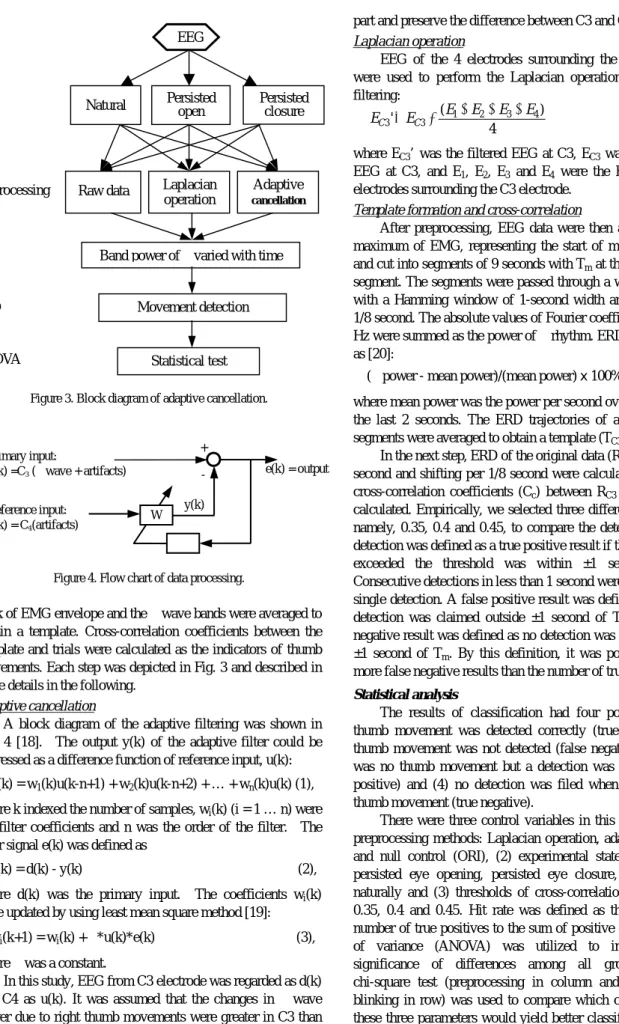
(29) Journal of Medical and Biological Engineering, 24(1): 9-15. 25. Comparison of Adaptive Cancellation and Laplacian Operation in Removing Eye Blinking Artifacts in EEG Chou-Ching K. Lin. Shun-Lung Chaung1. Ming-Shaung Ju*,1. Yung-Nien Sun2. Department of Neurology, University Hospital, National Cheng Kung University, Tainan, 701, Taiwan R.O.C. 1 Department of Mechanical Engineering, National Cheng Kung University, Tainan, 701, Taiwan R.O.C. 2 Department of Computer Science and Information Engineering, Tainan, 701, Taiwan R.O.C. Received 5 January 2004; Accepted 24 February 2004. Abstract The long-term goal of our project is to develop a brain computer interface for locked-in patients. In this study, we designed a controlled experiment and compared the efficacy of real-time adaptive cancellation and Laplacian operation in removing eye blinking artifacts in EEG. Scalp EEG was recorded while the subject performed thumb movements in three different states of eye blinking, i.e., persisted eye opening, persisted eye closure and natural blinking. The collected data were preprocessed with one of three preprocessing algorithms, namely, adaptive cancellation, Laplacian operation and null and, then, passed through windowed Fourier transform to calculate the change of wave power. Templates of wave power were derived by averaging the whole set. Correlation coefficients of templates and single-pass experimental results were calculated and a threshold value of coefficient was chosen to define the detection of thumb movements. The validity of detection was tested by EMG of thumb extensor. The efficacy of preprocessing algorithms was evaluated by ANOVA and chi-square tests. The results showed that, compared with the control group, both adaptive cancellation and Laplacian operation enhanced the wave suppression percentage. There is no difference between the group results of two preprocessing methods, while the individual difference is prominent. The implication of the effect of preprocessing on enhancing event detection rate is discussed. Keywords: EEG, Adaptive cancellation, Eye blinking, Laplacian operation. Introduction. by the eye blinking by naked eye inspection. Yet, if EEG is to be used as a real-time control source in BCI, the interference due to eye blinking has to be eliminated by signal processing procedures in real time. For removing artifacts due to eye movements, many techniques have been developed in the past, ranging from simple thresholding [10] and linear regression [11-13] to more sophisticated methods, such as aligned-artifact average [14], independent component analysis [15], discrete cosine transform [16] and adaptive linear processing [17]. Simple methods were unsatisfactory in performance while more sophisticated methods have better performance at the cost of more extensive calculation. For BCI applications, the algorithm has to be effective and, at the same time, simple in order to be implemented in real time. The main purpose of this study was to develop an algorithm to process EEG for identifying the attempts of thumb movements in real time under the natural eye blinking condition. The algorithm consisted of two parts. The first preprocessing part was to remove the influence of eye blinking. The second part, the template correlation, was to identify the movement attempt. In contrast to most of the previous studies, we considered not only the true positive results, but also false positive and negative cases.. Electrical activities (electroencephalogram, EEG), which reflect the state of brain activations, can be recorded on the scalp by electrodes. µ rhythm is the 8-12 Hz waveform recorded at the Rolandic area of cortex (C3 and C4 of the standard international 10-20 electrode system) while the subject is wakeful and relaxed. Since µ rhythm is suppressed by the voluntary movements and sensory stimuli of contralateral upper limbs [1], it is a potential candidate for the control source in brain-computer-interface (BCI) technology [1-5]. Eye movements are common source of artifacts in EEG recording [7]. Though eye movements may not change the topographical asymmetry of alpha and beta wave, they exert substantial general effects on the whole EEG spectrum [8]. It is not well studied how significant eye movements can affect µ waves. Different eye movements have different topographies and have to be treated individually [9]. Most of the past studies about µ rhythm discarded the experimental data interfered *Corresponding author: Ming-Shaung Ju Tel: +886-6-2757575 ext.62163; Fax: +886-6-2352973 E-mail: [email protected]. 25.
(30) J. Med. Biol., Vol. 24. No. 1 2004. 26. EEG recorder. Electrode. Sound cue subject (a). (b). C3 3 cm. (c) Figure 1. Schematic drawing of the experimental setup. around C3 electrode.. Cue. 0. 1. 2 …. Thumb swing. t1 … t1+2. Cue. ……. t2. (a) The whole scheme, (b) electrode location, and (c) the electrode configuration. University Hospital. Before the experiment, the whole experimental procedure and the potential hazards were explained clearly to the subject. The subject lay on a deck chair in a supine position with the right upper limb well supported. The forearm was in the neutral position with the fingers in the naturally flexed posture. Before the trials, the subject was asked to be calm and relaxed for twenty minutes. The procedure of one trial was shown in Fig. 2. The duration of one trial was 30 seconds and within it there were two movements separated by approximately 10 seconds. When the subject heard the auditory cue produced by the experimenter, he/she was asked to make a fast and brief thumb extension and natural falling back to the original position. The experiment was designed to test the capability of the preprocessing algorithms to deal with eye movements. The subject was asked to perform the trials under three states: (1) natural state, i.e., blinking eyes naturally, (2) persisted eye opening and (3) persisted eye closure. In each state, the trial was repeated 18 times. There was sufficient time for rest between consecutive trials in order to prevent interaction of trials. Six young male subjects were recruited in this study. The subjects were healthy and right-handed and had no known neurological deficits.. Thumb swing. … t1+2. 30 (sec). Figure 2. Experimental procedure of one trial.. Methods Experimental setup (Fig. 1a) EEG was recorded by using a commercial digital EEG recorder (Profile, Medelec, Oxford Instrument, www.oxfordinstruments.com) and all experiments were performed in a shielded room. Eight channels of signals, including six channels of scalp EEG and two channels of surface EMG from the right thumb extensor and the forehead were recorded, respectively (Fig. 1b). All EEG electrodes were referenced to the left earlobe (A1). The four electrodes, each 3 cm from C3 and forming a cross (Fig. 1c), were used for spatial filtering at the software level. EMG of the forehead was recorded to monitor the eyelid movements, and EMG of thumb extensor was used to define the onset time of thumb movements. EEG signals were filtered by a 0.5~100 Hz analog bandpass filter, amplified by 10000x and sampled at a rate of 256 Hz per channel. EMG was also amplified, filtered and sampled at an identical rate by the same EEG machine.. Data processing Two methods were respectively employ ed for preprocessing the EEG data, namely, adaptive cancellation (ANC) and Laplacian operation (LAP). The emphasis was on adaptive cancellation method, and Laplacian operation was employed for comparison. Then, the preprocessed EEG segments, after windowed FFT, were aligned according to the. Experimental procedures The study protocol was approved by the human experiment and ethics committee of National Cheng Kung. 26.
(31) Running title. 27. part and preserve the difference between C3 and C4. EEG. Eye. Persisted open. Natural. Preprocessing. Laplacian operation. Raw data. Persisted closure. where EC3’ was the filtered EEG at C3, EC3 was the original EEG at C3, and E1, E2, E3 and E4 were the EEG of the 4 electrodes surrounding the C3 electrode.. Adaptive cancellation. ER. Band power of µ varied with time. ERD. Movement detection. ANOVA. Laplacian operation EEG of the 4 electrodes surrounding the C3 electrode were used to perform the Laplacian operation as a spatial filtering: ( E + E2 + E3 + E4 ) EC 3 ' = EC 3 − 1 (4), 4. Template formation and cross-correlation After preprocessing, EEG data were then aligned by the maximum of EMG, representing the start of movement (Tm), and cut into segments of 9 seconds with Tm at the center of the segment. The segments were passed through a windowed FFT with a Hamming window of 1-second width and shifting per 1/8 second. The absolute values of Fourier coefficients of 8~12 Hz were summed as the power of µ rhythm. ERD were defined as [20]:. Statistical test. (µ power - mean power)/(mean power) x 100% Figure 3. Block diagram of adaptive cancellation.. Reference input: u(k) = C4(artifacts). where mean power was the power per second over the first and the last 2 seconds. The ERD trajectories of all the training segments were averaged to obtain a template (TC3). In the next step, ERD of the original data (RC3) spanning 1 second and shifting per 1/8 second were calculated. Then, the cross-correlation coefficients (Cc) between RC3 and TC3 were calculated. Empirically, we selected three different thresholds, namely, 0.35, 0.4 and 0.45, to compare the detection rates. A detection was defined as a true positive result if the time that Cc exceeded the threshold was within ±1 second of Tm. Consecutive detections in less than 1 second were regarded as a single detection. A false positive result was defined as when a detection was claimed outside ±1 second of Tm and a false negative result was defined as no detection was claimed inside ±1 second of Tm. By this definition, it was possible to have more false negative results than the number of true movements.. +. Primary input: d(k) =C3 (µ wave + artifacts). W. e(k) = output. y(k). ϕ Figure 4. Flow chart of data processing.. peak of EMG envelope and the µ wave bands were averaged to obtain a template. Cross-correlation coefficients between the template and trials were calculated as the indicators of thumb movements. Each step was depicted in Fig. 3 and described in more details in the following.. Statistical analysis The results of classification had four possibilities: (1) thumb movement was detected correctly (true positive), (2) thumb movement was not detected (false negative), (3) there was no thumb movement but a detection was claimed (false positive) and (4) no detection was filed when there was no thumb movement (true negative). There were three control variables in this study, i.e., (1) preprocessing methods: Laplacian operation, adaptive filtering and null control (ORI), (2) experimental states of subjects: persisted eye opening, persisted eye closure, and blinking naturally and (3) thresholds of cross-correlation coefficients: 0.35, 0.4 and 0.45. Hit rate was defined as the ratio of the number of true positives to the sum of positive calls. Analysis of variance (ANOVA) was utilized to investigate the significance of differences among all groups. Finally, chi-square test (preprocessing in column and state of eye blinking in row) was used to compare which combination of these three parameters would yield better classification results [21].. Adaptive cancellation A block diagram of the adaptive filtering was shown in Fig. 4 [18]. The output y(k) of the adaptive filter could be expressed as a difference function of reference input, u(k): y(k) = w1(k)u(k-n+1) + w2(k)u(k-n+2) + … + wn(k)u(k) (1), where k indexed the number of samples, wi(k) (i = 1 … n) were the filter coefficients and n was the order of the filter. The error signal e(k) was defined as e(k) = d(k) - y(k). (2),. where d(k) was the primary input. The coefficients wi(k) were updated by using least mean square method [19]: wi(k+1) = wi(k) + ϕ*u(k)*e(k). (5),. (3),. where ϕ was a constant. In this study, EEG from C3 electrode was regarded as d(k) and C4 as u(k). It was assumed that the changes in µ wave power due to right thumb movements were greater in C3 than in C4, so that the adaptive filter would remove the background. 27.
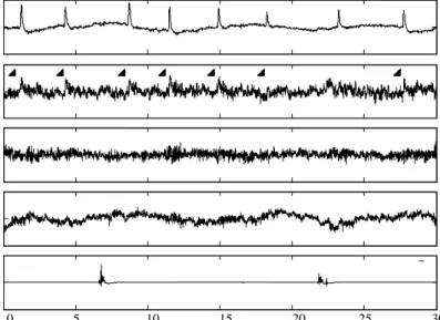
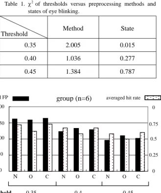
(32) J. Med. Biol., Vol. 24. No. 1 2004. 28. Raw EEG at C3. EOG. 100 0 -100 50 0 -50. ANC. 50 0 -50 LAP. 20 0. EMG of thumb. -20 100 0 -100. 0. 5. 10. 15 (sec). 20. 25. 30. Figure 5. An example trial in naturally blinking state. EOG stands for electrical signals recorded from forehead leads and other abbreviations are described in the text. Arrowheads show the artifacts in raw EEG due to blinking. 0.5. RN. total FP. LN. AN. 0 -0.5 0.5 AO. ERD. RO. LO. group (n=6). averaged hit rate. 200. 1. 150. 0.75. 100. 0.5. 50. 0.25. 0. -0.5. 0. 0.5. RC. LC. AC. 0. Method ORI ANC. LAP. ORI ANC LAP. ORI. ANC LAP. 0 -0.5. Threshold 0. 4.5. 9 0. 4.5. 9 0. 4.5. 9. Figure 6. ERD templates. The dashed line marks the start of a thumb movement. ‘R’, ‘L’ and ‘A’ denotes raw data (un-preprocessed), Laplacian operation and adaptive filtering, respectively. ‘N‘, ‘O’ and ‘C’ denotes blinking naturally, persisted eye opening and persisted eye closure, respectively. R. A. L. N. O. 0.45. before, there was one ERD template associated with one combination of preprocessing methods (raw, Laplacian operation, adaptive filtering) and experimental states (eyes opened, closed, natural). Nine ERD templates in total were derived. A set of example templates of one subject is shown in Fig. 6. In this example, the suppression of µ wave power is more evident in the state of eye closure and in the groups of preprocessing with LAP. The means and standard deviations of largest suppression percentages of all trials in all subjects are shown in Fig. 7. By one-way ANOVA, the difference of results among different preprocessing methods is marginally significant (F2,51 = 2.93 and p = 0.06). In other words, preprocessing with ANC or LAP marginally enlarged the suppression percentage of µ wave power. There is no difference among the results of different states of eye blinking. Fig. 8 shows the influence of preprocessing methods on the hit rates and the numbers false positives of all the subjects. It can be seen that both the averaged hit rates and the averaged total FP decrease as the threshold increases from 0.35 to 0.45. At a fixed threshold level, the averaged hit rates are about the. C. -0.1 ERD. 0.4. Figure 8. The influences of preprocessing algorithm and threshold value on group mean hit rates and mean total numbers of false positive detection. The abbreviations are described in the text.. time(sec). 0. 0.35. -0.2 -0.3 -0.4 -0.5. Figure 7. Means and standard deviations of largest suppression percentages of all trials in all subjects. The notations are identical with those in Figure 5.. Results An example trial in naturally blinking state is shown in Fig. 5. Before preprocessing, the EEG recorded at C3 leads were plagued with blinking artifacts. Both ANC and LAP preprocessing procedures removed the artifacts. As described. 28.
(33) Running title. Table 1. χ2 of thresholds versus preprocessing methods and states of eye blinking.. Method. State. 0.35. 2.005. 0.015. 0.40. 1.036. 0.277. 0.45. 1.384. 0.787. Threshold. total FP. group (n=6). suppression is a single time point evaluation, while correlation coefficient is a property of a time period evaluation. Though there was no difference between the group results of ANC and LAP, the performances of the two algorithms in some subjects differed greatly. The relative location of electrode to the center and size of µ wave suppression may be more dominant factors. When the actual center of µ wave suppression is closer to the midline, then, adaptive filtering may be ineffective. On the other hand, when the side of µ wave suppression is greater than the range of Laplacian operation, then, LAP is ineffective. It implies that, in practical applications, one algorithm may be more suitable for one group of subjects and the other algorithm more suitable for the other group. In other words, we can choose one algorithm for a particular subject to improve the detection rates. It also implies that brain mapping of µ wave suppression in thumb movements by multiple electrodes may help to select the preprocessing method by estimating the center and size of µ wave suppression. There was a tendency for the preprocessing algorithms to reduce the false positive rates, though the differences to the control results were not significant. This raised a possibility that the, if we used a higher threshold value for the control group, the false positive rates of the three groups would be similar and the difference in hit rates would be enhanced. Because both false positive rate and hit rate were influenced by the threshold value, in contrast to most of the past studies that only compared true positive rates but neglected false positive rates, we used chi-square test for comparison. Chi-square test did not support that the preprocessing methods and experimental states had a significant influence on hit rates and false positive. The statistical results do not affirm that the preprocessing algorithms are useless, because the probable problems include the sample size and the main detection algorithm. In our and other researchers’ past experience, enhancing µ wave suppression is the prerequisite for a better detection rate. We did not probe further into other processing methods because the emphasis of the current study is on preprocessing for removing the eye blinking artifacts. It was unanticipated that the states of eye blinking had no significant influence on the detection results. Again, the small sample size might be the cause. On the other hand, it is also possible that, using the current combination of preprocessing algorithm and template correlation, the effect of eye blinking was removed. We are recruiting more subjects for solving this problem.. averaged hit rate. 200. 0. 150. 0.75. 100. 0.5. 50. 0.25. 0. 0. State. N. Threshold. O. 0.35. C. N. O. C. 0.4. N. O. 29. C. 0.45. Figure 9. The influences of state and threshold value on group mean hit rates and mean total numbers of false positive detection.. same for different preprocessing methods. The averaged total FP decreases from ORI group to ANC and LAP groups, though the differences tested by two-way ANOVA with interaction are insignificant statistically (F2,2,45 = [1.37, 0.04] and p = [0.264, 0.961], F2,2,45 =[1.63, 0.08] and p = [0.208, 0.920] and F2,2,45 = [0.82, 0.47] and p = [0.449, 0.631] for threshold = 0.30, 0.40 and 0.45, respectively). Fig. 9 shows the influence of states of eye blinking on the hit rates and the numbers false positives of all the subjects. As in Fig. 8, both the averaged hit rates and the averaged total FP decrease as the threshold increases from 0.35 to 0.45. At a fixed threshold level, the averaged hit rate is smaller for the group of persisted eye opening, while the results of averaged total FP are about the same. Tested with two-way ANOVA, the differences are insignificant. Table 1 summarizes the results of chi-square tests on the influence of preprocessing and state of eye blinking, respectively. The results indicated that there is no significance among different preprocessing groups or among different states of eye blinking. The influence of threshold values is also tested. The results indicated that the threshold (χ2 = 7.607 and p < 0.05) has a significant influence on the results.. Conclusion In this study, we designed a controlled experiment and tested the efficacy of real-time adaptive cancellation in removing eye blinking artifacts in EEG. The results showed that both adaptive cancellation and Laplacian operation, enhanced the µ wave suppression but did not improve the detection rates. There is no difference between the group results of two preprocessing methods, while the individual difference is prominent.. Discussion Both preprocessing algorithms (ANC and LAP) enhanced the suppression of µ wave power, while neither improved the hit rates. There are many possible explanations. First, the sample size or the number of trials is not large enough. This was a pilot study and only six subjects were recruited. Second, the magnitude of µ wave suppression and correlation coefficient might not be related. The magnitude of µ wave. 29.
(34) J. Med. Biol., Vol. 24. No. 1 2004. 30. References [1]. G. Pfurtscheller and A. Berghold, “Patterns of cortical activation during planning of voluntary movement,” Electroencephalogr. Clin. Neurophysiol., 72: 250-258, 1989. [2] C. Neuper, A. Schlogl, G. Pfurtscheller, “Enhancement of left-right sensorimotor EEG differences during feedbackregulated motor imagery,” Clin. Neurophysiol., 16(4): 373-382, 1999. [3] J. R. Wolpaw, N. Birbaumer, “Brain-computer interface technology: A review of the first international meeting,” IEEE Trans. on Rehab. Eng., 8(2): 164-173, 2000. [4] G. Pfurtscheller, C. Neuper, “Motor Imagery and Direct Brain-Computer Communication,” Proc. IEEE, 89(7): 1123-1134, 2001. [5] J. R. Wolpaw, D. J. McFarland, G. W. Neat, and C. Forneris, “An EEG-based brain–computer interface for cursor control,” Electroencephalogr. Clin. Neurophysiol., 78: 252–259, 1991. [6] J. R. Wolpaw, N. Birbaumer, D. J. McFarland, G. Pfurtscheller, T. M. Vaughan, “Brain-computer interfaces for communication and control,” Clin. Neurophysiol., 113: 767-791, 2002. [7] O.G. Lins, T. W. Picton, P. Berg, M. Scherg, “Ocular artifacts in EEG and event-related potential. I: Scalp topography,” Brain Topography, 6(1): 51-63, 1993. [8] D, Hagemann, E. Naumann, “The effects of ocular artifacts on (lateralized) broadband power in the EEG,” Clin. Neurophysiol., 112(2): 215-231, 2001. [9] T. W. Picton, P. van Roon, M. L. Armilio, P. Berg, N. Ille, M. Scherg, “The correction of ocular artifacts: a topographic perspective,” Clin. Neurophysiol., 111(1): 53-65, 2000. [10] R. Verleger, “Valid identification of blink artifacts: are they larger than 50 microV in EEG records?” Electroencephalogr. Clin. Neurophysiol., 87(6): 354-363, 1993. [11] J. Schwind, W. U. Dormann, “Off-line removal of ocular artifacts from event-related potentials using a multiple linear regression model,” Intern. J. Psychophysiol., 4(3): 203-208,. 1986. [12] J. L. Kenemans, P. C. Molenaar, M. N. Verbaten, J.L. Slangen, “Removal of the ocular artifact from the EEG: a comparison of time and frequency domain methods with simulated and real data”, Psychophysiology, 28(1): 114-121, 1991. [13] C. W. Hatskevich, M. L. Itkis, V. I. Maloletnev, “Off-line methods for detection and correction of EEG artifacts of various origin,” Intern. J. Psychophysiol., 12(2): 179-185, 1992. [14] R. J. Croft, R. J. Barry, “EOG correction of blinks with saccade coefficients: a test and revision of the aligned-artifact average solution,” Clin. Neurophysiol., 111(3): 444-451, 2000. [15] T. P. Jung, S. Makeig, M. Westerfield, J. Townsend, E. Courchesne, T. J. Sejnowski, “Removal of eye activity artifacts from visual event-related potentials in normal and clinical subjects,” Clin. Neurophysiol., 111(10): 1745-1758, 2000. [16] O. U. Bai, M. Nakamura, T. Nagamine, A. Ikeda, H. Shibasaki, “Blink artifact elimination in electroencephalographic records based on discrete cosine transform domain modeling,” Frontiers Med. & Biol. Eng., 11(3): 191-206, 2001. [17] L. C. Parra, C. D. Spence, A. D. Gerson, P. Sajda, “Response error correction – a demonstration of improved human-machine performance using real-time EEG monitoring,” IEEE Trans. Neural Syst. Rehab. Eng., 11(2): 173-177, 2003. [18] S. V. Narasimhan, D. Narayana, “Application of LMS adaptive predictive filtering for muscle artifact (noise) cancellation from EEG signals.” Computers Elect. Eng., 22(1): 13-30, 1996. [19] B. Widrow, J. R. Glover, J. M. McCool, J. Kaunitz, C. S. Williams, R. H. Hearn, J. R. Ziidler, E. Dong, R. C. Goodlin, Adaptive noise canceling: principles and applications, Proc. IEEE, 63: 1692-1716, 1975, [20] G. Pfurtscheller, K. Zalaudek, C. Neuper, “Event-related beta synchronization after wrist, finger and thumb movement,” Electroencephalogr. Clin. Neurophysiol., 109: 154-160, 1998. [21] S. A. Glantz, “Primer of biostatistics,” 4th ed., McGraw Hill, 1997..
(35) Journal of Medical and Biological Engineering, 24(1): 1-7. 比較適應消除法和拉式運算法對於消除 腦波㆗眨眼雜訊之效果 林宙晴. 朱銘祥 *, 1. 莊舜龍 1. 孫永年 2. 國立成功大學附設醫院神經科 1 國立成功大學機械工程學系 2 國立成功大學資訊工程學系 收件日期 2004 年 1 月 5 日;接受日期 2004 年 2 月 24 日. 摘. 要. 本團隊的長程目標是發展給㆕肢癱瘓患者使用之㆟腦電腦介面。在此研究㆗,我們設計㆒控制變因實驗來 比較適應消除法和拉式運算法對於消除腦波㆗眨眼雜訊之效果。當受測者在㆔種不同眨眼狀態(持續張眼、持續 閉眼和自然眨眼)做拇指動作時紀錄頭表腦波。收集到的腦波訊號,先經過㆔種前處理(不處理、適應消除法或拉 式運算法),再轉換至頻域計算µ波能量。我們擷取動作前後固定時段之平均µ波能量變化作為樣板,然後計算此 樣板和每單次動作時相對時段µ波能量變化之相關係數。最後訂定㆒相關係數閥值來判斷動作發生與否。統計方 式則採用變異分析法和卡方檢定法。結果顯示適應消除法和拉式運算法皆可增加µ波能量在運動時之抑制百分比 值。對於偵測動作正確率,兩種前處理方式在群組結果㆖沒有差異,但對於不同個體卻有明顯差異。文㆗最後 討論前處理對於實際偵測動作的效果。 關鍵詞:腦波、適應消除法、眨眼雜訊、拉式運算法. Running title: Removing Eye Blinking Artifacts EEG. * 通訊作者:朱銘祥 電話:+886-6-2757575 ext. 62163;傳真:+886-6-2352973 電子郵件信箱:[email protected]. 31. 31.
(36)
數據

相關文件
IRB 編號 SC19109A 計畫主持人 李奕德 通報次數 4
IRB 編號 SC19096B#2 【CIRB 副審】 計畫主持人 洪志強 計畫名稱. 一項針對荷爾蒙受體陽性、HER2 陰性的早期乳癌患者,評估 ribociclib
IRB 編號 SC19025A 計畫主持人 吳明儒 通報次數 1
IRB 編號 SF18239B 計畫主持人 李騰裕 通報次數 2
IRB 編號 SE20156A-1 計畫主持人 許佳茵 計畫名稱 思覺失調症病患疾病觀感對其遵囑服藥及精神症狀之影響 審查意見
IRB 編號 SE19403A-1 計畫主持人 陳周斌 計畫名稱 大腸直腸癌患者的生活品質與創傷後成長的關係之追蹤研究 審查意見
編號 主持人 計畫名稱 審查結果 CF12202 許惠恒 在亞洲國家多中心隨機研究比較 Joint Asia Diabetes. Evaluation (JADE)
IRB 編號 CE18097A 計畫主持人 陳呈旭 計畫名稱 高風險個案相關醫療人員短期及長期心理壓力之評估研究 審查意見
