CR Classification Society
FOUNDED 1951
RULES FOR THE CONSTRUCTION AND
CLASSIFICATION OF FREIGHT CONTAINERS 2017
CR
CR Classification Society
FOUNDED 1951
RULES FOR THE CONSTRUCTION AND
CLASSIFICATION OF FREIGHT CONTAINERS 2017
CR
CERTIFICATION OF FREIGHT CONTAINERS from 2013 edition
1.2.1 Amend No.1
4.3.3 Amend No.1
4.3.6 Amend No.1
8.1.1 Amend No.1
Fig 8-2 Amend No.1
Fig 8-3 Amend No.1
Table 3-1 Amend No.1
Table 3-3 Amend No.1
Table 4-1, 4-2 Amend No.1
Table 3-1 Amend No.2
RULES FOR THE CONSTRUCTION AND CERTIFICATION OF FREIGHT CONTAINERS
2017
CONTENTS
Chapter 1 General ... 1
1.1 Application... 1
1.2 Definitions ... 1
Chapter 2 Certification ... 3
2.1 General ... 3
2.2 Works Approval and Quality Assurance ... 3
2.3 Type Approval ... 3
2.4 Certification for Production Units ... 4
Chapter 3 Design ... 5
3.1 Dimensions and Rating ... 5
3.2 Fittings ... 6
3.3 Materials and Workmanship ... 6
3.4 Design Load ... 9
Chapter 4 Tests and Inspections ... 12
4.1 General ... 12
4.2 Inspections of Materials ... 12
4.3 Tests and Inspections for Container Construction ... 12
Chapter 5 General Cargo Containers ... 18
5.1 General ... 18
5.2 Dimensions and Ratings ... 18
5.3 Structural Arrangements ... 18
5.4 Tests and Inspections ... 19
Chapter 7 Tank Containers ... 34
7.1 General ... 34
7.2 Structural Arrangements ... 34
7.3 Tanks and Fittings ... 35
7.4 Materials and Workmanship ... 36
7.5 Tests and Inspections ... 36
Chapter 8 Identification and Marking ... 39
8.1 General ... 39
8.2 International Standard and Conventional Requirements ... 40
Chapter 9 Condition and Repair Surveys ... 42
9.1 General ... 42
9.2 Repair Procedures ... 42
9.3 Testing ... 42
9.4 Certification ... 42
Chapter 1 General
1.1 Application
1.1.1 The Rules for the Construction and Certification of Freight Containers (hereinafter referred to as “the Rules”) apply to containers complying with the International Standards ISO Series 1 Freight containers. Non-ISO containers or containers of special types not fully covered in the Rules are to be specially considered.
1.1.2 When authorized by an Administration, which is a signatory to the International Convention for Safe Containers (CSC), and upon request, the certification procedure may be extended and containers surveyed for compliance with the provisions of the convention, and certified thereto in the manner prescribed.
1.1.3 The Rules are published on the understanding that responsibility for securing containers, for control of stacking loads, and for reasonable handling and loading, as well as for avoidance of distribution and shifting of weight which will cause abnormally severe stresses in containers, does not rest upon the Society.
1.2 Definitions
1.2.1 Terms and symbols used in the Rules are defined as follows unless otherwise specially provided:
(a) Maximum operating gross mass or Rating, R, is the maximum allowable sum of the mass of the container and its cargo (unit: kg). Gravitational force derived from this value is indicated as Rg (unit: N; g = 9.8 m/s2).
(b) Tare, T, is the mass(unit: kg) of the empty container.
(c) Maximum permissible payload, P, is the difference mass between R and T (unit: kg). Gravitational force derived from this value is indicated as Pg (unit: N; g = 9.8 m/s2).
(d) Overall external dimensions are the maximum external dimensions of the container including any permanent attachments, and are designated by H, W and L (unit: mm) respectively.
(e) Internal dimensions are the minimum internal dimensions of the container including a ny permanent attachments except top corner fittings.
1.2.2 Container types are grouped according to the mode of transport, categories of cargo and the physical characteristics of the container.
(a) General cargo container
(i) Containers which are not intended for use in air mode transport and which are not primarily intended for the carriage of a particular category of cargo such as a cargo requiring temperature control, a liquid or gas cargo, dry solids in bulk or cargoes such as automobiles or livestock.
(ii) General cargo containers are subdivided according to type of structure and/or means of access for loading and unloading, which include general purpose container and specific purpose container
refrigerant) container, mechanically refrigerated container, heated container and refrigerated and heated container.
(d) Tank container
Containers which include two basic elements, the tank or tanks and the framework, which are suitable for the carriage of liquids or liquefied gases or of solid goods in bulk, which may be loaded or unloaded either for gravity or pressure discharge.
Chapter 2 Certification
2.1 General
2.1.1 Containers intended to be certified by the Society are to be designed, manufactured, approved, tested and inspected in compliance with requirements of the Rules, unless otherwise specially specified.
2.1.2 Containers are to be manufactured at the works which have been approved by the Society. Prior to the submission of containers for certification, the manufacturer is to provide the Society with design details of containers for approval and to obtain a type approval certificate of the design type series container issued by the Society upon satisfaction of prototype tests and inspections.
2.1.3 Certification for production units of the approval design type series container is to be made on the basis of manufacturer’s satisfactory quality control during manufacturing as well as the satisfaction of test and inspection witnessed by the Surveyor at proper stages during production.
2.1.4 For containers other than those manufactured under the conditions of 2.1.1 to 2.1.3 above, certification for such containers may be accepted subject to the special consideration and approval by the Society in each case.
2.1.5 The Society may require other tests and inspections than those specified in the Rules depending upon the circumstances and/or as deemed necessary.
2.2 Works Approval and Quality Assurance
2.2.1 The container manufacturer who intends to produce containers to be certified by the Society is to be subjected to works approval. The Society is to be satisfied that the manufacturer is to have the adequate technica l ability, production facilities, workmanship, quality control, test and inspection system, etc. for the series production of containers in satisfactory and consistent quality.
2.2.2 For works approval, the manufacturer is to submit the following documents concerning the production of containers for approval by the Society in satisfactory manner:
(a) Outline of works.
(b) Container manufacturing procedure.
(c) Main facilities for the production.
(d) Facilities for tests and inspections.
(e) Manufacturer’s standards for inspection and process of quality control.
(f) Other documents as required by the Society.
is to submit the following design plans and documents to the Society for approval before the construction of the prototype unit is commenced:
(a) General arrangement and specification.
(b) Structural drawing showing materials, scantlings and structural details.
(c) Test and inspection procedures.
(d) Other documents as required by the Society.
2.3.2 A prototype unit of the container intended for type approval is to be prepared and subjected to a satisfactory test and inspection in compliance with the relevant requirements given in the Rules witnessed by the Surveyor.
2.3.3 A type approval certificate for the approved design type container is to be issued subject to the satisfaction of the requirements given in 2.3.1 and 2.3.2 above.
2.3.4 A type of container is assumed to include those built in accordance with the same basic design and specifications. However, the Society may consider it the same type as the original one even if minor alterations to structural arrangements or variations in fittings are made in containers of the type approved.
2.3.5 For a type of container designed and constructed to other standards than the Rules or a type of container has been approved by other recognized organizations, type approval for such types of container may be accepted subject to the special consideration and approval by the Society in each case.
2.4 Certification for Production Units
2.4.1 Production units of approved type series container intended for certification by the Society are to be subjected to a satisfactory test and inspection witnessed by the Surveyor at proper stages during construction in compliance with the relevant requirements given in the Rules.
2.4.2 The manufacturer is to prove to the Surveyor’s satisfaction that the manufacturing construction, material, quality, etc. of production units are at least equal to those of the prototype container. When in the judgment of the Society, unacceptable workmanship, material or quality control procedures are evident, certification of production units may be withheld pending correction of the defect to the Surveyor’s satisfaction.
2.4.3 Where production units are produced under satisfactory quality assurance system approved by the Society, tests and inspections for such production units carried out by the manufacturer may be accepted provided they have been executed to the Surveyor’s satisfaction.
2.4.4 Test items and the number of containers selected for tests may be modified depending upon test results previously obtained and subject to the approval of the Society.
Chapter 3 Design
3.1 Dimensions and Rating
3.1.1 Overall external dimensions, permissible tolerances and the maximum gross weight of ISO series 1 freight containers are shown in Table 3-1. The dimensions and tolerances apply when measured at the temperature of 20C, and the measurements taken at temperature other than 20C are to be adjusted accordingly.
3.1.2 All containers have a unifying nominal width of 8 ft (2,438 mm). Those designated by a single letter have a nominal height of 8 ft (2,438 mm); those which have a double letter have a height of 8.5 ft (2,591 mm); and those designated by X indicates that the height of the container is between 0 and 8 ft (2,438 mm). Containers designated by A have a nominal length of 40 ft (12 m), B 30 ft (9 m), C 20 ft (6 m), D 10 ft (3 m). Reduced heights are per missible within the X designation for tank, open top, platform and platform based-type containers.
3.1.3 The construction is to be structurally sound and weathertight, and all fixtures and fittings are to be within the overall external dimensions.
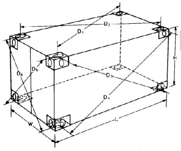
3.1.4 The difference between dimensions D1 and D2, D3 and D4, D5 and D6 measured diagonally across the container from centers of top and bottom apertures on the roof and base, on side walls, on front and rear walls respectively, shown in Fig. 3-1, are not to exceed the permissible variation given in Table 3-2.
Table 3-1
Overall External Dimensions, Permissible Tolerances and Maximum Operating Gross Mass of ISO Series 1 Freight Containers
Container Designation
Length, L, (mm) Width, W, (mm) Height, H, (mm) Max. Operating
Gross Mass, Dimension Tolerances Dimension Tolerances Dimension Tolerances R, (kg)
1A 12,192 0 10 2,438 0 5 2,438 0 5 30,480
1AA 12,192 0 10 2,438 0 5 2,591 0 5 30,480
1AX 12,192 0 10 2,438 0 5 2,438 30,480
1B 9,125 0 10 2,438 0 5 2,438 0 5 30,480
1BB 9,125 0 10 2,438 0 5 2,591 0 5 30,480
1BX 9,125 0 10 2,438 0 5 2,438 30,480
1C 6,058 0 6 2,438 0 5 2,438 0 5 30,480
1CC 6,058 0 6 2,438 0 5 2,591 0 5 30,480
1CX 6,058 0 6 2,438 0 5 2,438 30,480
1D 2,991 0 5 2,438 0 5 2,438 0 5 10,160
1DX 2,991 0 5 2,438 0 5 2,438 10,160
Fig. 3-1 Diagonal Tolerances
Table 3-2 Diagonal Tolerances
ContainerDesignation Maximum Permissible Varations (mm) on Roof and Base D1D2
on Side Walls D3D4
on Front and Rear Walls
D5D6
1A 1AA 19 10
1B 1BB 16 10
1C 1CC 13 10
1D 10 10
3.2 Fittings
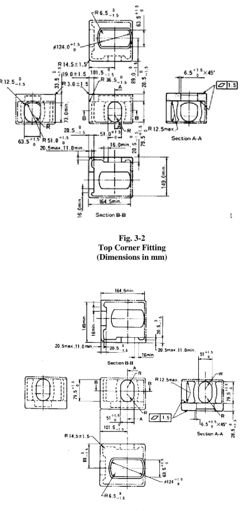
3.2.1 Each container is to be equipped with corner fittings at top and bottom corners. The dimensions and tolerances of corner fittings are to conform to Figs. 3-2 and 3-3. Each container is to have 2 right-hand top corner fittings (on the right as the observer faces the container) and 2 left-hand top corner fittings which are the mirror opposite of the right-hand fittings. For bottom corner fittings, a similar configuration is to exist. Corner fitting drawings illustrate right-hand (RH) top and bottom corner fittings only; for left-hand (LH) corner fittings the dimensions are simply transposed.
3.2.2 Hinges, closing devices and their fittings to the container are to be of suitable material not subject to easy deformation or wear that may impair the safety and tightness of the closure.
3.3 Materials and Workmanship
3.3.1 General(a) Materials used for strength structures of containers are to be in compliance with the appropriate recognized material standard or, if applicable, the requirements given in Part XI of the “Rules for the Construction and Classification of Steel Ships” (hereinafter referred to as “Rules for Steel Ships”). Sufficient information of materials containing manufacturing procedures, grades, mechanical properties, the chemical composition, heat treatments, etc. are to be submitted to the Society for approval.
(b) Structural members of containers are to be of incorrodible materials or subjected to a suitable anticorrosive treatment.
3.3.2 Steels
(a) The choice of the steel type is to be adequate to uses, kinds of structure, thicknesses, bending and to the working and welding requirements. Particular attention is to be paid to working conditions at low temperatures and tanks subject to pressure.
(b) Corner fittings are to be of cast steel or materials with equivalent ductility. Where welding is intended, these are to be of weldable quality.
3.3.3 Aluminium alloys
(a) Alloys are to be incorrodible in marine environments. For this purpose, the copper content is not to exceed 0.05%.
(b) On aluminium alloy plates no altering working is allowed such as direct hammering, heating, surface grinding. Where welding is applied, welded joints are to be capable of maintaining satisfactory properties.
(c) Connections with steel parts are to be carefully worked out, making use of suitable insulation materials.
3.3.4 Timbers
(a) Timbers are to be of good quality, well seasoned, so far as possible free from sapwood, nots, cracks and pits, and in general free from defects that may compromise their soundness and durability.
(b) Plywoods are to be of marine resistant type made up of wood layers treated to protect them against ma rine conditions, and built according to the good practice. Plywood edges are to be protected by glues, varnish or other suitable compositions against moisture penetration and wear.
(c) Wooden surfaces that are not accessible after assembly in place are to be previously coated with linseed oil or other suitable compositions for protection against moisture. Surfaces exposed to contact with water are to be adequately treated, with linseed oil or other substances against rottenness.
3.3.5 Plastics
(a) Reinforced plastics are to be fabricated by competent manufacturer and production procedures are to be recognized by the Society.
(b) The Society has issued particular rules for construction of ships of reinforced plastics, which may constitute a useful guide for fabrication of such material even when intended for use in containers.
(c) The use of rigid expanded plastic materials of prefabricated panels and/or foamed into place for insulation of thermal containers is to be approved by the Society.
3.3.6 Others
(a) The welding for strength structures of containers, containing welding procedures, welder qualifications, operation controls, welding materials, etc., are to be in compliance with the requirements given in Part XII of the Rules for Steel Ships unless otherwise specially approved
Fig. 3-2 Top Corner Fitting (Dimensions in mm)
Fig. 3-3
Bottom Corner Fitting
(Dimensions in mm)
Notes to Fig. 3-2 and 3-3:
1. Solid and dotted lines ( and---) show surfaces and contours which must be physically duplicated in the fitting.
2. Phantom lines ( -- --) show optional walls, which may be used to develop a box-shaped fitting.
3. Outside and inside corner radii where sharp corners are shown must be 3 mm maximum except as noted.
4. Four fittings are required per container: two right-hand and two left-hand.
(b) Glues, caulking materials and gaskets are to be of good marine quality and resistant to maximum and minimum temperatures to be expected in service.
(c) All steel work is to be suitably coated with paint or equivalent coating. Protective coatings on wooden materials are to remain unaltered and such as not to cause damages to the cargo.
3.4 Design Load
3.4.1 The container is to be so designed as to be capable of sustaining the design load specified in Table 3-3.
Table 3-3
Design Load of Containers(1/2)
Items Type of Load Direction of Load Design Load Remarks
Stacking
Concentrated,
eccentrically applied, 38 mm in the longitudinal direction and 25.4 mm in the transverse direction and equally distributed among the 4 corner structures
Vertical downward 1.8superimposed stacking load= 1.8 n Rg
(each corner to take41of design load)
For 1A, 1AA, 1B, 1BB, 1C and 1CC containers, n = 8, R = 24,000 kg.
For 1D containers, n = 5, R = 10,160 kg.
Values for containers of1D are given in brackets
Top lifting Concentrated at pick-up points on 4 top corner fittings
Vertically upward for container 1A, 1AA, 1B, 1BB, 1C and 1CC.
30 to the vertical for container 1D
2R (each corner to take1/4 of design load)
Bottom lifting Concentrated at pick-up points on 4 bottom corner fittings
: Angle to the horizontal
2R (each corner to take 1/4 of design load)
Fork lift pockets
Concentrated at pick-up surfaces of two fork lift pockets
Vertically upward
1.25R (each pocket to take 1/2 of design load)
For 1C, 1CC and 1D containers (when fitted)
Grappler lifting positions
Concentrated at four grappler arm pads
Vertically upwared
1.25R (each grappler position to take1/4 of design load)
When fitted
Table 3-3
Design Load of Containers (2/2)
Items Type of Load Direction of Load Design Load Remarks
Floor loads Concentrated at contact areas of two wheels
Vertically downward
Axle load 54.6 kN, 27.3 kN per wheel.
Wheel width = 180 mm Contact area per wheel
142 cm2
Wheel centers = 760 mm
Side wall
loads Uniformly distributed
Outward normal to sides
0.6 Pg
End wall
loads Uniformly distributed
Outward normal to ends
0.4 Pg
Roof load
Uniformly distributed over an area of 600 mm300 mm located at the weakest area
Downward normal to the roof
3 kN
Longitudinal restraint loads
Concentrated at bottom corner fittings at one end while the other end is secured
Longitudinal compression and tension
2Rg (each side to take 1/2 of design load)
Racking load (longitudinal)
Concentrated at top corner fittings while bottom corner fittings are secured
Longitudinally toward and away from container
75 kN
For 1A, 1AA, 1B, 1C and 1CC containers (1BB)
Chapter 4
Tests and Inspections
4.1 General
4.1.1 Tests and inspection requirements given hereunder are generally applied to general cargo containers, thermal containers and tank containers unless otherwise specified. Requirements for containers of special type, purpose or feature may be modified or specially considered at the prescription of the Society.
4.1.2 Special requirements of tests and inspections for thermal containers and tank containers are additionally specified in 6.5 and 7.5 of the Rules respectively.
4.1.3 Alternative tests and inspection procedures may be accepted if considered to be equivalent to the requirements given in the Rules. The Society may specially consider the requirements for tests and inspections according to other standards when deemed appropriate.
4.1.4 Measuring instruments to be used for tests and inspections are to be calibrated.
4.1.5 On completion of tests, the container is to remain serviceable and is not to show any significant permanent deformation or abnormality which may make it unsuitable for use.
4.2 Inspections of Materials
4.2.1 Materials used in the construction of containers are to comply with the approved design specification of containers.
4.2.2 For materials of strength structures and corner fittings, the manufacturer is to provide the Surveyor with mill sheets containing the information of dimensions, quantity, charge and piece numbers, grades, mechanical properties, chemical compositions, conditions of heat treatment, etc. Testings for such materials at mills may be required to carry out in the presence of the Surveyor as deemed necessary by the Society.
4.2.3 Visual inspections and dimensional checks for each piece of corner fittings are to be carried out in compliance with the requirements of the Rules. Nondestructive examinations and/or compression tests for corner fittings may be required additionally where deemed necessary by the Surveyor.
4.2.4 Strength characteristics of reinforced plastic structures are to be ascertained, where necessary, by means of tensile and impact tests which are to be recognized by the Society.
4.2.5 Insulating materials are to be ascertained subject to successful results of tests made recognized standards.
Tests such as density control, control of contents, self-extinguishing test and vibration test are to be carried out.
4.3 Tests and Inspections for Container Construction
4.3.1 Visual inspections(a) A visual inspection for each container is to be carried out at a proper stage and period during construction and/or after completion. For insulated containers, the visual inspection is to b e conducted prior to commencement of the insulating work.
(b) The construction, material and workmanship of the container are to be ascertained in compliance with the requirements of the Rules without any visual defects in each component of the container.
(c) For containers fitted with doors or other closing appliances, it is to be ascertained that they can be smoothly operated and secured.
4.3.2 Dimensional checks
Each container is to be dimensionally checked after the completion of all the work to ascertain that the container meets the dimensional requirements given in the Rules.
4.3.3 Mass measurement
Mass measurement is to be carried out after the completion of all the works to determine the tare of the container.
4.3.4 Weathertightness tests
(a) A stream of water is to be applied over all exterior surface from a nozzle of 12.5 mm inside diameter, at a pressure of about 0.1 MPa. The nozzle is to be held at a distance of 1.5 m from the part under test with a rate of movement over the exterior of approximately 0.1 m per second. On completion of the test, the container is to be free from penetration of water.
(b) The weathertightness test is to be conducted after all strength tests have been completed. For production units not in need of strength test, the weathertightness test is to be conducted at a reasonable stage during production.
4.3.5 Strength tests
(a) Strength tests are to be carried out as specified in Table 4 - 1 after the completion of all the work.
(b) Measurements are to be taken as required in Table4 -1 before, during and after applying test loads.Additional measurements may be required depending upon the circumstances.
(c) Upon completion of tests, containers are to reveal neither permanent deformation nor abnormality.
4.3.6 Strength tests with one door off operation
(a) Containers with one door removed have a significant reduction in their ability to withstand racking loads and, potentially, a reduction in stacking strength. The removal of a door on a container inoperation is considered a modification of the container. Containers must be approved for one door off operation. Such approval should be based on test results as set forth below.
(b) On successful completion of the stacking test the container may be rated for the allowable superimpo sed stacking mass, which should be indicated on the Safety Approval Plate immediately below line 5:
"ALLOWABLE STACKING LOAD ONE DOOR OFF FOR 1.8g (kg and lb)."
(c) On successful completion of the racking test the racking test load should be indicated on t he Safety Approval Plate immediately below line 6: "TRANSVERSE RACKING TEST FORCE ONE DOOR OFF (newtons)."
Table 4-1
Strength Tests for Containers (1/3)
Tests Test Procedures Measurements
Stacking
Internal loading: 1.8R-T(kg), uniformly distributed over the base.
Applied forces on containers of 1A, 1AA, 1B, 1BB, 1C and 1CC (values for containers of 1D are given in brackets): with the container in the normal position supported at the base corner fittings, comprehensive forces of 847kN (224 kN) to be aplied to each of the four top corner fitting simultaneously, or 1,693kN(448 kN) on each pair of end fittings.
These test forces are derived from thesuperimposed mass of nine-stacking
(six-stacking) i.e. eight (five) containers stacked on top of one container, all being rated 24,000kg (10,160kg) and acceleration force of 1.8g.
The test is to be repeated to cover for all positions of offset, namely 38 mm longitudinally and 25.4 mm laterally.
(i) Deflections at lowest points of bottom side rails and at the longitudinal center line of the base, which may be taken before the application of axial loads.
(ii) Deflections in two directions at midheight, or other point of maximum deflection of corner posts.
(iii) Permanent set remaining on removal of the load.
Top lifting
Internal loading:2R-T (kg), uniformly distributed over the base.
Applied forces: Lifting forces are to be applied gradually to top corner fittings.
(i) Vertically to 1A, 1AA, 1B, 1BB, 1C and 1CC containers.
(ii) At 30C to the vertical in the case of 1D containers.
The container is to be supported for 5 minutes.
(i) While loaded and supported by bottom corner fittings before lifting clear, the deflection at lowest points of bottom side rails and at the longitudinal center line of the base.
(ii) Any distress due to lifting.
(iii) Permanent set remaining on removal of the load.
Bottom lifting
Internal loading: 2R-T (kg), uniformly distributed over the base.
Applied forces: Lifting forces are to be applied gradually through the bottom corner fitting side apertures in direction to the horizontal as follows:
1A, 1AA 30
1B, 1BB 37
1C, 1CC 45
1D 60
The container is to be supported for 5 minutes.
Any distress due to lifting
Lifting from fork lift pockets
Internal loading:1.25R-T (kg), uniformly
distributed over the base. In case the container is fitted with an extra set of fork lift pockets, an additional test is required. A load of 0.625R-T (kg) is to be evenly distributed when lifting from the inner pockets.
Applied forces: The container is to be supported for 5 minutes by two bars, 200 mm wide, inserted to a depth of 1,828 3 mm in each set of fork pockets in turn.
Undue local distortion during the test and any permanent distortion.
Table 4-1
Strength Tests for Containers (2/3)
Tests Test Procedures Measurements
Lifting from grappler arm positions
Internal loading: 1.25R-T (kg), uniformly distributed over the base.
Applied forces: The container is to be supported by four grapler arm positions for 5 minutes. The area of suppport position is to be the same as the grappler arms intended to be used.
Undue local distortion during the test and any permanent distortion.
Floor strength
Internal loading: Nil
Applied forces: A vehicle (wheel centers 760 mm, wheel width 180 mm, maximum contact area per wheel 142 cm2 in the rectangular envelope of 185 mm wide, 100 mm long) loaded to an axle weight of 54.6 kN, 27.3 kN per wheel, is to bemaneuvered over the entire base area.
Deflection and permanent set in three locations of the base.
Side wall strength
Internal loading: 0.6 Pg (N), uniformly distributed over the wall under test.
Application: The container is to be supported in such a manner that the panel is free to deflect over the side wall and its top and bottom side rails.
Unless they are identical, both side walls are to be tested.
Deflection and permanent set at the center of the side wall and the center of the top and bottom side rails.
End wall strength
Internal loading: 0.4 Pg (N), uniformly distributed over the wall under test.
Application: The container is to be supported in such a manner that the panel is free to deflect over its entire surface. Unless they are identical, both end walls are to be tested.
Delfection and permanent set at the center and at least two other locations.
Roof strength
Internal loading: Nil.
Applied forces: 3 kN, uniformly distributed over an area of 600 mm300 mm at the weakest area of the roof.
Maximum deflection and permanent set of the section under test.
Internal loading: R-T (kg), uniformly distributed over the base.
Applied forces: The container is to be secured to
The change in length of both bottom side rails during and after the test in each direction.
Table 4-1
Strength Tests for Containers (3/3)
Tests Test Procedures Measurements
Longitudinal racking
Internal loading: Nil.
Applied forces: The container is to be secured to rigid anchor points through bottom apertures in bottom corner fittings: a longitudinal force of 75 kN is to be applied to top corner fitting(s) on one end. The force is to be applied first toward then away from the container.
Note: Containers 1D need not be tested.
Longitudinal displacement of top side rails is not to exceed 25mm.
Transverse racking
Internal loading: Nil.
Applied forces: The container is to be secured to rigid anchor points through bottom apertures in bottom corner fittings: a transverse force of 150 kN is to be applied to top corner fitting(s) on one side.
The force is to be applied first toward then away from the container.
Note: Containers 1D need not be tested.
Difference in diagonals on one end is not to exceed 60 mm..
Cargo securing system test
Applied forces: The tensile force equal to 1.5 times the rated load is to be continuously applied at the specific angle for 5 minutes as follows:
Sceuring systems
installation Direction of applied forces at the floor
Perpendicularly to the axis of the container structural members 45° to the horizontal plane
above the floor 45° upwards and downwards from horizontal plane at the roof 45° downwards
A minimum rated loading for each anchor point is 10 kN and for each lashing points a minimum rated loading is 5 kN.
Notes:1.Anchor points are securing devices located in the base structure of the container.
2.Lashing points are securing devices located in any part of the container other than the base structure.
Any permanent deformation at cargo securing devices and their attachment to the container structure.
Table 4-2
Strength Tests for Container with One Door Off Operation
Tests Test Procedures Measurements
Stacking
The test procedures should be as set forth under stacking in Table 4-1 except:
Interal loading:
A uniformly distributed such that the combined mass of the container and test load is equal to 1.8R.
Externally applied forces:
Such as to subject each of the four corner fittings to a vertical downward force equal to 0.25 x 1.8 x (the gravitational force of the allowable
superimposed static stacking load.)(newtons)
(i) Deflections at lowest points of bottom side rails and at the longitudinal center line of the base, which may be taken before the application of axial loads.
(ii) Deflections in two directions at midheight, or other point of maximum deflection of corner posts.
(iii) Permanent set remaining on removal of the load.
Transverse racking
The test procedures should be as set forth under transverse racking in Table 4-1 except:
Internal loading:
None.
Externally applied forces:
Such as to rack the end structures of the container sideways. The forces shall be equal to those for which the container was designed.
Difference in diagonals on one end is not to exceed 60 mm..
Chapter 5
General Cargo Containers
5.1 General
5.1.1 The provisions of this section apply to ISO Series 1 general cargo containers defined in 1.of the Rules.
5.1.2 For containers of special types or purposes, requirements are to be specially considered in accordance with the general principles outlined herein.
5.2 Dimensions and Ratings
5.2.1 Dimensions and their tolerances as well as the rating of the container are shown in Table 3-1, Table 3-2 and Fig. 3-1 of the Rules.
5.2.2 Minimum internal dimensions and door opening sizes are shown in Table 5-1.
Table 5-1
Minimum Internal Dimensions and Door Opening Sizes
Container Internal Height Internal width Internal Length Door Opening
Designation (mm) (mm) (mm) Width (mm) Height (mm)
1A 2,197 11,998 2,134
1AA 2,350 11,998 2,261
1B 2,197 8,931 2,134
1BB 2,350 2,330 8,931 2,286 2,261
1C 2,197 5,867 2,134
1CC 2,350 5,867 2,261
1D 2,197 2,802 2,134
5.3 Structural Arrangements
5.3.1 Bases(a) Any bottom structures of a container are not to protrude below corner fittings when the container deflects under a uniformly distributed maximum cargo weight.
(b) ISO containers are to be designed so that no part of base structures is to deflect more than 6 mm below bottom faces of bottom corner fittings under a uniformly distributed load equal to 1.8 R -T.
(c) For containers 1A, 1AA, 1B, 1BB, 1C and 1CC, the height of lower faces of all cross members, including end members are to be 12.5 mm (+5, 1.5) above bottom faces of bottom corner fittings.
5.3.2 Walls
(a) Walls even though provided with openings are to be of sufficient strength to withstand the side wall strength test and end wall strength test described in 4.3.5 of the Rules. Otherwise containers are to be equipped with devices for securing cargo to the base structure so that walls are not stressed.
(b) Open-ends and open-sides containers are to be equipped with devices for securing cargo to the base structure.
(c) For containers 1A, 1AA, 1B, 1BB, 1C and 1CC, the sideways deflection of the top of the container under transverse racking force is not to cause the sum of changes in length of the two diagonals in each end wall to exceed 60 mm.
(d) For containers 1A, 1AA, 1B, 1BB, 1C and 1CC, the longitudinal deflection of the top of the container under longitudinal racking force is not to exceed 25 mm.
5.3.3 Doors
(a) The container is to be provided with an opening at least at one end. The opening is to be as large as possible and preferably equal to the internal cross sectional dimensions of the container. Dimensions of door openings at ends are given in Table 5-1.
(b) Doors are to be provided with substantial securing devices in association with suitable seals to maintain weathertightness under all normal service conditions.
(c) Doors are to be capable of being clasped properly when opened.
5.3.4 Optional Features
(a) Containers 1C, 1CC and 1D may be provided with fork lift pockets. The dimensional requirements are given in Fig. 5-1.
(b) Containers may be provided with features for handling at the base by means of grappler arms or similar devices. The dimensional requirements are given in Fig. 5-2.
(c) Containers 1A and 1AA may be provided with gooseneck tunnels. The dimensional requirements are given in Fig. 5-3.
5.4 Tests and Inspections
5.4.1 Prototype containersThe prototype unit of general cargo container type approval is to be subjected to following tests and inspections:
(a) Visual inspection.
(b) Dimensional check.
(c) Weighing.
(d) Weathertightness test.
(e) Strength tests:
(i) Stackingincluding stacking for container with one door off operation as appropriate.
(ii) Top lifting.
(iii) Bottom lifting.
(iv) Lifting from fork lift pockets (where fitted).
5.4.2 Production units
Production units of approved type series general cargo containers are to be subjected to following tests and inspections:
(a) Visual inspection, dimensional check and weathertightness test for each container.
(b) Weighing for containers of a certain number accepted by the Society.
(c) Strength tests containing stacking, top lifting, bottom lifting and floor strength tests for one container selected at random from each 50 containers or fraction thereof in same series.
5.4.3 Tests and inspections are to comply with the requirements given in Chapter 4 of the Rules.
Dimensions and Tolerances (mm)
Symbols 1C and 1CC
Containers 1D Container
A 2,050 50 900 50
B 355 min. 305 min.
C 115 min. 102 min.
D 20 min. 20 min.
Fig. 5-1
Fork Lift Pocket
Fig. 5-2
Grappler Arm Lifting Positions (Dimensions in mm)
Fig. 5-3
Gooseneck Tunnel
Chapter 6 Thermal Containers
6.1 General
6.1.1 The provisions of this Section apply to ISO Series 1 thermal containers defined in 1.2 of the Rules provided with appliances capable of producing and/or maintaining the temperature conditions inside the containers.
6.1.2 For thermal containers of special types or purposes, requirements are to be specially considered in accordance with the general principles outlined herein.
6.1.3 When thermal containers are intended to be certified, the following plan and data are to be submitted in addition to those prescribed in 2.3.1 of the Rules.
(a) Insulating construction (including material of insulation, data of heat transmission and deta ils of insulating work).
(b) Ventilating devices and drainage.
(c) Specification of refrigerating unit and/or heating equipment (if provided).
(d) Thermometers and temperature recording arrangements.
6.2 Structural Arrangements
6.2.1 GeneralIn addition to the requirements for general cargo container given in 5.3 of the Rules, the following requirements are also to be applied to the thermal container:
(a) Internal dimensions and door openings prescribed in 5.2.2 are not applicable to thermal containers.
However, internal heights and widths and door openings of thermal containers are to be as large as possible.
(b) When containers are provided with ventilation openings, these are to be protected against any possible in-flow of water.
(c) Thermal containers are to be of airtight construction and to comply with the test requirements in 6.5.4 of the Rules.
6.2.2 Insulation
(a) The insulation of the container is to be complete and installed in an effective manner so as to ensure the heat transfer coefficient K and the temperature is maintained within the limits specified in the specifications. The heat transfer coefficient K is generally not to be more than 0.4 W/m2C
(b) Insulation exposed to damage when loading, unloading or cleaning the container is to be suitab ly protected.
(a) The interior surface and structure of the thermal container are to be so constructed as to facilitate cleaning, and adequate provision is to be made to ensure that cleaning water can drain satisfactorily from inside of the container.
(b) Cargo space drains are to be provided with manual closures which are to be airtight and accessible for inspection and easy maintenance.
(c) When a provision of drains in made on the floor of the container such drains are to have a closing device operable from outside the container or an arrangement which is to automatically prevent the entrance of water into the container.
(d) Where operation of cargo space drains is required for thermal containers when carrying cargo, the drains are to be protected by fittings which can open automatically above normal internal operating pressure.
6.2.4 Temperature measuring devices
(a) Suitable instruments are to be provided for measuring the internal temperature of thermal containers. The type, number and arrangement of measuring devices are to be approved by the Society.
(b) The reading scale of the temperature measuring instrument is to cover the whole range involved in operation with a reasonable margin. A suitable device is to be provided for its calibration.
6.2.5 Arrangements for hanging cargo
Where the ceiling of a thermal container is provided with cargo hanging arrangements, the container is to be so designed as to be capable of suspending a load of twice the maximum service load or 30 kN per meter of the usable container length, whichever is the greater.
6.3 Refrigerating Appliances
6.3.1 The capacity of refrigerating unit is to be such as to maintain the inside temperature required by the order specifications in the service conditions, considering the unit to be working over a period of not more than 18 hours a day.
6.3.2 Refrigerating units are also to be capable of efficiently maintaining the specified minimum inside temperature under the test prescribed in 6.5.6 of the Rules.
6.3.3 For appliances requiring water connections inlet and outlet interfaces are to conform to Figs. 6-1 and 6-2.
The water inlet and outlet connections are to be so located at the machinery end of the container that, to an observer facing that end, they appear in the lower right-hand quarter.
6.3.4 For 1AA, 1CC and 1C thermal containers with the design intended for ducted air system or for use with externally located removable equipment, air inlet and outlet openings are to conform to Figs. 6 -3 and 6-4.
6.3.5 The electrical installation is to comply with the relevant requirements in Part VII of the Rules for Steel Ships. A special earthing line is to be connected with the ship earth through the supply attachment.
6.3.6 Devices are to be provided such as to ensure even distribution of cooled air in all parts of the container.
6.4 Materials and Workmanship
In addition to the requirements given in 3.3 of the Rules, the following requirements are also to be applied to thermal containers.
6.4.1 The quality of insulating materials is to be approved by the Society. In particular, they are to be as little hygroscopic as possible, non flame-spreading, odourless and not liable to absorb the odours of the goods carried, proof against breaking up because of shaking, and stable at least in the range of temperature between 30C and +80C.
Pressures Connected Disconnected
MPa MPa
Operating pressure 10.5 2.8
Burst pressure 63 6.3
Fig. 6-1
Cooling Water Connections Inlet Side (Dimensions in mm)
Fig. 6-2
Cooling Water Connections Outlet Side (Dimensions in mm)
6.4.2 When expanded plastic insulating materials are intended to be formed at the site, the method of foaming is to be approved by the Society.
6.4.3 Materials constituting important parts of the refrigerating machinery and appliances are to be of adequate quality and corrosion-resistant.
6.5 Tests and Inspections
6.5.1 Prototype containersPrototype units of thermal container type approval are to be subjected to following tests and inspections.
(a) Items for prototype general cargo containers as required in 5.4 of the Rules.
(b) Roof strength test for hanging cargo (where provided in compliance with 6.5.3 of the Rules.
(c) Airtightness test in compliance with 6.5.4 of the Rules.
(d) Thermal insulation test in compliance with 6.5.5 of the Rules.
(e) Performance test of refrigerating unit compliance with 6.5.6 of the Rules.
6.5.2 Measuring instruments
Measuring instruments used for the tests described in 6.5.4, 6.5.5 and 6.5.6 of the rules are to be properly selected and calibrated to obtain the following accuracy:
Temperature : 0.5C
Power : 2%
Flow : 3%
Pressure : 5%
6.5.3 Roof strength tests for hanging cargo (a) Procedure
A load of twice the maximum service load or 30 kN per meter of the usable container length, whichever is the greater, is to be attached to the roof in a manner simulating normal service loadings, while the container is supported by its base corner fittings only.
(b) Measurements.
Maximum deflection and permanent set of the section under test.
(c) Requirements
On completion of the test, the container is to show neither permanent deformation nor abnormality which may make it unsuitable for use.
Notes:
1. Area about air circulation openings.
(i) Bosses 550 mm diameter or square.
(ii) Face of bosses to be plane to a tolerance of 0.25 mm and smooth.
(iii) Faces of bosses to be parallel to a plane determined by front faces of corner fittings and recessed 3 to 4.8 mm from this plane.
(iv) Holes may have a mould draw taper but no part of the bore of the hole may have a diameter les s than 350 mm.
2. Closures for apertures.
(i) Closure devices that are captive to the container are to be provied for closing off air circulation openings when the container is not connected to a cold air supply.
(ii) Closure devices are to be capable of being sealed.
Fig. 6-3
Air Apertures in End Wall of 1AA Thermal Containers
(Dimensions in mm)
Notes:
1. Area about air circulation openings.
(i) Bosses 457 mm diameter or square.
(ii) Face of bosses to be plane to a tolerance of 0.25 mm and smooth.
(iii) Faces of bosses to be parallel to a plane determined by front faces of corner fittings and recessed 3 to 4.8 mm from this plane.
(iv) Holes may have a mould draw taper but no part of the bore of the hole may have a diameter less than 254 mm.
2. Closures for apertures.
(i) Closure devices that are captive to the container are to be provied for closing off air circulation openings when the container is not connected to a cold air supply.
(ii) Closure devices are to be capable of being sealed.
Fig. 6-4
Air Apertures in End Wall of 1C and 1CC Thermal Containers (Dimensions in mm)
Fig. 6-5
Air Temperature Measurement Points (Inside and Outside)
6.5.4 Airtightness tests(a) Procedure
(i) An airtightness test is to be carried out after the successful completion of a strength test.
(ii) The container is to be in its normal operating condition, and openings and drains are to be closed in the normal manner. The refrigerating unit and/or heating equipment are to be fitted in place, except for the container provided with the removable equipment and having closures at interfaces. In this case, the equipment is to be removed and the closures are to be shut.
(iii) Temperatures inside and outside the container are both to be within the range of 15C to 25C and temperatures are to be stabilized within 3C of each other.
(iv) The air supply through a metering device and a suitable manometer is to be connected to the container by a leak-proof connection. The manometer is not to be fitted direct to the air supply pipe.
(v) The air supply is to be regulated to maintain an
(vi) internal pressure of 250 10 Pa (25 1 mm water head height). After steady test conditions are established, the test pressure is to be maintained for not less than 30 minutes.
(b) Measurements
(i) Inside and outside temperature.
(ii) Air flow required to maintain the test pressure.
(c) Requirements
(i) The air leakage rate, expressed in standard atmospheric conditions is not to exceed following values:
Designation 1A, 1AA 1B, 1BB 1C, 1CC 1D Air leakage rate (m3/h)
30 23 16 9
(ii) For 1C and 1CC containers having air inlet and outlet openings as prescribed in 6.3 of the Rules, tests are carried out with closures shut. The maximum permitted air leakage rate expressed in standard atmospheric conditions is to be 8 m3/h, regardless of the requirement in 6.5.4 (c)(i) above.
6.5.5 Thermal insulation tests (a) Procedure
(i) A thermal insulation test is to be carried out after the successful completion of an airtightness test.
(ii) The test is to be performed with the refrigerating unit and/or heating equipment fitted in place, except that, where the container is designed for use with removable equipment, the equipment is not to be in position but the closures are to be shut.
(iii) The test is to be performed under steady state conditions applying either the internal heating or internal cooling method. For the electrical heating method, a non-radiant heater suitably shielded and circulating fan(s) are to be positioned at the geometric center of the con tainer. No test method used is to result in frost build-up which could affect the test result in any way.
(iv) Temperatures are to be measured at the points shown in Fig. 6-5. All temperature-measuring instruments placed inside and outside the container are to be protected against radiation.
(v) The following conditions are to be satisfied during the test:
The mean wall temperature is to be in the range with a minimum of 20C and maximum of 32C, and the difference between inside and outside temperatures is to be not less than 20C.
The maximum temperature difference between any 2 inside/outside points at any time during the test is to be 3C.
The maximum difference between any 2 average inside/outside air temperatures i/e measured at different times is to be 1.5C.
Maximum difference between lowest and highest power dissipation values is not to exceed 3%
of the lowest figure.
(vi) The test is to be performed for a continuous period of not less than 8 hours and sets of reading are to be recorded at intervals of not more than 30 minutes.
K U S
U Q
S S S
e i
e i
where:
= The mean wall temperature (C).
e = The average outside temperature of the container (C).
i = The average inside temperature of the container (C).
K = The coefficient of heat transfer (W/m2C).
U = The total heat transfer rate (W/C).
S = The mean surface area of the container (m2).
Se = The outside surface area (m2)*.
Si = The inside surface area (m2)*.
Q = The power dissipated or absorbed by the operation of internal heater and fans or internal cooling units (W).
Note: *If areas are corrugated, the projected area is to be used.
(c) Requirements
K value which is obtained from this test is to be not more than 0.4 W/m2C.
6.5.6 Performance tests of refrigerating units (a) Procedure
(i) The container is to be placed in a test chamber where the temperature is held constant at the outside temperature of 38C.
(ii) The container is to be in its normal operating condition but ventilating devices are to be closed.
(iii) The measuring points of temperatures for the outside of the container are to be as prescribed in Fig.
6.5 and for the inside of the container temperatures at the air inlet and outlet are to be recorded at least.
(iv) Using the refrigerating unit, the inside temperature of the container is to be cooled down to the temperature of 18C and maintained for a period of 8 hours.
(v) After completion of the above mentioned test, a non-radiant heater placed in the air stream inside the container is to be turned on, having a capacity of at least 25% of the total heat transfer rate of the container established by the thermal insulation test prescribed in 6.5.5 of the Rules. With the heater in operation the refrigerating unit is to be operated for a period of at least 4 hours.
(vi) The power of the heater, in Watt, is not to be less than that obtained from the following formula:
0.25K S(ei) where:
K = The coefficient of heat transfer established by the thermal insulation test in 6.5.5.
(W/m2C).
S = The mean surface area of the container (m2).
e = Outside temperature of 38C.
i = Inside temperature of 18C.
(b) Measurement
(i) Inside and outside temperatures are to be recorded.
(ii) The power dissipated of electrical heater is to be recorded.
(c) Requirements
It is to be confirmed that the average inside temperature of the container is to be maintained at the specified temperature during the test.
6.5.7 Production units
(a) Production units of approved type series thermal container are to be subjected to following tests and inspections.
(i) Items for production units of general cargo container as required in 5.4 of the Rules except the floor strength test.
(ii) Airtightness test in compliance with 6.5.7 (b) of the Rules.
(iii) Thermal insulation test in compliance with 6.5.5 of the Rules for one container selected at random from each 100 containers or fraction thereof in same series.
(iv) Operation test for refrigerating and/or heating appliances in compliance with 6.5.7 (c) of the Rules.
(b) Airtightness test
An airtightness test in compliance with 6.5.4 of the Rules is generally to be carried out for each container.
If the airtightness test is successfully passed by at least the first 3 containers, a tightness test for the remaining containers may be carried out on one of every 10 containers of the same series using a smoke generator or other equivalent method to determine the location of leaks, which are to be made tight. For this test, the container is to be kept under an internal overpressure of at least 100 Pa (10 mm of water head).
(c) Operation tests for refrigerating and/or heating appliances
The machinery and equipment providing the refrigeration and/or heat functions are to be operated on each containers in order to check that the machinery, controls, air circulating fans and associated equipment are operating satisfactorily.
(d) Test sequences
(i) Sequences for airtightness tests and thermal insulation tests are to comply with the requirements of 6.5.4(a)(i) and 6.5.5(a)(i) in the Rules respectively.
(ii) For production units not in need of strength tests and/or for which the airtightness test is waived in accordance with 6.5.7 (b) above, the airtightness test and/or thermal insulation test are to be carried out at a reasonable stage.
Chapter 7 Tank Containers
7.1 General
7.1.1 The provisions of this Section apply to ISO Series 1 tank containers defined in 1.2 of the Rules.
7.1.2 For containers of special types or purposes, requirements are to be specially considered in accordance with the general principles outlined herein.
7.1.3 For containers intended for carriage of dangerous goods, the design, construction, testing, marking and certification are to be subjected to the additional requirements of the Internal Provisions (IMO) in force.
7.1.4 Tank containers are also to comply with the technical specifications set forth in the documents reacted by the research commission of IMO and of ISO, which may constitute official recommendations.
7.1.5 When tank containers are intended to be certified, the following plan and data are to be submitted in addition to those prescribed in 2.3.1 of the Rules.
(a) Specifications of the tank.
(b) Drawings showing full details of materials, scantlings and welding procedures of the tank.
(c) Arrangement and full details of valves, nozzles and other fittings.
(d) Full details of pressure relief devices.
7.2 Structural Arrangements
7.2.1 General(a) The framework of the tank container is to be designed and constructed in compliance with the requirements for general cargo container except those for structures which are not applicable to the tank container such as walls, doors, fork lift pockets, etc.
(b) Tanks and fittings are to be designed, constructed and tested in accordance with a recognized pressure vessel code and the requirements of this Section.
7.2.2 Each structural member of the container is to be designed taking into consideration the load specified in Table 7-1.
7.2.3 Upper faces of top corner fittings are to protrude above the top of the tank shell and its associated piping and fittings by a minimum of 6 mm.
Table 7-1
Design Load of Tank Container
Items Type of Load Direction of Load Design Load
Stacking Top lifting Bottom lifting
Grappler lifting positions As specified in Table 3.3
Restraint
Longitudinal racking Transverse racking
Longitudinal inertia Uniformly distributed Outwards normal to the end 1P
Transverse inertia Uniformly distributed Outwards normal to the side 1P
Internal pressure Hydrostatically applied in tank or watertight
compartment and associated fittings
1.5 Maximum allowable working
pressure
7.2.4 When the tank container is loaded to R, no part of the tank and its associated shell fittings is to project below a plane 25 mm above bottom faces of lower corner fittings.
7.2.5 The tank container is not to be handled by means of fork lifts, as this method is considered dangerous.
Fork lift pockets are not to be provided.
7.2.6 Walkways where fitted, are to be capable of supporting a load of 3 kN uniformly distributed over an area of 600 mm300 mm.
7.2.7 Ladders where fitted, are to be capable of supporting a load of 2 kN on each rung.
7.3 Tanks and Fittings
7.3.1 Each tank or tanks are to be effectively secured to structural elements of the tank framework and to be capable of being filled and emptied without removal from the tank container.
7.3.2 Tanks or tank compartments without vacuum relief devices are to be designed to withstand an external pressure of at least 0.04 MPa above the internal pressure without permanent deformation.
7.3.6 Pressure relief devices are to have a minimum relief capacity specified in the following table:
ContainerDesignation Minimum Pressure Relief Capacity (m3/min)
1AA 1A 1B 1C 1D
6.4 5.7 4.8 3.8 2.8
7.3.7 Each pressure relief device is to be plainly and permanently marked with the pressure at which it is set to operate.
7.3.8 When a vacuum relief device is required, it is to be designed to prevent permanent deformation of the tank or tank compartments caused by external pressure.
7.3.9 Each tank is to be provided with manholes or other openings of a minimum diameter of 450 mm for inspections, maintenance and repairs.
7.3.10 Gauging devices which may be in direct communication with the contents of the tank are not to be made of glass or of other fragile material.
7.3.11 When insulation is required, the design and construction are to be such that the insulation may in no way interfere with the proper function of the tank fitting.
7.3.12 When heating or refrigeration provisions are required, suitable operational safeguards having regard to the avoidance of the development of excessive temperatures and stresses are to be provided.
7.4 Materials and Workmanship
In addition to the requirements given in 3.3 of the Rules, the following requirements are to be applied to the tank containers.
7.4.1 Materials selected for the tank are not to cause a dangerous reaction when in contact with the contents.
Allowance for corrosion is to be taken into consideration.
7.4.2 Materials are to be suitable for the environmental conditions under which the container is operated. The minimum temperature range over which materials are suitable is to be 10C and 50C.
7.4.3 Welding and preparing works for tanks are to be carried out in accordance with the relevant requirements for pressure vessels, when the tank is defined as a pressure vessel.
7.5 Tests and Inspections
7.5.1 Prototype containersPrototype units of tank container type approval are to be subjected to following tests and inspections:
(a) Visual inspection, dimensional check and weighing in compliance with the requirements given in 4.3 of the Rules.
Table 7-2
Strength Test of Tank Containers
Tests Test Procedures Measurements
Stacking As specified in Table 4.1
Internal loading need not be provided during test.
As specifie din Table 4.1.
Top lifting Bottom lifting
Lifting from grappler arm positions
As specified in Table 4.1 Longitudinal restraint
Longitudinal racking Transverse racking
Longitudinal inertia
Internal loading: R-T, uniformly distributed over the end.
Application: The container is to be positioned with its longitudinal axis vertically and supported by four bottom corner fittings for 5 minutes.
Any distress due to the test is to be recorded
Lateral inertia
Internal loading: R-T, uniformly distributed over the side.
Applicaiton: The container is to be positioned with its transverse axis vertically and supported by four bottom corner fittings for 5 minutes.
Any distress due to the test is to be recorded
(b) Strength tests in compliance with 7.5.2 of the Rules.
(c) Hydrostatic test in compliance with 7.5.3 of the Rules.
(d) Strength test for walkways and ladders in compliance with 7.5.4 of the Rules.
(e) Working test in compliance with 7.5.5 of the Rules.
7.5.2 Strength tests
(a) Strength tests are to be carried out as specified in Table 7-2 after completion of all the works.
(b) The internal loading is to be obtained by filling the tank and a supplementary external loading may be provided, when necessary, in order to achieve the specified loading. The test loading thus applied is to be such as to simulate uniform loading.
(c) The test pressure is to be measured at the top of the tank in its normal position. The test pressure is to be maintained for at least 30 minutes.
(d) Relief devices, where fitted, are to be rendered inoperative or removed.
(e) Where the tank is subdivided into compartments, in addition to the overall test, a h ydrostatic test oneach compartment is to be carried out with contiguous compartments being empty.
(f) During the test, tank boundaries together with associated fittings are to be free from leakage and permanent deformation; container structures are to reveal neither permanent deformation nor any abnormality.
7.5.4 Strength tests for walkways and ladders
(a) A load of 3 kN is to be uniformly distributed over an area of 600 mm300 mm at the weakest section of the walkway.
(b) A load of 2 kN is to be applied on the center of the widest rung of the ladder.
(c) The maximum deflection and permanent set under test are to be measured.
7.5.5 Working tests
On tank containers fitted with pressure relief devices, a working test is to be carried out to ascertain their ef ficiency.
7.5.6 Production units
Production units of approved type series tank container are to be subjected to the following tests and inspections:
(a) Visual inspection and dimensional check in compliance with the requirements given in 4.3 of the Rules f or each container.
(b) Weighing for containers of a certain number accepted by the Society.
(c) Strength tests containing stacking, top lifting and bottom lifting tests in compliance with the requirements given in 4.3 of the Rules for one container selected at random from each 50 containers or fraction thereof in same series.
(d) Hydrostatic tests in compliance with 7.5.3 of the Rules for each container.