Photoinduced two-dimensional gratings based on dye-doped cholesteric
liquid crystal films
Hui-Chen Yeh, Guang-Hao Chen, and Chia-Rong Leea兲
Institute of Electro-Optical Science and Engineering, National Cheng Kung University, Tainan, Taiwan 701, Republic of China
Ting-Shan Mo
Department of Electronic Engineering, Kun Shan University of Technology, Taiwan, Taiwan 710, Republic of China
共Received 23 August 2007; accepted 20 September 2007; published online 12 October 2007兲 This work elucidates photoinduced two-dimensional共2D兲 gratings in dye-doped cholesteric liquid crystal films. The helical pitch is increased by green-beam-induced trans-cis isomerization and a concomitant thermal effect. Two-dimensional gratings appear when the green beam is turned off. Grating formation results from elastic instability caused by restored strain arising from helical pitch reduction. Grating lifetime increases as green beam intensity increases and declines under irradiation with a strong red beam. Variation in grating spacing with green intensity with various pitches is also examined. © 2007 American Institute of Physics.关DOI:10.1063/1.2798103兴
Cholesteric liquid crystals共CLCs兲, which are constricted in a cell with a thickness of d, can be regarded as lamellar phases with a thickness of a layer equal to half of the pitch 共P0兲 at large scales 共dⰇ P0兲.1Two-dimensional共2D兲 gratings
in CLCs fabricated under the application of mechanical tension,2,3an electric field4,5and magnetic field,6,7have been extensively investigated since Helfrich’s pioneering work.8,9 The formation of 2D gratings based on layer undulations in CLCs can be described as follows. The CLC layers are con-fined between two flat plates parallel to the layers. When an external field is applied to the plates, layers tend to reorient. Surface anchoring forces, however, can obstruct free rotation of layers so that the layers undulate with a spatially periodic tilt in the cell plane.
Even though these external forces can induce 2D grat-ings in a CLC system, no work has investigated light-field induction of such gratings. This work studies photoinduced 2D gratings in dye-doped CLC共DDCLC兲 films. The helical pitch of CLCs increases during the irradiation with a green beam due to trans-cis isomerization and a concomitant ther-mal effect. When the green beam is switched off, metastable 2D gratings appear as the CLCs relax. Grating formation based on layer undulations is attributable to the action of the restored strain normal to the layers caused by a drop in the pitch of the CLC structure. Grating lifetime strongly depends on green beam intensity. Variation in grating spacing with green beam intensity with various pitches is also investi-gated. Red-beam-induced cis-trans back isomerization mark-edly reduces grating lifetime.
In this experiment, the nematic LC, chiral dopant, and azo dye are BL009 共n0= 1.5266, ⌬n=0.2915 at 25 °C兲,
CB15, and D2共all from Merck, Germany兲, respectively. Fig-ure1 presents the chemical structures of CB15 and D2共the
chemical structure of BL009 is not available兲. Each empty cell is fabricated from a combination of two indium-tin-oxide 共ITO兲-glass substrates. Homogeneously aligned films of polyvinyl alcohol 共PVA兲 are coated onto the two ITO-glass substrates and rubbed in the same direction. Thickness 共d兲 of each cell is 38m. The DDCLC mixture is injected into empty cells to produce DDCLC cells. Table I lists six DDCLC samples共samples 1–6兲 with different concentrations of chiral dopant from 4.6 to 35.7 wt % of the CLC mixture, where the corresponding pitch 共P0兲 and ratio of d/ P0 are
from 2.87 to 0.38m and from 13 to 100, respectively. The dye dopant concentration in the DDCLC mixture in each cell is fixed at 1 wt %.
The experimental setup for studying the formation of 2D gratings in DDCLC cells is simple. One linearly polarized green beam 共EG兲 from an Ar+ laser 共G= 514.5 nm兲 is
ex-panded and collimated via an expander with a magnification power of 10, and then passes through a diaphragm with an aperture of 0.5 cm in diameter to illuminate normally the
DDCLC cells with a green intensity of IG
= 70– 880 mW/ cm2 for a fixed green pumped duration of tG= 120 s. One very weak 共1 mW/cm2兲 linearly polarized
He–Ne laser beam 共R= 633 nm兲 is utilized to examine the
formation of 2D gratings.
The 2D grating in each sample cannot be formed until the CLCs self-organize for a few seconds after the green
a兲Author to whom correspondence should be addressed. Electronic mail:
[email protected] FIG. 1. Chemical structures of CB15 and D2 used in this experiment. THE JOURNAL OF CHEMICAL PHYSICS 127, 141105共2007兲
0021-9606/2007/127共14兲/141105/4/$23.00 127, 141105-1 © 2007 American Institute of Physics
beam is turned off. Experimental results reveal that the fea-tures of the formed 2D gratings, such as lifetime and grating spacing, depend strongly on the green beam intensity for a fixed green pumped duration. Since the reflection band of the CLCs in sample 6 is in the visible region共curve a in Fig.3兲,
the variation in helical pitch during grating formation can be observed under a polarizing optical microscope 共POM兲. Grating spacing declines during CLC relaxation at IG
⬎200 mW/cm2 but remains constant at I
G艋200 mW/cm2
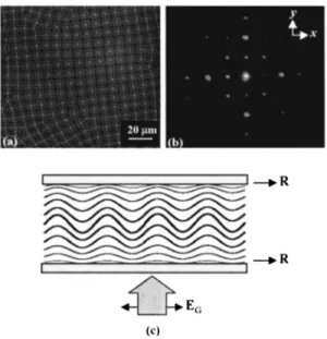
before the grating disappears. Figure2共a兲presents an image of the formed 2D grating obtained with a POM without an analyzer based on sample 6 with IG= 200 mW/ cm2 and tG
= 120 s. Figure 2共b兲 presents the corresponding diffraction pattern of the probe beam from this 2D grating. Spacing of the 2D grating 关Fig. 2共a兲兴 is ⬃9.5m under the POM. Clearly, the diffracted intensity of the second order in the diffraction pattern 关Fig.2共b兲兴 exceeds that of the first order
along the x or y axis, indicating that 2D grating formation is attributable to 2D spatially periodic layer undulations in the CLC structure, in which the grating spacing near the two
substrate surfaces is double that in the cell bulk. Figure2共c兲 presents a model of layer undulations in the 2D gratings, which are similar to those in a pure CLC system to which an electric field is applied.4 Diffraction from the two surface gratings and bulk grating contributes to the mth order and 共2m兲th orders, respectively, of the resultant diffraction pat-tern, where m = 0 , 1 , 2 , . . .. Surface component spacing of the 2D grating is determined from the diffraction pattern using the diffraction condition4
m = ⌳ sin, 共1兲
where m is the diffraction order,⌳ is grating spacing, and is diffraction angle. For the first-order diffraction 共m=1兲 关Fig.2共b兲兴, experimental values =633 nm and = 4.2° are substituted into Eq. 共1兲, yielding a grating spacing ⌳ of ⬃9.6m, which agrees closely with the spacing measured using the POM.
The reflection spectrum of the DDCLC cell共sample 6兲 is obtained to clarify the mechanism of 2D grating formation 关Fig. 2共a兲兴. Figure 3 displays the experimental results. The reflection band of the CLCs is redshifted under illumination with a green beam with IG= 200, 440, and 770 mW/ cm2,
curves b, c, and d in Fig. 3, respectively, for tG= 120 s. The
low transmitted intensity in each curve in the short wave-length region is due to the peak of the absorption of 2D in the green region.10A high green intensity corresponds to a large redshift in the reflection band of the CLCs, suggesting that pitch elongation increases as green beam intensity increases共Fig.3兲. Pitch elongation under green beam
illumi-nation is caused by photoinduced trans-cis isomerization and TABLE I. Six fabricated dye-depoed cholesteric liquid crystal共DDCLC兲 samples with different concentrations
共wt %兲 of chiral dopant in the CLC mixture. The concentration of the dye dopant in the DDCLC mixture in each cell is 1 wt %. Sample number 1 2 3 4 5 6 Chiral dopant in CLC mixture 共wt %兲 4.60 9.4 11.3 14.6 29.5 35.7 P0共m兲 2.87 1.44 1.20 0.93 0.45 0.38 d / P0 13 26 32 41 85 100
FIG. 2. 共a兲 A formed two-dimensional 共2D兲 grating under a polarizing op-tical microscope共POM兲 without an analyzer based on dye-doped cholesteric liquid crystal 共DDCLC兲 cell with P0= 0.38m 共sample 6兲 for IG
= 200 mW/ cm2and t
G= 120 s. Grating spacing is⬃9.5m under the POM.
共b兲 Corresponding 2D diffraction pattern and 共c兲 model of undulations of layers in the 2D grating, in which EG and R represent the polarization
direction of the linearly polarized green beam and the rubbing direction of the cell, respectively.
FIG. 3. Curves of the reflection spectrum of CLCs for sample 6 in dark 共curve a兲 and under green beam illumination with IG= 200, 440, and
770 mW/ cm2共curves b, c, and d, respectively兲 for t
G= 120 s.
141105-2 Yeh et al. J. Chem. Phys. 127, 141105共2007兲
the concomitant thermal effect.11,12 The increase in cis-isomer concentration and temperature with green beam in-tensity, therefore, increases pitch elongation. After the green beam is turned off, the cis isomers may be thermally back
cis-trans isomerized to the original trans isomers13 and cell temperature returns to room temperature 共TR兲 via thermal
relaxation, recovering CLC pitch.11,12As is known, the elas-tic energy of a CLC system is associated with helical pitch.14 Elastic energy is enhanced when pitch is elongated. The drop in pitch causes elastic energy to be released and, in turn, a restored strain in the normal direction to the cell substrates can be induced, producing elastic instability under confined surface alignment, thereby resulting in the metastable 2D grating. After the cis isomers have all thermally isomerized back to the trans state and temperature has decreased back to
TR, CLC pitch no longer varies and strain is zero, resulting in
the disappearance of the grating. The mechanism of forma-tion of 2D gratings is also supported by the investigaforma-tion by Clark and Meyer,2which indicated that elastic instability in CLCs was produced by purely decreasing temperature of CLC cells without green beam irradiation.
To clarify the influence of the concomitant thermal effect on formation of 2D gratings, a separate experiment with two steps is performed. First, a thermocouple is used to measure the DDCLC cell共sample 6兲 temperature at the pumped spot after illumination with the green beam for 120 s. Tempera-ture increases from 25 共room temperature兲 to 29, 32.5, and 37 ° C when green beam intensities are 200, 440, and 770 mW/ cm2, respectively. Second, the cell is then placed in
a hot stage, in which cell temperature is set at 29, 32.5, and 37 ° C. Figure 4 displays cell reflection spectrums at these temperatures. Experimental results show that the redshift of the reflection band clearly increases when temperature in-creases from 25 to 29, 32.5, and 37 ° C, as demonstrated by curves of b, c, and d共Fig.4兲. Therefore, the influence of the
concomitant thermal effect on pitch and, thus, on formation of 2D gratings is significant.
Figure5共a兲关Fig.5共b兲兴 presents the variation in 2D grat-ing lifetime with green beam intensity for tG= 120 s without
共with兲 irradiation by the pumped red beam with intensity IR
= 500 mW/ cm2, after the green beam has been turned off.
The lifetime of the 2D grating increases as green beam in-tensity increases关Fig.5共a兲兴. The experimental results can be explained as follows. The concentration of cis isomers pro-duced by photoisomerization and the concomitant thermal
effect can both increase as green beam intensity increases, thereby increasing pitch. Accordingly, the time that the pitch and temperature take to recover to their original values in-creases once the green beam is turned off, yielding the ex-perimental results 关Fig.5共a兲兴. Figure5共b兲 shows a tendency similar to that in Fig.5共a兲; however, lifetime declines under irradiation from the pumped red beam after the green beam is turned off. The strong red beam can rapidly induce the trans-formation of cis isomers to trans isomers13 and, in turn, ac-celerate the pitch recovery to its original value, causing grat-ing lifetime to decline.
Figure6共a兲plots the spacing variation of the formed 2D gratings with green beam intensity at IG艋200 mW/cm2 for
tG= 120 s in samples 2–6. The increase in grating spacing
with increasing green beam intensity increases as CLC pitch in these cells declines. This experimental finding is because a short CLC pitch corresponds to increased sensitivity of the pitch to photoinduced trans-cis isomerization. Grating spac-ing of CLCs with a short pitch is, therefore, sensitive to variation in green beam intensity. When the pitch is suffi-ciently long—say, 1.20 or 1.44m—the sensitivity of pitch elongation and grating spacing to green beam intensity de-creases. When P0 exceeds 2.87m 共sample 1兲, such that d / P0is⬍13, the variation in pitch is eliminated and no 2D
grating appears, regardless of green beam intensity.
In summary, this work demonstrated photoinduced 2D gratings on DDCLC films under green beam illumination. The helical pitch of the DDCLC films is increased by
trans-cis isomerization of azo dyes and the concomitant thermal
effect during green beam irradiation. When the green beam is FIG. 4. Curves of the reflection spectrum of CLCs for sample 6 at 25, 29,
32.5, and 37 ° C共curves a, b, c, and d, respectively兲 without green beam illumination.
FIG. 5. Lifetime variation of 2D grating with green beam intensity based on sample 6共a兲 without and 共b兲 with irradiation of a pumped red beam with an intensity of 500 mW/ cm2after the green beam is turned off.
FIG. 6. Spacing variation of 2D grating with green beam intensity in DDCLC cells with various helical pitches.
141105-3 Photoinduced gratings in crystal films J. Chem. Phys. 127, 141105共2007兲
turned off, 2D gratings appear as the CLC structure relaxes. Both thermal cis-trans back isomerization and thermal relax-ation induce recovery of the CLC pitch. The mechanism of formation of gratings is attributable to the elastic instability arising from restored strain established by pitch recovery. Irradiation with one strong red beam on the formed 2D grat-ings in DDCLC cells can generate photoinduced cis-trans back isomerization, thereby reducing significantly the grating lifetime. Additionally, grating spacing is sensitive to the green beam intensity only for CLC cells with short pitches.
The authors would like to thank the National Science Council of the Republic of China, Taiwan, for financially supporting this research under Contract No. NSC 95-2112-M-006-020-MY2. Ted Knoy is appreciated for his editorial assistance.
1M. Kleman and O. D. Lavrentovich, Soft Matter: An Introduction 共Springer, New York, 2003兲, p. 405.
2N. A. Clark and R. B. Meyer, Appl. Phys. Lett. 22, 493共1973兲. 3M. Delaye, R. Ribotta, and G. Durand, Phys. Lett. 44A, 139共1973兲. 4B. I. Senyuk, I. I. Smalyukh, and O. D. Lavrentovich, Opt. Lett. 30, 349
共2005兲.
5S.-W. Kang and L.-C. Chien, Appl. Phys. Lett. 90, 221110共2007兲. 6J. P. Hurault, J. Chem. Phys. 59, 2068共1973兲.
7T. Ishikawa and O. D. Lavrentovich, Phys. Rev. E 63, 030501共2001兲. 8W. Helfrich, Appl. Phys. Lett. 17, 531共1970兲.
9W. Helfrich, J. Chem. Phys. 55, 839共1971兲.
10H.-C. Yeh, G.-H. Chen, C.-R. Lee, and T.-S. Mo, Appl. Phys. Lett. 90, 261103共2007兲.
11Y. Yu and T. Ikeda, J. Photochem. Photobiol. C 5, 247共2004兲. 12H.-K. Lee, K. Doi, H. Harada, O. Tsutsumi, A. Kanazawa, T. Shiono, and
T. Ikeda, J. Phys. Chem. B 104, 7023共2000兲.
13J. F. Rabek, Photochemistry and Photophysics共CRC, Boca Roton, FL, 1990兲, p. 120.
14L. M. Blinov, Electro-Optical and Magneto-Optical Properties of Liquid Crystals共Wiley, Chichester, 1983兲, p. 225.
141105-4 Yeh et al. J. Chem. Phys. 127, 141105共2007兲