行政院國家科學委員會專題研究計畫成果報告
計畫編號:NSC 89-2416-H-009-036
執行期限:89 年 8 月 1 日至 90 年 7 月 31 日
主持人:楊 千 國立交通大學經營管理研究所
一、中文摘要
電子商務時代的到來,使得企業經營
運作之各項資訊與企業網路有著密不可分
的關係,企業網路的運作績效影響著企業
整體的經營績效;如何有效運用企業網路
的資源與頻寬,為企業提昇競爭力的重要
關鍵,本研究提出企業網路差別性服務機
制,藉由企業網路流量分類機制,針對傳
輸資料的特性,予以區分成:促進式轉送
網路資料流、保證式轉送網路資料流與預
設值轉送網路資料流等三個等級,應用於
所提出的差別性服務機制中,利用資料傳
輸優先權的比較,將不同種類的資料流量
配置不同的網路資源與頻寬,使具有優先
傳送權的流量能夠被優先傳送,而不具優
先傳送權的流量將被延遲傳送,藉以提供
企業網路的差別性服務,期能與企業網路
的整體運作結合,提昇企業網路運作效
能,增強企業營運的競爭力。
關鍵詞:差別性服務、促進式轉送資料
流、保證式轉送資料流、盡力式
轉送資料流、傳輸優先權。
Abstract
E-commerce makes a relationship
closer between enterprises’ operation
information and enterprise network. A
network performance of an enterprise will
impact its operation performance. How to
efficiently utilize an enterprise network
resources and its bandwidth? It is an
important issue for an enterprise to enhance
its competition capability in an E-business
era. This research proposes a differentiated
service mechanism to manage traffic flows
in an enterprise. With this mechanism,
enterprise network traffic flows are divided
into three categories by their characteristic:
expedited forwarding flow, assured
forwarding flow and best effort flow. Basing
on these three flows, differentiated services
would be provided in an enterprise network.
According to their importance and urgency
of enterprise flows, higher priority flows
receive more bandwidth and better
performance and lower priority flows would
be delayed to release bandwidth. This
mechanism would enhance the performance
of an enterprise network and help an
enterprise get the urgent and important
operation information as soon as possible.
With a high performance enterprise network,
an enterprise would operate more efficiently
and improve its competition capability.
Keywords: differentiated service, expedited
forwarding (EF), assured
forwarding (AF), best-effort
(BE), priority
二、緣由與目的
企 業 網 路 隨 著 電 腦 網 路 技 術 的 演
進,其所提供的功能與服務漸趨完備,企
業經營運作之各項資訊與企業網路有著密
不可分的關係。然而,隨著企業組織的日
漸成長,各項業務量大增,各種的網路應
用亦隨之大量的增加。企業網路為擔負企
業內部電腦資訊傳輸的骨幹,但其傳輸頻
寬有限,無法無限制地滿足企業組織成長
的所有資訊傳輸需求,造成既有的企業網
路無法適時滿足企業的作業需求,如何提
升企業網路的運作績效,支援企業資訊管
理系統的運作與企業營運所需,為大多數
企業所面臨的問題。此外,電子商務時代
的到來,無論在企業間(B2B)的商務往來或
是 企 業 與 消 費 者 間 (B2C) 的 銷 售 購 物 行
為,均需要一個完善的網路系統做為基礎
架構,以快速地支援相關的電子商務行為
的運作,滿足客戶的需求;這亦驅使企業
需要一個快速、能夠有效支援電子商務運
作的企業網路。所以,企業網路運作績效
的良窳欲否影響著企業的整體營運成效,
如何發揮企業網路的最大效能,為業界所
共同面臨的一大問題,亟待解決之。
企業網路所傳輸之資料來自於企業
的內外,其所涵蓋的內容包羅萬象,從緊
急重要的經營資訊到毫無用處的垃圾郵
件,無論所傳送的資料為何,都需要佔用
珍貴企業網路的頻寬,企業如沒有對企業
網路所傳送的資料予以適當的管制,很容
易形成網路資料流量的氾濫,造成企業網
路的擁塞,無法適時地提供企業整體運作
所需。故適切的資料流量管制措施,對企
業網路系統的運作是有其必要性:適當地
分配與應用企業網路資源,利用企業網路
的差別性服務的觀念,對企業重要或是具
有時間急迫性的營運資訊提供一定的網路
品質服務(QoS),使其能夠在時限內正確
地傳送給接收者,適時地發揮該項資訊的
功效,將有助於企業網路績效的提昇,滿
足企業營運的需求。
企業網路差別性服務係指:企業營運
過程中所產生的各項電腦資訊,應依其內
容、性質、傳送部門或接收部門、重要性
與迫切性,在傳輸時效上做不同程度的區
分,予以不同的傳送權限,傳送權限高的
訊息優先傳送,傳送權限低的訊息則暫緩
傳送,如此企業網路方能有足夠的頻寬,
迅速地將企業的重要訊息在時效內傳達,
滿足營運需求。
本 研 究 將 嘗 試 就 企 業 網 路 資 料 流
量,提出一個分類機制:針對傳輸資料特
性,予以分類:促進式轉送網路資料流、
保證式轉送網路資料流與預設值轉送網路
資料流等三個等級,企業網路將以此三種
經分類的資料流量為基礎,應用於新提出
的差別性服務機制中,針對不同種類的資
料流量配置不同的網路資源與頻寬,使具
有優先傳送等級的資料流量能夠被優先傳
送,而不具優先傳送等級的資料流量將被
延遲傳送,以提供企業網路的差別性服
務,期能結合企業網路的整體運作,提昇
其效能,增強企業營運的競爭力。
電子商務的興起,造成企業網路出現
擁塞現象,降低企業網路運作效能,進而
迫使企業整體的營運績效為之趨緩;根據
美國 Zona Research 公司西元 1999 年的研
究資料指出:由於網路傳輸績效不彰,將
造成產業界每月損失 362 百萬美金的營
收;同時,根據該公司另一份有關於網路
族群上網行為與網站回應時間研究數據顯
示:損失 10%到 30%可預期消費群的網站回
應時間長短,往往只有一秒鐘的時間差
別,網站回應時間些許的遲緩,將造成一
定數量客戶的流失,商機因此稍縱即逝;
該份研究資料亦指出:網站回應的關鍵時
間是7秒鐘,若網路回應時間少於7秒
鐘,上網族離開該網站的機率小於 10%;
若網路回應時間多於7秒鐘,上網族離開
該網站的機率呈現快速上升的狀態,尤其
是網路回應時間在7∼8秒之間,上網族
離開該網站機率上升的速度最快,由 10%
急遽上升至 30%,網路回應時間超過8秒
鐘之後,上網族離開該網站機率從 30%的
持續向上攀升,但攀升的幅度較7∼8秒
間離開機率的攀升為平緩。所以,從該份
研究資料中,可以瞭解企業採行電子商務
為其營運模式,必須具備高效能的企業網
路,能夠快速地回應與服務客戶,滿足其
需求,方能適時地掌握網路商機,為企業
獲取應有的利潤。所以,如何解決企業網
路擁塞現象,提升應有的傳輸績效,維持
一定的網路回應時間與服務品質,實為當
今企業經營電子商務所需面臨亟需解決的
當務之急。
三、結果與討論
本研究在探究差別式服務的擁塞控
制機制對於企業網路資料傳輸績效之提
昇,以支援企業營運之所需,強化其競爭
力。
企業往往因所涉略產業、營運方式與
經營規模的不同,影響其內部的組織架構
與其運作方式,故不同企業的營運資訊亦
不盡相同,影響著企業網路資訊的傳輸與
運用情形。雖然企業網路的運作因企業本
身的特性有所差異,但都共同的特點發
生:網路頻寬的使用出現失調現象,頻寬
的尖峰使用相當集中於部分時段,且遠遠
超出企業網路本身所能提供的頻寬使用
量,但就網路頻寬長期平均的使用量而
言,企業網路頻寬所提供資料傳輸能量顯
然足夠應付企業所需。
「流量差別性服務」係指在不另行投
入經費提昇企業網路架構與頻寬的前提
下,利用現有的網路資源與頻寬,將企業
組織運作下所產生各項所需網路傳輸的資
訊,針對所產生資訊的內容、性質、重要
性與迫切性等相關因素,加以分類,分別
賦予不同的網路傳送優先等級,在網路傳
輸上,予以適切地管制規範,讓影響企業
運作的最重要資訊能夠在企業網路上最優
先被傳送,以發揮該項資訊最大的時效
性。此一「流量差別性服務」措施將使企
業能夠以最少的投資,讓企業網路發揮最
大的效用,對企業組織而言,是一個經濟
實惠的可行方案。
企業網路流量分類機制是企業網路
差別性服務機制運作的基礎,企業網路內
所有的資料流量均需透過此一機制加以過
濾篩選,依據資料流量相關的特性與企業
營運的需求,分別賦予其不同的資料類
別;企業網路差別性服務機制則依據企業
網路流量分類機制的分類結果,對於不同
類別的資料流量分別配置不同的企業網路
資源與頻寬,提供差別性的網路傳送服
務。企業網路流量分類機制的主要功能在
於如何將企業網路資訊予以分類,其分類
標準往往會因企業組織結構與營運特性的
不同,而有差異;但大體而言,有著一些
脈絡可供遵循,概略地可區分成下列幾
類:訊發送
接收人的管理位階、個部門
經管的業務特性、時間因素、資訊應用系
統的特性、突發性特殊事件或其他因素。
企業網路流量差別性服務機制即是
將電腦網路流量差別性服務的觀念應用於
企業網路運作之中,期使企業網路流量能
依據企業網路流量分類機制所產生的等級
分類結果,做為提供企業網路差別性服務
功能的依據,不同等級的資料流量可獲得
多少不等的企業網路頻寬配置,而提供不
同傳送速度的網路服務,進而使企業網路
的整體運作能夠儘量滿足企業整體營運之
需求。
電腦網路差別性服務機制是由 IETF
差 別 性 服 務 工 作 群 組 ( Differentiated
Service Working Group)所提出的一套網
路差別性資料傳輸處理機制[10],它能夠
將網路資料流量區分成數個不同的服務等
級,不同的服務等級將可獲得不同網路資
源與頻寬的配置,而達到網路資料傳輸差
別性服務的目的。電腦網路差別性服務機
制(DiffServ)會將封包分類為不同等級的
單一跳躍轉送行為(Per-Hop Forwarding
Behavior, PHB)[10],單一跳躍轉送行為
是一種網路轉送資料封包行為的特性描
述,為具有相同差別性服務特性的資料流
封包集合。目前所提出的單一跳躍轉送行
為 可 區 分 成 三 種 : 盡 力 式 轉 送
(Best-Effort Forwarding, BE)、促進
式轉送(Expedited Forwarding, EF)與
保證式轉送(Assured Forwarding, AF)。
多 重 通 信 協 定 標 籤 交 換 機 制
( Multiprotocol Label Switching,
MPLS)[2]係藉由特定網路區域的標籤交換
運作與網路第二層高速資料訊框轉送能力
結合,大幅地減輕網路路由器的處理負擔
與資料路徑選擇的擁塞現象,使得資料封
包得以快速地傳送至目的地,可大幅提昇
企業網路資料傳輸的效能。所以,在本研
究將多重通信協定標籤交換機制應用於企
業網路流量差別性服務機制之中,期望藉
由多重通信協定標籤交換機制的特性與高
效率的資料傳輸功能,加速企業網路的資
料傳輸效能與強化企業網路流量差別性服
務機制的功效。
MPLS 網域 核心路由器 核心路由器 核心路由器 EF 資料流標籤交換路徑 AF & BE 資料流標籤交換路徑 邊緣路由器 EF 資料流 AF 資料流 BE 資料流 邊緣路由器 邊緣路由器 邊緣路由器應用多重通信協定標籤交換機制網
路來支援企業網路差別性服務機制,我們
可以利用每一個資料流所建立的標籤交換
路徑所賦予不同的特性,並將這些特性與
企業網路流量分類機制所產生的分類結果
相互結合,以便能夠分別符合企業網路差
別性服務機制對網路資料流量的不同要
求。因此,將產生三種類別的網路資料流
量:促進式轉送、保證式轉送與盡力式轉
送。它們對企業網路資源與頻寬的需求各
有不同的特點:
促進式轉送資料流:
相當於促進式單一跳躍轉送行為,對於
企業網路頻寬的需求不一定最多,但是
資料傳輸時效的要求最為嚴格:保證隨
時取得所需網路頻寬,不允許網路延遲
時 間 的 變 化 量 過 大 , 且 不 允 許 掠 奪
(preemption)該預留的網路頻寬,使
用上可能為需要即時反應的網路應用,
如:聲音在網際網路上的傳輸(Voice
over IP, VoIP)、視訊會議與企業內需
要及時處理的重要網路資訊,如:具有
時效性的決策階層資訊或是會議訊息
等。
保證式轉送資料流:
相當於保證式單一跳躍轉送行為,企業
網路將提供最少的網路資料傳輸頻寬保
證,如有多出最小限度的頻寬則可加以
利用。在此一類型的網路傳輸模式中,
掠奪網路頻寬的情形會因資料流傳輸的
優先等級不同而可能發生,傳輸優先順
序高的資料流可以掠奪傳輸優先順序較
低資料流的網路頻寬。在企業網路中,
保證式轉送網路資料流將能夠提供企業
重要的網路資料一定的網路傳輸品質保
證,使重要的企業營運資訊如:重要客
戶訂單、公司重要營運資訊等,能夠在
一定的時間範圍內正確地傳送至接收
端。
盡力式轉送資料流:
相當於盡力式單一跳躍轉送行為,它的
網路傳輸優先等級最低,當企業網路頻
寬還有可供傳輸資料時,盡力式轉送資
料流方能進行資料的傳輸,此外,當其
他二類型網路資料流頻寬不充足的時
候,便成為最先被掠奪的對象,它無法
提供網路服務品質的保證。盡力式轉送
網路資料流往往為對時效性要求很低的
工作,如:企業中不具時效性的批次處
理工作、企業網路資料備份等或是企業
員工私人的網路資訊處理工作等。
關於路徑選擇是屬於服務品質路徑
選擇的問題,本研究依據連線掠奪路徑選
擇演算法為基礎,提出了一個以經過路徑
上最小的資料傳輸優先權總合(Min_Pri)
演算法做為企業網路差別性服務機制掠奪
傳輸路徑選擇的依據。
Min_Pri 演算法:步驟一、建立記錄可使用的網路之樹狀結構
針對所有網路資料流量,利用紀錄它們 進入企業網路的進入節點、資料接收端 點與多重通信協定標籤交換機制所建立 的標籤交換路徑等相關資,瞭解所有可 能使用的資料傳輸線路並逐一檢查,建 立可使用路徑集合,同時以樹狀的資料 形態加以建置。步驟二、針對需求篩選出可使用的路徑
對於進入企業網路資料流有服務品質 的特殊需求,如:網路頻寬或資料傳輸 延滯時間等,將依據其網路服務品質的 要求,濾過並搜尋所有可能的傳輸路 徑,篩選出適當的傳輸路徑,以供該網 路資料流使用,滿足網路服務品質之要 求。步驟三、單一連結線路的最小優先權總合
單一連結線路係指二個路由器、交換器 或是相關網路連結設備間的企業網路 線路。在單一連結上數個可供掠奪頻寬 的傳輸路徑中,其選擇法則為:優先選 取優先權最小的傳輸路徑,如所需企業 網路頻寬不足時,則再選優先權次小的 傳輸路徑,依此類推,增加所需之網路 頻寬,直到已選擇頻寬總合大於或等於 所需之企業網路頻寬為止。步驟四、整條傳輸路徑的最小優先權總合
整條傳輸路徑係指資料流進入企業網 路的進入節點到接收節點間所經過各 個單一連結線路的集合。在選擇整條傳 輸路徑的最小優先權總合時,則是將可 供選擇最小優先權之單一連結線路分 別列出,即先前所建立之樹狀資料形 態,透過此一樹狀資料形態,找出所要 掠奪的連結之優先權總合為最小者。Min_Pri 演算法運算原理與構想是依
據資料流傳輸優先權限高低不同所找出的
可掠奪網路傳輸路徑,當可掠奪的情形發
生時,被掠奪的路徑將被迫重新選擇一條
路徑,同樣的,它也必須在頻寬不足時去
掠取其他路徑的頻寬,如此周而復始,這
樣就像是骨牌效應一般的副作用,很明顯
的會影響到整個網路的效能,所以,在找
尋最佳的傳輸路徑且有掠奪行為要發生
時,將儘可能的選擇有最小的頻寬、最少
的掠取路徑數目及最低的傳輸優先權限。
最小的頻寬可以使網路的頻寬使用率提升
至最高,而最少的掠取路徑數目與最低的
傳輸優先權限均可使掠奪行為發生時所造
成副作用影響降到最小。從 Min_Pri 演算
法運作過程中可以發現網路的整體企業網
路頻寬使用率的提高顯然必需要犧牲某些
資料流量的網路服務品質,因為每個資料
流量連結的頻寬使用狀況和延遲時間並不
相同,對整體企業網路而言,掠奪最小傳
輸優先權的標籤交換路徑頻寬,可以將這
種一條或數條路徑重新選擇的副作用減至
最小,因為被選擇路徑優先權低,大多是
不會在重新選擇傳輸路徑時造成影響。
本研究使用美國勞倫斯國家實驗室
與加州柏克萊大學所合作發展的網路模擬
器 ns-2[11],做為本研究所提出企業網路
流量差別性服務機制的模擬載台與實驗環
境。差別性服務機制模擬想定將簡化企業
網路架構,分別就單一標籤交換路徑與多
重標籤交換路徑之差別性服務進行模擬並
分析該機制之運作結果。
一、單一標籤交換路徑上差別性服務機制
之模擬
為了模擬企業網路流量差別性服務
機制的運作情形,觀察在網路擁塞的情況
下三種不同類別的交通狀況,在模擬的實
驗設計上,我們設定了一個簡單化的網路
環境,用以模擬部分企業網路環境的運作
情形,其網路拓樸如上圖所示。
在這個模擬想定中,將依據企業網
路資料流三種不同轉送需求的運作特性,
分別設定不同的傳輸特性,如:1.在促進
式轉送網路資料流等級中,在其所配置的
網路頻寬限額內的資料傳輸速率是被保證
的,但是一旦資料傳輸速率超過保證頻寬
時,多餘的資料量將會無法傳送至目的
地。2.在保證式轉送網路資料流等級中,
除了保證的配置一定比例網路頻寬外,當
網路連結線路上有多餘可供利用的頻寬
時,企業網路流量差別性服務機制會依照
各個相關保證式轉送網路資料流優先權的
高低再加以分配。
由單一標籤交換路徑的模擬結果與分
析,我們可以得到下面的結論:
(一)在配置足夠網路頻寬給 EF 資料
流,EF 資料流將可獲得最大值傳輸
需求的滿足。
(二)AF 資料流將可獲得預設的最小頻
寬配置;在滿足 EF 資料流頻寬需
求與 AF 資料流的最小頻寬後,若
有多餘的頻寬可供使用,則依優先
權的高低可分別獲得額外得頻寬配
置,以滿足其傳輸需求。
(三)在滿足其他類資料流的頻寬需求
後,仍有頻寬可供使用,BE 的資
料流才能得到頻寬的使用權。
二、多重標籤交換路徑上差別性服務機制
之模擬
EF1 EF2 AF1 AF2 AF3 BE1 路由器1 路由器2 1Mbps 20ms 1Mbps 1Mbps 1Mbps 1Mbps 1Mbps 1Mbps 路由器4 路由器3 2Mbps 10ms 1Mbps 5ms 2Mbps 10ms 1Mbps 5ms EF1 EF2 AF1 AF2 AF3 BE1 邊緣路由器 核心路由器 4Mbps 1Mbps 1Mbps 1Mbps 1Mbps 1Mbps1Mbps R1 R2在多重標籤交換路徑上,我們依據網
路流量工程常用的模擬分析之網狀邏輯網
路 拓 樸 (Mesh Logical Network
Topology),進行差別性服務機制之模擬,
模擬中各個不同類級與優先權資料流的資
料傳輸行為模式和路徑的選擇方式,檢視
其能否滿足企業網路差別性服務機制的功
能與網路服務品質的要求。
依據模擬結果分析,我們發現下列的
幾點觀點:
(一)F1 資 料 流 因 其 對 延 遲 時 間 的 限
制,只能選擇 1-4-2 這條路徑來遞
送資料。
(二)AF1 資 料 流 因 其 對 頻 寬 的 限 制
(2Mbps > 1.2Mbps > 1Mbps),雖
然實際所使用的頻寬只有 1Mbps,
但對於 AF 必須滿足其最小要求,
只能選擇 1-3-2 這條標籤交換路徑
來傳送資料。
(三)BE1 資料流當頻寬充足時,可隨意
使用頻寬,但當頻寬不足時,所使
用的頻寬會被優先權高的資料流掠
奪,被迫選擇其他路徑繼續資料的
傳送,如此將使得 BE1 資料流的傳
輸效能低落。
(四)AF2 資料流只能選擇仍有可用頻寬
1.0Mbps 的路徑 1-3-2 來使用。
(五)EF2 資料流在最小優先權頻寬掠奪
的考量下:1-3-2 標籤交換路徑已被
AF1 與 AF2 資料流使用,1-2 標籤
交換路徑為 BE1 資料流所使用,
EF2 資料流選擇掠奪在 1-2 標籤交
換路徑上 BE1 資料流的頻寬。如果
是選擇 1-3-2 這條標籤交換路徑,
則 AF2 資料流將會因可用頻寬不
足而被迫再選擇到 1-2 標籤交換路
徑上與 BE1 資料流競爭頻寬的使
用。
(六)AF3 資料流因為優先權低,只能選
擇仍有 0.6Mbps 頻寬可使用的 1-2
標籤交換路徑,同時掠奪 BE1 資料
流所使用之頻寬。
由上述的探討說明與模擬結果可以
瞭解:在企業網路中經由多重標籤交換路
徑的應用,支援企業網路差別性服務機制
的運作,可以確實達到對企業內網路資料
流品質服務的控制,提升企業網路整體運
作的效能。
四、計畫成果自評
本計畫研究主題為「企業網路差別性
服務機制之研究」,主要針對企業網路資
料流量傳輸可能遭遇的瓶頸嘗試進行瞭解
與研究。
企業網路效能的提昇為企業營運所
面臨的重要問題之一,企業網路流量差別
性服務機制將可以提供一套網路運作機
制,解決企業網路頻寬不足的問題。企業
網路流量差別性服務機制針對企業網路上
的資料流特性,在企業網路上提供差別性
服務,它將企業網路資料流量區分成三種
資料流:促進式轉送網路資料流、保證式
轉送網路資料流與預設值轉送網路資料
流,這三種資料流因其所獲得的資料傳輸
優先權限的不同,企業網路將配置不同的
網路頻寬供其做為資料傳輸之用。透過網
路模擬器的模擬,促進式轉送網路資料流
可獲得足夠的企業網路頻寬配置保證,保
證式轉送網路資料流亦可在企業網路頻寬
允許下,獲得一定的企業網路頻寬配置,
盡力式轉送網路資料流則是在企業網路頻
寬配置有閒置情形時,方能獲得企業網路
頻寬的使用權限。故在企業網路流量差別
性服務機制的運作下,企業內具有時效性
或是重要性的營運資訊均可藉由促進式轉
送網路資料流或保證式轉送網路資料流的
傳送,迅速確實地傳送至接收者;對於企
業內不具重要性質或是可延緩處理的網路
資訊則可透過盡力式轉送網路資料流傳送
資料,如此方能將企業的網路資源與頻寬
發揮最大的效用,期使企業能以最小的投
資成本獲得企業網路運作效能提昇,滿足
企業營運需求。
由研究的結果可以瞭解:企業網路流
量擁塞問題之解決,可以針對企業營運的
重點,考量網路頻寬與作業需求,利用差
別性服務機制的運作,期使企業網路能以
較少的成本與有限的頻寬,滿足企業營運
的要求,延遲較不重要及無時效性的資訊
傳輸,將其所釋放的網路頻寬用於支援具
時效性且重要訊息傳送,使企業網路中所
傳送企業營運所需重要且具時效性的資訊
能被迅速地傳達,適時發揮其功效,有助
於企業整體營運競爭力之提昇。
本計畫針對網際網路流量擁塞控制
之相關研究,已於去(民國八十九年)年
發表於資訊管理學術研討會之中,賡續該
研究之進行,充實研究的內容,撰寫有關
企業網路差別性服務機制之學術文章,投
稿 於 “ International Journal of
Network Management”學術期刊,並為該
期刊所接受刊登。
五、參考文獻
[1] Awduche, D., et. al. (1999),
“Requirements for Traffic
Engineering Over MPLS,” RFC 2702
[2] Callon, R., P. Doolan, N. Feldman, A.
Fredette, G. Swallow and A.
Viswanathan (1999), “A Framework for
Multiprotocol Label Switching,”
draft-ietf-mpls-framework-05
[3] Jamoussi, B., et. al.(1999),
“Constraint-Based LSP Setup using
LDP,”
draft-ietf-mpls-cr-ldp-03.txt
[4] Heinanen, F. Baker, W. Weiss and
J. Wroclawski (1999), “Assured
Forwarding PHB Group,” RFC 2597
[5] K. Nichols and K. Poduri (1999),
“An Expedited Forwarding PHB,” RFC
2598
[6] Faucheur et. al.(2000), “MPLS
Support of Differentiated
Services”,
draft-ietf-mpls-diff-ext-05.txt.
[7] Mohammad Peyravian and Ajay D.
Kshemkalyani (1998),
“Decentralized network connection
preemption algorithms,” Computer
Networks and ISDN Systems, (30), pp.
1029-1043.
[8] Roch A. Guerin, Ariel Orda and
Douglas Williams (1996), “QoS
Routing Mechanisms and OSPF
Extensions”, Internet Draft.
[9] Sally Floyd and Van Jacobson (1995),
“Link-sharing and Resource
Management Models for Packet
Networks,” IEEE/ACM Transaction on
Networking, 3(4)
[10] S. Blake, D.Black, M. Carlson, E.
Davies and W. Weiss (1998), “An
Architecture of Differentiated
Services,” RFC 2475
[11] S. McCanne and Sally Floyd,
“ns-Network Simulator,” URL
http://www-mash.cs.berkeley.edu/n
s/
A Research of Enterprise Traffic with a Differentiated Service
mechanism
Chyan Yang Chen-Hua Fu Yueh-Heng Tu
National Chiao Tung University
Institute of Information Management
Mb307, 1001 Ta Hsueh Rd., Hsin Chu 300 Taiwan
chyan_
[email protected]
[email protected]
Tel:886-3-5712121 ext. 57407, 57417
Fax:886-3-5723792
Abstract
As an enterprise grows, its network bandwidth requirement also increases dramatically. A network performance of an enterprise will impact its operation performance. How to efficiently manage an enterprise network resources and its bandwidth? It is an important issue for an enterprise to enhance its competition capability in an E-business era. This research proposes a differentiated service mechanism to manage traffic flows in an enterprise. This mechanism classifies enterprise network traffic flows by their characteristics. They can be divided into three categories: expedited forwarding traffic flow, assured forwarding traffic flow and best effort traffic flow. Each category of traffic has its own transmission privilege and characteristics. One can categorize enterprise network traffic flows according to their importance and urgency. Higher priority traffic flows receive more bandwidth and faster transmission. Lower priority traffic flows should release bandwidth and delay its transmission. This mechanism would enhance the performance of an enterprise network and help an enterprise efficiently transmits urgent and important operation information. With a high performance enterprise network, the enterprise can then operates more efficiently and improves its competition capability.
1. Introduction
Advances of Internet enable an enterprise in its capability of integrating of applications and services. Over time business activities of enterprises become dependent on its applications of computer network. As an enterprise grows, the bandwidth volume required by network applications also increases dramatically. The original bandwidth of enterprise network no longer satisfies the bandwidth requirement. The business operations therefore become inefficient. To enhance network performance and meet the requirements of internal information system is an important issue faced by many enterprises. Moreover, in an E-business era, either a B2B or a B2C company needs a responsive network to satisfy customers’ requirements.
Enterprise networking traffic originates from interior and exterior of an enterprise. However, the content of transmitted data is all-inclusive. It may be important operational information or some junk mails. Regardless the type of traffic, each transmission needs network bandwidth. Without a proper control mechanism, a network overflow often occurs. When an enterprise network becomes congested,
it cannot support timely operations of the enterprise. When resources and bandwidth of a network can be allocated and managed properly, say, through traffic priority one can assure at least important traffic flows get through. The differentiated service mechanism is one of such possible solutions.
Every department of an enterprise has its mission and unique business responsibility. Network traffic flows generated from different departments also have different characteristics such as content, property, sender, receiver, importance and urgency. A differentiated service mechanism will classify enterprise network traffic flows based on their characteristics and allocate appropriate network bandwidth to them. High priority flows receive more bandwidth and better transmission performance; lower priority flows only get leftover bandwidth and secondary transmission performance. With priority flows, an enterprise network could have sufficient bandwidth to transmit important and urgent traffic flows quickly. This would satisfy requirements of an enterprise operation and brings its maximum efficacy to an enterprise.
This research tries to propose and validate a traffic flow classification mechanism for an enterprise network. According to the characteristics of transmission data, traffic flows can be divided into three categories: expedited forwarding, assured forwarding and best effort. Each type of the traffic flows has been assigned a different priority. The higher priority the traffic flows is, the more bandwidth assigned and better transmission performance assured. An efficient enterprise network would assure the operational excellence and efficiency, therefore becomes a core competence of a business in E-business era.
2. Motivation to Differentiated Services
2.1 Necessity of differentiated service for enterprise networks
Applications of Internet are no longer limited to academic researches and pure text transfers. Data flows over the Internet can be of many forms: graph, image, audio, video or animation. The abundant information enriches Internet content and supports many business applications. Convenience provided by the Internet causes the number of global hosts connected to Internet increases explosively. Figure 1 shows this trend [15].
G ro w th o f G lo b al In tern et h o sts 5.846 14.352 21.819 29.67 43.23 72.398092 0 10 20 30 40 50 60 70 80 J-95 J-96 J-97 J-98 J-99 J-00
Internet host number
Yea
Figure1. Growth of global Internet hosts
When the business activities of E-commerce grow, the enterprises’ transmission volumes increase accordingly. This growth is exponential and is more dramatic than that of Figure 1. When available bandwidth cannot support timely data flow delivery, most data flows experience congestion. This in turn jeopardizes the operational performance of an enterprise. Moreover, a research report from U.S. Zona Research Corporation in 1999 [2] has pointed out that industries suffer 362 millions of E-commerce revenue losses per month due to slow network performance.
Additionally, another research report [16] shows a relationship between networking users’ behaviors and website response time. This research pointed out that a website response time decided how many commercial opportunities it may receive from customers. Longer website response time assures, more disconnected customers are prospective. It is usually the critical one second delay, websites would lose 10% ~ 30% prospective customers. The report also revealed the “8 seconds rules”. The critical response time of websites is 7 seconds. If response time of one website is less than 7 seconds, the probability that user disconnects from the website is small. Otherwise, if the response time of one website is longer than 7 seconds, the probability a user disconnects from the website would increase rapidly. This is shown in Figure 2. The key message of this report is that to keep customers stay with a business one needs a responsive network.
0.0% 10.0% 20.0% 30.0% 40.0% 50.0% 60.0% 70.0% 80.0% 1 2 3 4 5 6 7 8 9 10 11 12
Departure
Response time (unit: second)
Figure2. A relationship between website response time and customer departure probability
Source: Zona Research
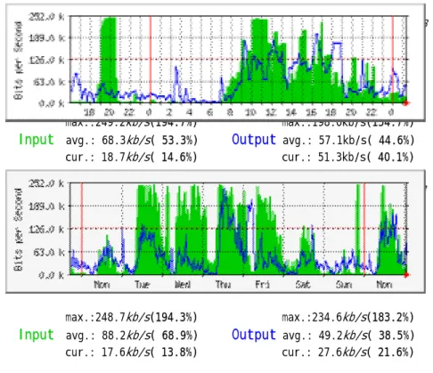
Factors such as types of industry, business operation model, and business scale affect each enterprise that each has its own unique internal structure and computer networking requirement. A common need of an enterprise for its network is to manage its bandwidth utilization effectively. Normally some peak loads or burst traffic concentrate during certain periods. The required bandwidth exceeds that provided by the enterprise network. For the average load, there is sufficient bandwidth to satisfy an enterprise’s demand. This imbalance phenomenon can be demonstrated by Figure 3. Figure 3 shows utilization of a leased line that connects to Internet for a real company. The peak traffic load of the leased line concentrates during office hours from Monday to Friday. The maximum traffic load through the leased line reaches 194% of the subscribed bandwidth. But the average traffic load
through the leased line is smaller than 70% of the subscribed bandwidth. For this company, most of network traffic connected to Internet concentrate on specific office hours. The leased line congestion affect enterprise network performance and operations. Therefore, during office hours, the leased line cannot efficiently support responsive requirements of business operations. However, it shows low network utilization during after hours.
One day traffic statistics (per 5 minutes average) time:5/9/2000 1:28
max.:249.2kb/s(194.7%) max.:198.0kb/s(154.7%)
Input avg.: 68.3kb/s( 53.3%) Output avg.: 57.1kb/s( 44.6%)
cur.: 18.7kb/s( 14.6%) cur.: 51.3kb/s( 40.1%)
A week traffic statistics (per 30 minutes average) time:5/9/2000 1:28
max.:248.7kb/s(194.3%) max.:234.6kb/s(183.2%)
Input avg.: 88.2kb/s( 68.9%) Output avg.: 49.2kb/s( 38.5%)
cur.: 17.6kb/s( 13.8%) cur.: 27.6kb/s( 21.6%)
Figure 3. A leased line traffic statistics of a company
When network congestion occurs, an enterprise should adopt a necessary measure to assure some important or urgent information get through. Two alternatives of resolving network congestion are increase investment and regulate usage.
“Increase Investment” means an enterprise continue to invest enterprise network infrastructure and advanced computer equipments to expand enterprise network system’s bandwidth and capacity. However, if an enterprise use the peak traffic load as its criterion, it would cost the enterprise a lot of money and manpower. The continuing investment would be a heavy financial burden for the enterprise. If an enterprise adopt average traffic load as its upgrade criterion, then enterprise network cannot satisfy the bandwidth requirement in a peak traffic transmission period. Network congestion still exists. The leased line case in Figure 3 has been used to demonstrate this point. If the enterprise enhances its leased line capacity based on the peak traffic load, it should upgrade its leased line bandwidth to 256Kbps. Consequently, the leased line can satisfy this enterprise’s transmission requirement at any time and no congestion exists. But the upgrade expense is expensive.
“Regulate Usage” means that an enterprise does not invest further; instead it assign bandwidth to data flow of urgency or importance. With a proper traffic flow regulation, important and urgent information are quickly transmitted. “Regulate usage” measure allows an enterprise to leverage a
minimum investment and is an economical solution to increase enterprise network efficiency. This strategy is an analogy to a control mechanism of trains’ traffic. For instance, Passenger trains and freight trains would run on a railroad. But at the same time, there is only one train could run on a railroad. The train scheduling mechanism can use the following rules:
1. Passenger trains receive higher priorities than that of freight trains. Passenger trains are further classified in to different priorities.
2. Passenger trains are scheduled mainly during daytimes and office hours. Freight trains are treated otherwise.
With such a train schedule, a railroad administration would efficiently utilize a railroad transportation capacity and satisfy most of requirements of passenger and freight transport. Likewise, an enterprise can apply differentiated service over its enterprise network. A differentiated service mechanism allows network administrators or Internet service providers (ISP) to allocate different network bandwidth to different users according to corporate policy or customers’ agreements. Network administrators may tune the network traffic by factors such as business properties, procedures, users, time urgency, importance of content and interrelationships. With these characteristics of traffic flows, network administrators may assign different transmission priorities to traffic flows. These important traffic flows for an enterprise might generate from the following business information: executive level’s strategy information, orders from important customers, important e-mail, a control information of product manufacture, information of financial operating and internal important information. Such a differentiated service mechanism may let important or urgent traffic flows get better transmission performance and assured timely transmission.
2.2 A classification mechanism of enterprise traffic flow
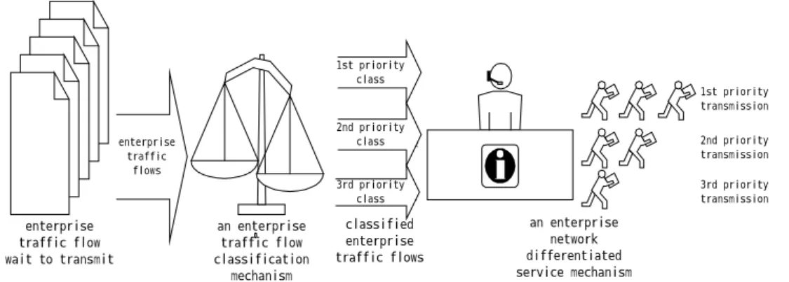
A classification mechanism is used to assign priority to differentiated services. If the classification results correctly represent importance and urgency of enterprise traffic flows, then an enterprise network differentiated service mechanism could really maximize its effective utilization networking resources. Otherwise, bad classification results may result in poor transmission performance. Figure 4 shows a conceptual classification framework of networking.
enterprise traffic flow wait to transmit an enterprise traffic flow classification mechanism 1st priority class 第二優先等級 classified enterprise traffic flows 2nd priority class 第二優先等級 3rd priority class an enterprise network differentiated service mechanism 1st priority transmission 2nd priority transmission 3rd priority transmission enterprise traffic flows
Figure 4. A relationship between an enterprise network differentiated service mechanism and enterprise traffic flow classification mechanism
Differentiated service mechanism would allocate bandwidth leftover from high priority traffic and put them all in the category of best-effort traffic. Therefore, these best-effort traffic flows do not received guaranteed transmission performance.
Each enterprise may have its own the classification criterion. Major factors affecting traffic flow classification mechanism are listed as follows.
1. The managerial rank of sender/receiver:
In an enterprise, the rank of a sender or a receiver is an important index for an enterprise traffic flow classification mechanism. Generally speaking, the information transmitted by executives or high-level managers is more important and urgent than the information transmitted by low-level managers or employees. With efficient business operation information, key executives may make timely quality decisions managers.
2. The business characteristics of each department:
The transmission requirements of each department in an enterprise depend on the business properties each department administered. Usually, marketing and customer service departments face customers directly, and need responsive information received and sent. These departments require more bandwidth and resources. Departments of internal affairs that do not directly face customers may not require real time responses over the intranet. These departments may share the bandwidth leftover by the other departments.
3. Time factor:
Time is another factor might impact the assignment of transmission priority. During office hours of weekdays, marketing departments and customer service departments should receive more network bandwidth and resources to create or maintain more commercial opportunities. During weekends or after hours, marketing departments and customer service departments would no longer face customers. Bandwidth and resources could be transferred to supporting departments such as manufacturing.
4. The features of applications:
Applications are function-oriented. Workflows run across several departments. Applications of various purposes may require different attentions. Executive information system, for example, should receive priority treatment. On the other hand, the normal bulletin board and discussion groups used by employees are applications that do not require guaranteed bandwidth for timely transmission. Routine functions or regular personal communications can be categorized as best-effort traffic flows.
5. Emergency events or other factors:
Emergent events definite have serious impact to business operations. For these emergent events, network managers could allocate assured bandwidth and resources temporarily.
To summarize, good classification scheme should consider factors discussed above. These factors should be reflected in the enterprise network management system. A classification mechanism needs to know the properties of traffic flows to assign appropriate priority. Factors affecting the classification
mechanism include the following: (1) Who is the sender or receiver? (2) The corresponding department that sends it or receives it. (3) The application systems at both sides. (4) Timing.
3. An enterprise network differentiated service mechanism
The DiffServ is a mechanism proposed by IETF Differentiated Service Working Group [13]. According to traffic flows’ transmission properties or SLA (Service Level Agreement), traffic flows can be assigned to different priority classes by routers or switches that support routing functions. The DiffServ mechanism allocates different ratio of bandwidth or resources to different traffic classes. The DiffServ mechanism does not provide end-to-end QoS (Quality of Service) over networks. It only assigns more bandwidth to higher priority traffic flows than that of lower priority traffic flows in the same period. Therefore, higher priority traffic flows would get better transmission performance than lower priority traffic flows and might get away with network congestions.
The DiffServ mechanism uses the “TOS (Type of Service)” field in IPv4 packets [10] or “traffic class” field in IPv6 packets as a basis of traffic flow classification [4]. These two fields are called DS (Differentiated Service) fields or DSCP (Differentiated Service Code Point) [7]. Each DiffServ domain’s border router uses SLA to define a network service requirement of each traffic flow. SLA can be established statically or dynamically. SLA indicates the transmission performance requirements or characteristics of a data flow. Based on SLA, a packet classifier can examine the traffic flow when the packet enters a DiffServ domain. After packets classified, the traffic flow would be metered, marked, shaped, dropped and policed by a traffic conditioner. A classifier works on PHB (Per-Hop Forwarding Behavior)[13] basis. The same PHB traffic flows have the same DiffServ characteristics. There are three types of PHB in the research:
BE (Best Effort Forwarding):
BE is the default forwarding transmission. Most of Internet traffic flows use BE. BE packets are transmitted only when network bandwidth is available. The transmission performance of BE traffic flows would depend on available bandwidth over the network. When the network is not congested, BE traffic flows’ transmission speed is good. Otherwise, its transmission speed is slow. Therefore, BE transmissions do not guarantee the quality of service.
EF (Expedited Forwarding) [8]:
EF is a higher priority transmission than that of BE. A network may reserve some resources and bandwidth for urgent EF traffic flows to transmit data. Other types’ traffic flows could not share the bandwidth reserved for EF traffic flows. EF traffic flows are guaranteed for its transmission performance: An EF packet can run at a rate larger than or equal to the subscribed rate. Therefore, each EF flow receives a better service than that of BEs.
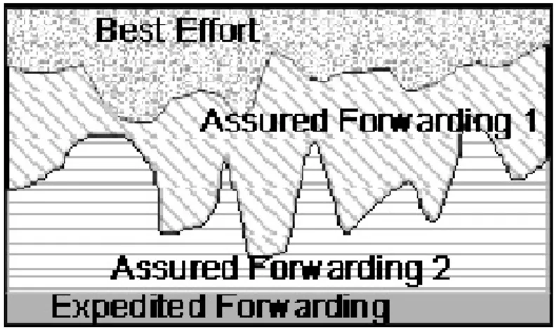
AF assures a minimum bandwidth to each AF flow. AF flows can be further divided into several priority classes. With differentiated network resources and a minimum assigned bandwidth allocation, an AF packet is assured for service quality. A conceptual share of network bandwidth by three PHB’s is shown in Figure 5.
Figure 5. A conceptual shared bandwidth by the three PHB
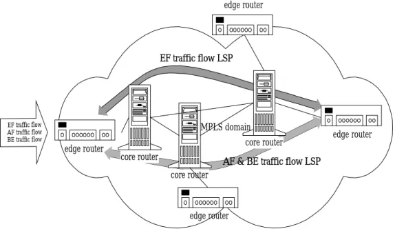
MPLS (MultiProtocol Label Switch) is a routing mechanism that integrates a label swapping and network layer routing. MPLS has been proven to be the main stream of the next generation networking technology and many vendors are providing devices for enterprise solution. This research uses MPLS [3] to an enterprise network using DiffServ mechanism. In a MPLS domain, there are two kinds of routers exist; edge routers and core router. An edge router locates on the border of a MPLS domain whereas a core router resides in the interior of the MPLS domain. Edge routers examine destinations of all traffic flows that are entering the MPLS domain. An edge router uses a LDP (Label Distribution Protocol) [1] provided by MPLS to establish one or more LSPs (Label Switching Path) for these traffic flows. Note that, most LDP allow each core router to use its own local labels to reduce its size of routing table hence accelerate the routing. This is because labels are short and can be reused instead of directly using unique IP addresses. When a traffic flow enters a MPLS domain, the edge router looks up its routing table, assigns the same labels to every packet of same traffic flow according to its destination, and then selects one of LSPs as its routing path. In each LSP, core routers examine each packet’s label, then forward the packet to next hop router or destination according to its label assigned by an edge router. Figure 6 shows the MPLS environment.
The DiffServ mechanism provides differentiated services depending on the content of DSCP field. DSCP field contains 6 bits. These 6 bits in packets would be used by routers to decide which type of PHB would be adopted to transmit packets. Table 1 shows a relationship between DSCP and PHB. MPLS also can use the DSCP field to select a proper LSP.
MPLS domain
core router
core router
core router EF traffic flow LSP
AF & BE traffic flow LSP edge router
EF traffic flow AF traffic flow
BE traffic flow edge router
edge router edge router
Figure 6. A diagram of MPLS supports an enterprise network differentiated service
Table 1. A mapping table of DSCP and PHB [6,7,8]
DSCP PHB Drop Precedence
000000 Best Effort Forwarding
010000 Low 010010 Middle 010100 Assured Forwarding Class 1 High 011000 Low 011010 Middle 011100 Assured Forwarding Class 2 High 100000 Low 100010 Middle 100100 Assured Forwarding Class 3 High 101000 Low 101010 Middle 101100 Assured Forwarding Class 4 High 101110 Expedited Forwarding
MPLS can use a CR-LDP (Constraint-base Routed Label Distribution Protocol)[5] to reserve network bandwidth and select transmission paths for classified traffic flows in advance. In this research, we use MPLS and CR-LDP as tools to differentiate traffic flows in an enterprise network.
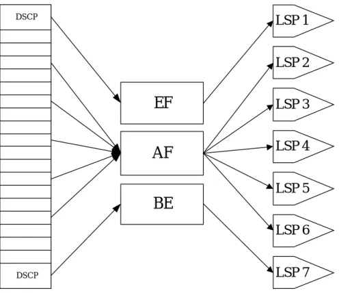
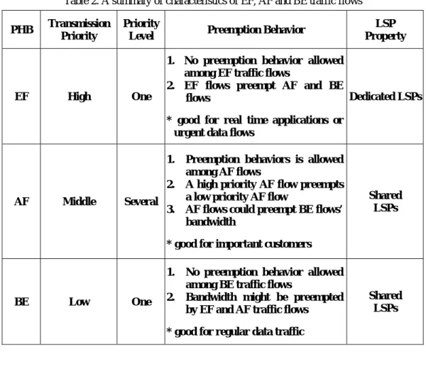
The main reason is that the requirements of DiffServ mechanism can be satisfied by MPLS and CR-LDP. Moreover, MPLS reduces routing cost due to small routing tables. With CR-LDP, each LSP could have different properties, such as: bandwidth limit, duty cycle time and priority, to satisfy different requirements. Figure 7 shows the relationship among DSCP, EF, AF and BE traffic flows and established LSPs. Table 2 is a summary of characteristics of EF, AF and BE traffic flows. It also describes the relationship between MPLS and these three traffic flows.
EF
AF
BE
LSP 1
LSP 2
LSP 3
LSP 4
LSP 5
LSP 6
LSP 7
DSCP DSCPFigure 7. A relationship among DSCP, EF, AF and BE traffic flows and LSPs
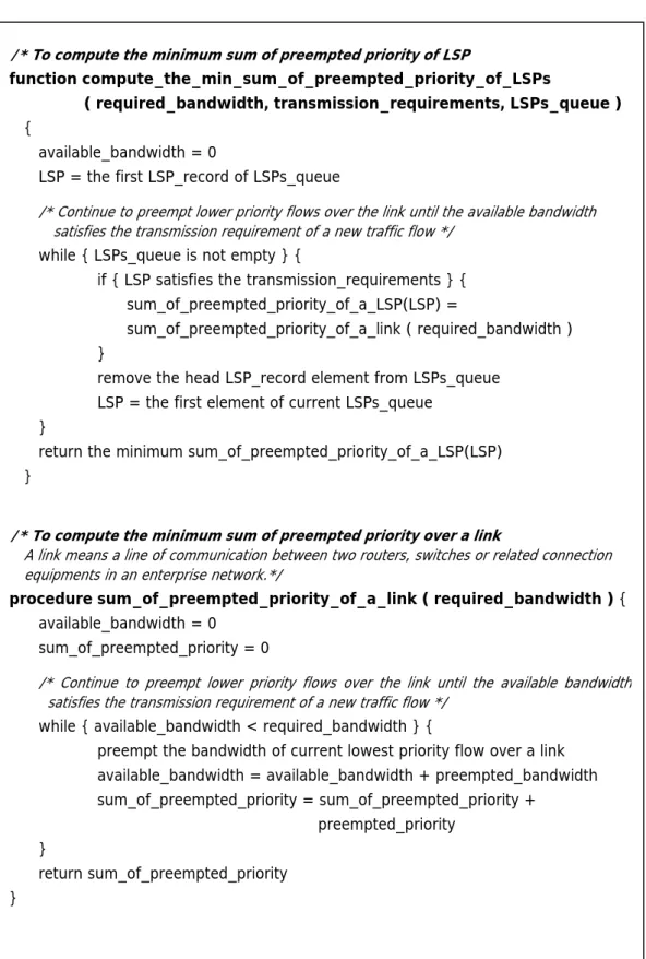
Peyravian and Kshemkalyani proposed a path selection algorithm [10] that uses “minimum hop number” as a key parameter to assure fast transmission. When several transmission paths have the same hop number, the algorithm uses the allocated bandwidth or traffic load of a path as weights. The algorithm selects the path with minimum weights. This algorithm, however, cannot guarantee transmission service quality for a traffic flow. In this research, different weighting parameters, such as: a transmission duty cycle time and bandwidth utilization of a transmission path are used to assure transmission quality of service. With these parameters, our algorithm first selects the available transmission path, and then the Minimum Priority algorithm we proposed in this paper would select the best paths described in Figure 8. Therefore, high priority traffic flows obtain better transmission performance and better service qualities than otherwise.
Table 2. A summary of characteristics of EF, AF and BE traffic flows
PHB Transmission Priority
Priority
Level Preemption Behavior
LSP Property
EF High One
1. No preemption behavior allowed among EF traffic flows
2. EF flows preempt AF and BE flows
* good for real time applications or urgent data flows
Dedicated LSPs
AF Middle Several
1. Preemption behaviors is allowed among AF flows
2. A high priority AF flow preempts a low priority AF flow
3. AF flows could preempt BE flows’ bandwidth
* good for important customers
Shared LSPs
BE Low One
1. No preemption behavior allowed among BE traffic flows
2. Bandwidth might be preempted by EF and AF traffic flows
* good for regular data traffic
Shared LSPs
/* Minimum Priority algorithm *
Minimum_Priority_Algorithm {foreach flow enters the domain {
LSP_queue(flow_id) = establish_available_LSPs_queue ( ingress, egress ) min_preempted_priority_LSP = compute_the_min_preempted_priority_of_LSPs
( required_bandwidth,transmission_requirements , LSPs_queue( flow_id ) )
} }
/* To search all available LSPs that satisfy the transmission requirements of a traffic flow from an ingress router to an egress router */
function establish_available_LSPs_queue ( ingress, egress ) {
foreach { LSPs exist from ingress to egress } {
if { this LSP satisfies the transmission requirements } { insert LSP_record into LSPs_queue
} }
return LSPs_queue }
/* To compute the minimum sum of preempted priority o LSP f
function compute_the_min_sum_of_preempted_priority_of_LSPs
( required_bandwidth, transmission_requirements, LSPs_queue )
{
available_bandwidth = 0
LSP = the first LSP_record of LSPs_queue
/* Continue to preempt lower priority flows over the link until the available bandwidth satisfies the transmission requirement of a new traffic flow */
while { LSPs_queue is not empty } {
if { LSP satisfies the transmission_requirements } { sum_of_preempted_priority_of_a_LSP(LSP) =
sum_of_preempted_priority_of_a_link ( required_bandwidth ) }
remove the head LSP_record element from LSPs_queue LSP = the first element of current LSPs_queue
}
return the minimum sum_of_preempted_priority_of_a_LSP(LSP) }
/* To compute the minimum sum of preempted priority over a link
A link means a line of communication between two routers, switches or related connection equipments in an enterprise network.*/
procedure sum_of_preempted_priority_of_a_link ( required_bandwidth ) {
available_bandwidth = 0 sum_of_preempted_priority = 0
/* Continue to preempt lower priority flows over the link until the available bandwidth satisfies the transmission requirement of a new traffic flow */
while { available_bandwidth < required_bandwidth } {
preempt the bandwidth of current lowest priority flow over a link available_bandwidth = available_bandwidth + preempted_bandwidth sum_of_preempted_priority = sum_of_preempted_priority +
preempted_priority }
return sum_of_preempted_priority }
Figure 8 Minimum Priority algorithm
When establishing a new LSP for a flow entering the MPLS domain, for each congested single link, the algorithm will preempt the lowest priority flow. The preempted flow will find an alternative new link or path, by preemption if needed, to continue its transmission. In other words, the preemption has domain effect until the whole network converges to a stable transmission.
4. A simulation analysis
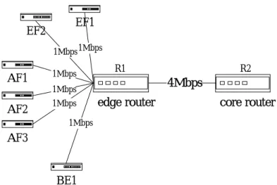
The Network Simulator - ns (version 2 beta release 5) [14] is used for verifying transmission behavior of differentiated services. The ns-2 is implemented on a PC with a pentium-III-500 CPU, 256MBytes RAM running Linux operating system. A simplified enterprise network architecture and two scenarios are simulated. The first scenario’s is an enterprise network with differentiated service mechanism operating in a single LSP. The second scenario is a network operating in multiple LSPs.
1. Differentiated services in a single LSP
Figure 9 is the simplified network topology for simulating three PHB differentiated service in a single LSP. EF1 EF2 AF1 AF2 AF3 BE1
edge router core router
4Mbps 1Mbps 1Mbps 1Mbps 1Mbps 1Mbps1Mbps R1 R2
Figure 9. A differentiated service mechanism in simplified enterprise network topology Figure 9 shows that EF1 and EF2 are classified as EF traffic flows. AF1, AF2 and AF3 are classified as AF traffic flows and BE1 is a BE traffic flow. These six traffic flows have different transmission properties and priorities over the enterprise network. The required bandwidth of each traffic flows is 1 Mbps. These traffic flows would enter the enterprise network from an edge router R1, and then pass through the R1-R2 link. Therefore, the edge router R1 faces 6 Mbps bandwidth. But, the available capacity of R1-R2 link is 4Mbps, and cannot fully satisfy 6Mbps traffic flows. Congestion will occur over the R1-R2 link. Because CBQ (Class Base Queueing) is a mature and proven technique for supporting multiple queues over l single link, a CBQ differentiated service mechanism over the R1-R2 link is used. The starting transmission time of the six traffic flows are specified in Table 3.
Table 3. Start transmission time of the six traffic flows
Start transmission time 1st second 2nd second 3rd second
Traffic flows EF1, AF1, AF2, BE1 EF2 AF3
Figure 10 shows bandwidth allocations of the LSP (R1-R2 link) by the network administrator. The EF1 receives 30% shares of the LSP. That is, EF1 receives 1.2 Mbps bandwidth from the
R1-R2 link (4Mbps * 30%). Other traffic flows also receive different shares of bandwidth from the R1-R2 link. Note that the proportion of bandwidth assigned to BE1 traffic flow is 0%, i.e. no bandwidth available to BE. Due to the lowest transmission priority of BE traffic flow, BE traffic flow could not receive any bandwidth from the R1-R2 link wherever there is any other flow of a higher priority competing for the bandwidth.
AF-LSP 20% BE-LSP 0% AF-LSP 10% AF-LSP 30% EF-LSP 10% EF-LSP 30%
Total
Bandwidth
Flow EF1 Flow EF2 Flow AF1 Flow AF2 Flow AF3 Flow BE1
Figure 10. A diagram of bandwidth allocation in a LSP
In this scenario, the DiffServ mechanism is implemented as follows. EF flows receive the guaranteed bandwidth at any time. EF flows are scheduled in FIFO. AF flows receive assured bandwidth after EF flows have been satisfied. AF flows are scheduled according to their transmission priorities. BE flows are allowed to transmit only when bandwidth for EF and AF flows are assigned.
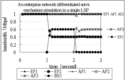
An enterprise network differentiated servic mechanism simulation in a single LSP
EF2 EF1 AF1 AF2
AF3
0
0.2
0.4
0.6
0.8
1
0
1
2
3
time(second) bandwidth (Mbps )EF1 EF2 AF1 AF2
AF3 BE1
Figure 11. Simulation results of differentiated service in a single LSP Figure 11 shows simulation results and several observations are summarized as follows.
(1) At time t = 0, the EF1, AF1, AF2 and BE1 flows begin to transmit over the R1-R2 link. Depending on the simulation scenario, EF1 and AF1 flows receive 1.2 (4 (total bandwidth) * 0.3, see Figure 10) Mbps bandwidth though either one of them needs only 1 Mbps. Therefore, each of
these four flows receives the needed 1 Mbps bandwidth. No congestion occurs over the R1-R2 link from time t = 0 to time t = 1.
(2) At time t = 1, the EF2 flow begins its transmission and congestion occurs over the R1-R2 link. According to the simulation scenario, the EF2 flow receives 0.4 (4 * 0.1) Mbps guaranteed bandwidth. After satisfying the transmission requirements of EF and AF flows, there is only 0.8 Mbps (4 (total bandwidth) – 1.0 (for EF1) – 0.4 (for EF2) – 1.0 (for AF1) – 0.8 (for AF2) ) bandwidth available. Since the AF2 flow has higher priority than the BE1 flow, the AF2 flow would receive the extra 0.2 (1.0 – 0.8) Mbps bandwidth that is not the assured bandwidth for the AF2 flow. That is, AF2 takes away 0.2 Mbps from BE1. There are only 0.6 (0.8 – 0.2) Mbps available for BE1 flow. Figure 11 shows BE1 drops to 0.6 Mbps at t = 1.
(3) At time t = 2, the AF3 flow begins its transmission and deteriorates the congestion over the R1-R2 link. The AF3 flow receives 0.4 (4 * 0.1) Mbps assured bandwidth. After all guaranteed and assured bandwidth allocated to EF and AF flows, only 0.4 ( 4 (total bandwidth) – 1.0 (for EF1) – 0.4 (for EF2) – 1.0 (for AF1) – 0.8 (for AF2) – 0.4 (for AF3) ) Mbps bandwidth are available for remaining AF and BE flows. Comparing the priorities of AF2, AF3 and BE1 flows, the AF2 priority is the highest and it first gets the 0.2 (1.0 – 0.8) Mbps extra bandwidth, preempts from BE1, that is not the assured bandwidth for the AF2 flow. The AF3 is of the second highest priority; it also gets the available 0.2 (0.4 – 0.2) Mbps extra bandwidth, preempts from BE1, that is not the assured bandwidth for the AF3 flow. Now the AF3 flow uses 0.6 Mbps bandwidth. Since the BE1 flow is of the lowest priority, it receives no bandwidth after time t = 2.
In summary, when a new flow begins its transmission over the R1-R2 link and there is no bandwidth available, the bandwidth reallocations of flows depend on their priority. The EF flows get their required bandwidth. Thereafter, AF flows also get the assured bandwidth. The BE flow receive its bandwidth only when EF and AF flows are satisfied.
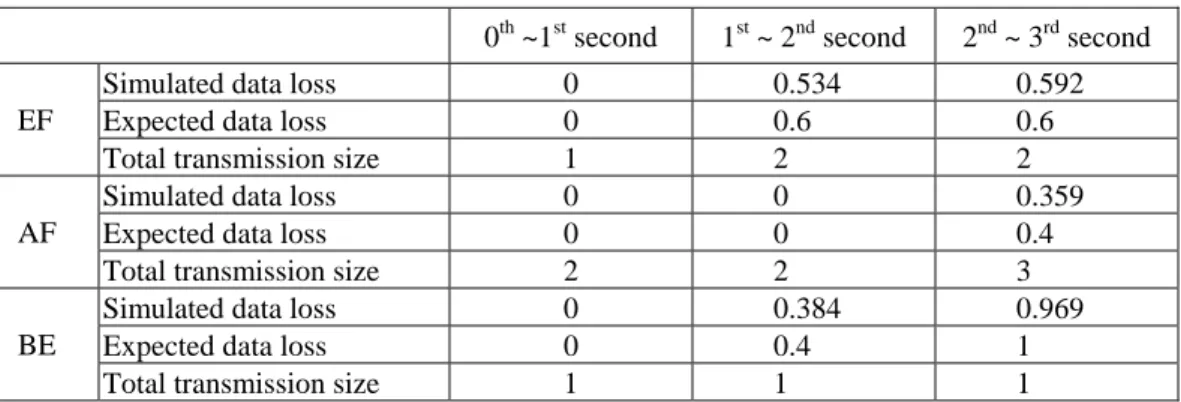
Table 4 is a comparison of the EF, AF and BE flows’ expected transmission loss and simulation results. It shows that the simulation results approximate the expected transmission loss. This result demonstrates the feasibility and correctness of the enterprise network differentiated service mechanism.
Table 4. A comparison of traffic flows’ expected transmission loss and simulation results in a single link
(unit: Mbits)
0th ~1st second 1st ~ 2nd second 2nd ~ 3rd second
Simulated data loss 0 0.534 0.592
Expected data loss 0 0.6 0.6
EF
Total transmission size 1 2 2
Simulated data loss 0 0 0.359
Expected data loss 0 0 0.4
AF
Total transmission size 2 2 3
Simulated data loss 0 0.384 0.969
Expected data loss 0 0.4 1
BE
2. Differentiated services in Multiple LSPs
Three PHB traffic flows of differentiated services are simulated in a mesh network topology shown in Figure 12. This is used to simulate a multiple LSPs in an enterprise network. R1 in Figure 12 is the edge router of the enterprise network whereas R2, R3 and R4 are core routers. Three LSPs are available to support differentiated services in the enterprise network. Table 5 describes the simulation parameters: type of traffic flows, the start time of flows, the guaranteed bandwidth of flows, and the delay time limit of flows. Delay time here means the maximum tolerance of the data flow that is delayed. EF1 EF2 AF1 AF2 AF3
BE1 Router R1 Router R2
1Mbps 20ms 1Mbps 1Mbps 1Mbps 1Mbps 1Mbps 1Mbps Router R4 Router R3 2Mbps 10ms 1Mbps 5ms 2Mbps 10ms 1Mbps 5ms
Figure 12. An enterprise network differentiated service mechanism in a multiple LSPs topology
Table 5. Simulation parameters of an enterprise network differentiated service mechanism in a multiple LSPs
Traffic flow Start time
(Second)Bandwidth
(Mbps)Delay time
(ms)EF1 0
1.0 15
EF2 2
0.4 20
AF1 0
1.2 None
AF2 1
0.8 None
AF3 3
0.4 None
BE1 0 0.0 NoneWith the network topology of Figure 12 and the simulation parameters of Table 5, simulation results are shown in Figure 13.
R1-R4-R2 LSP Transmission 0 0.2 0.4 0.6 0.8 1 0 1 2 3 4 Time(Second) Badwidth (Mbps) EF1 R1-R3-R2 LSP Transmissions 0 0.2 0.4 0.6 0.8 1 0 1 2 3 4 Time(Second) Bandwidth (Mbps ) AF1 AF2
Figure 13.A Figure 13.B
R1-R2 LSP Transmissions 0 0.2 0.4 0.6 0.8 1 0 1 2 3 4 Time(Second) Bandwidth (Mbps )
EF2 AF3 BE1
Figure 13.C
Figure 13. Simulation results of differentiated services in multiple LSPs
Several observations are in order.
(1) At time t = 0, the R1-R4-R2 LSP has the minimum transmission delay of 10 ms and is the only choice for the EF1 flow to guarantee its 15 ms delay requirement.
(2) At time t = 0, the AF1 only requires 1 Mbps bandwidth. Because of the assured bandwidth of 1.2 Mbps, only the R1-R3-R2 LSP could satisfy. The path of R1-R2 is not chosen because it cannot assure the 1.2Mbps bandwidth that AF1 requires (see Table 5).
(3) At time = 0, having assigned EF1 and AF1, the network can only assign R1-R2 LSP to BE1 since that is the only LSP left. Technically, LSP R1-R3-R2 still has 1 Mbps but the assured bandwidth of AF1 is 1.2 Mbps with 0.8 Mbps left to others. This 0.8 Mbps cannot satisfy 1 Mbps of BE1. (4) At time t = 1, the AF2 flow begins its transmission. Only the R1-R3-R2 LSP has 1 Mbps idle
bandwidth. Therefore, AF2 takes this remaining bandwidth.
(5) At time = 2, all LSPs are allocated to the EF1, AF1, AF2 and BE1 flows. No idle bandwidth is available. Bandwidth preemption would occur to satisfy the transmission requirement of EF2 flow. According to Minimum Priority algorithm, the EF2 flow selects the R1-R2 LSP as its transmission path. EF2 now takes away some bandwidth from BE1. Since the network
administrator only guarantees 0.4 Mbps to EF2 (see Table 5), EF2 must preempt 0.4 Mbps from BE1 where BE1 is now the lowest priority in all flows. Note that BE1 keeps using the remaining 0.6 Mbps bandwidth.
If the EF2 flow selects the R1-R3-R2 LSP as its transmission path, it will cause that the AF2 flow must reselect the R1-R2 LSP and preempt the 0.8 Mbps bandwidth from BE1 flow. This LSP selection of EF2 would reduce the network utilization, the 0.6 Mbps bandwidth are idle in the R1-R3-R2 LSP, and increases the transmission path overhead of AF2.
(6) At time t = 3, the AF3 traffic flow begins its transmission. By using Minimum Priority algorithm, AF3 now can only preempt BE1 since BE1 is now the lowest priority flow. The preempted bandwidth is 0.6 Mbps and is exactly the amount needed to assure AF3.
Table 6 A comparison of traffic flows’ expected transmission loss and simulation results in multiple LSPs (unit: Mbits) 0th ~ 1st second 1st ~ 2nd second 2nd ~ 3rd second 3rd ~ 4th second
Simulated data loss 0 0 0.598 0.594
Expected data loss 0 0 0.6 0.6
EF
Total transmission size 1 1 2 2
Simulated data loss 0 0 0 0.366
Expected data loss 0 0 0 0.4
AF
Total transmission size 1 2 2 3
Simulated data loss 0 0 0.964 1
Expected data loss 0 0 1 1
BE
Total transmission size 1 1 1 1
Table 6 lists a comparison of EF, AF and BE traffic flows’ expected transmission loss and the simulated data losses. It shows the simulated data losses of EF, AF and BE traffic flows are close to the expected transmission losses. This also demonstrates MPLS could support an enterprise network that uses differentiated service mechanism.
5. Conclusion
With advances of Internet applications, enterprises gradually adopt information technologies to enhance their business performance. The prevailing of E-commerce also rests much business burden on a responsive intranet. To survive or to compete in today’s competitive business environment, executive managers must make timely business decision. A responsive decision calls for a responsive network.
The enterprise network differentiated service mechanism may solve an insufficient bandwidth issue over an enterprise network. Differentiated service mechanisms depend on the transmission